What is an Induction Heater?
What is an induction heater? Exactly what it says, it uses an induction to heat.
In basic terms its a coil of wire that has a sinusoidal current flowing through it, a piece of metal is placed into this coil and the current is transferred, the current heats up the metal. You may have seen it before on TV where someone cracks an egg onto half of a frying pan, the egg cooks on the pan but not the hob. A coil of wire is beneath the frying pan, a high frequency current transfers into the metal pan causing it to heat up. I always found this a fascinating subject and always wanted to build one from the age of 12 but didn't have a clue, eventually at the age of 17 I came across the subject on the internet and decided that I would build one.
I would say that this was the most frustrating project and cost me a lot of time and money. The first heater that I made was quite simple and worked quite effectively but required me to manually tune it (as I will explain later in the theory). I thought that I would go bigger and better because I wanted to heat and forge metal, so I spent lots of time and money building a 5kW unit. I had written a 50 page project log and my hard drive failed on my computer at the same time that my memory stick failed, I lost everything and lost interest in the subject. The date is 11/08/2012 and I have decided that I will start it again since I'm earning a decent wage, it will also tie in with other projects that I'm doing. Whoever reads this page may find it a little easier to understand if they have a basic understanding of electronic components and theory, especially RLC and inverter circuits.
The theory of an induction heater is relatively simple and works on the principle of resonance, its construction is almost the same as a solid state tesla coil. A quick explanation of construction/theory;
A voltage source is required, usually the mains voltage is used which needs to be converted to a direct current by the aid of a bridge rectifier. This DC source contains ripples which are solved by the use of large electrolytic filter capacitors. This DC voltage is then turned back into a high frequency alternating current by the use of an inverter. This alternating current is sent to what is known as a matching transformer/inductor which limits the amount of current that can be drawn from the inverter. The alternating current is then sent to a tank circuit which is made up of a capacitor and an inductor, the inductor is known as the work coil (where stuff is heated). When the alternating current is at a certain frequency it causes resonance to occur between the inductor and capacitor causing a large increase in current or voltage. When something is placed into the work coil a current is induced into it, the current is high enough to heat the metal. If there was no resonance in the circuit then the current would remain low and therefore heating would be greatly reduced.
It uses two methods of operation:
Series Resonant
The series resonant consists of a capacitor, inductor and resistor all in series as shown in the diagram on the right. When in resonance the current in the tank remains the same as that coming from the inverter but the voltage rises, in theory the voltage is limited by the resistor.
Parallel Resonant
The parallel resonant consists of the capacitor in parallel with the inductor, the resistor being in series with them as shown in the diagram on the right. When in resonance the voltage in the tank remains the same as that from the inverter but the current rises, limited by the resistor.
Explain differences
AC inverter explanation
The inverter is the most difficult part of the whole project, it is the part that has given me the most grief in the past. The inverter firstly converts the AC supply to DC, the DC is then smoothed out with high capacity electrolytic filter capacitors. The smooth DC is sent to a H-bridge which converts the DC to high frequency AC, the H-bridge consists of four transistor that alternate the flow of the output therefore creating AC. The circuit will use a bridge rectifier to convert the mains supply AC to DC which then charges the filter capacitors, if the power was to be turned on at full then there would be a huge surge in current, the filter capacitors need to be charged by limiting the current to them, ie a resistor. DC from 230V mains will be 325V, this means that the drivers for the H-bridge cannot share the same ground. There are two options; use pulse gate drive transformers or separate isolated power supplies. I have used gate driver transformers in the past, but it does not always switch the transistors at their full abilities. Instead a transformer with four secondaries can be used to provide four separate power supplies to the drivers, which allows a gate driving chip to be connected straight to the transistor, an optical isolator provides a signal to the driver from the controlling circuit.
The inverter has a control circuit which in basic provides the drivers with a specific frequency, it can also include other extra abilities including transistor protection. A lot of drivers have something called desaturation protection, when a transistor has a current flow higher than its rating such as from a short circuit it causes a voltage drop between the drain and source (I'm relating to an IGBT, Insulated gate bipolar transistor). A circuit detects this voltage drop and pulls the drivers output to zero volts. Another method of over-current protection is to use a shunt between the H-bridge low side and ground, a voltage drop across this is dependant on the current, it works on similar principle as the desaturation protection by disabling the drivers when too much current is present.
under construction
The induction heater that I had previously built was the parallel resonant configuration, it ran at 150W with great success. The MOSFET's that I used lasted and didn't overheat, until I tested this circuit on a tv flyback transformer which blew the transistor within 30minutes, it created some pretty decent arcs. The oscillator that I used was the 4046 chips which contains a voltage controlled oscillator (VCO) and an exclusive OR gate (XOR). It produces a perfect square wave, has a frequency range that can be altered and has some additional features which will be mentioned at a later time.
August 11/08/2012
I started writing this page. In the past I enquired about some induction heating capacitors, I could not afford them previously, today I asked for a requote.
November 07/11/2012
I have been occupied with other projects so it has been a very long time since a wrote anything on this page. About two years ago I enquired about some induction heating capacitors, regular capacitors won't work due to two reasons; current rating and ESR. Current ratings are usually a maximum of 10amps, which means that multiple capacitors would need to be used resulting in an expensive and rather bulky capacitor bank. ESR stands for equivalent series resistance, basically its electrical losses in the capacitor which are greater at higher frequencies. A high ESR means a lot of power is wasted, it is much better to use a capacitor that has been designed specifically for inductive heating. At the time when I enquired about one of these capacitors I didn't have enough money, and that was at half the retail price, so I put the project on hold. About 3 months ago I enquired about the capacitor again to see if the offer still stood, it did, but unfortunately they wouldn't accept paypal. About 3 days ago I got confirmation that they now accept paypal, so I sent the payment of about £120. Not quite sure how long the postage is going to take but the components coming from Jerusalem, Israel.
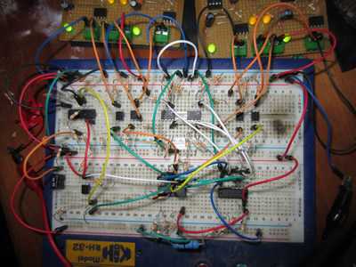
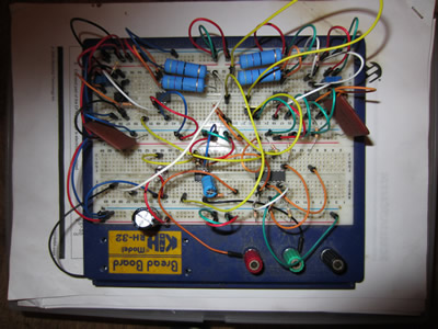 A couple of weeks ago I started designing some to the circuitry, I usually draw a schematic of what I'm going to prototype but this time I just built it straight onto a breadbaord, making it up as I went along. The circuit that I built was to drive the H-bridge, a H-bridge is an arrangement of four transistors that when switch in a specific sequence can be used to create an alternating current. The transistors that I'm using are the brick style IGBT's, these are a module that bolts straight onto a heatsink, they require a circuit to drive them. A driver chip specifically designed for IGBT's was used just to make things easier, the one that I used is capable of 9A peak currents. Large carbon composite resistors were used to limit the current to a sensible level, maintaining relatively fast turn-on speeds.
When switching the transistors in a H-bridge only two can be on at one time, factors such as transistor turn-on/off time can cause problems. If the next set of transistors were to switch on before the last pair switch off then it will cause the power supply to short, which is not good when you've got a bank of charged filter capacitors across the supply. There needs to be a propagation delay, the switch-off delay on these IGBT's is 800ns, so I will use a delay of 1us. I used a 4000series logic chip to provide a clean 15V output (it's also used to invert the voltage for the other half of the driver circuit), this connected to a capacitor and a comparator can be used to create a delay. To create a longer delay the reference voltage on the comparator is increased, which increases the voltage required on the capacitor and therefore causes the logic to change at a later time. An overview of this circuit is that it receives a square wave voltage from an oscillator, it is sent through a logic chip and charges a capacitor, a comparator reads the voltage off the capacitor and when at a certain level switches logic, this goes to an optoisolator chip (this is to isolate the driver circuit from the high side 320Vdc), the isolator switches the igbt driver which in turn drives the IGBT.
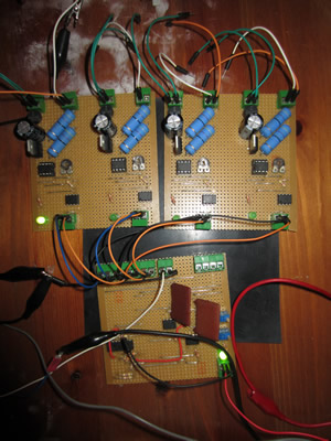
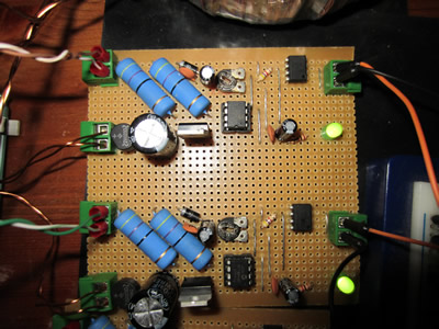
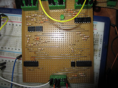
I built the circuit straight onto a piece of circuit board, the top two boards are to drive the IGBT's, the bottom board is the propagation delay board. I have included a couple of extra features, one of them being that the IGBT driver boards have their own separate voltage regulators. The two high-side IGBT's on the H-bridge will require an 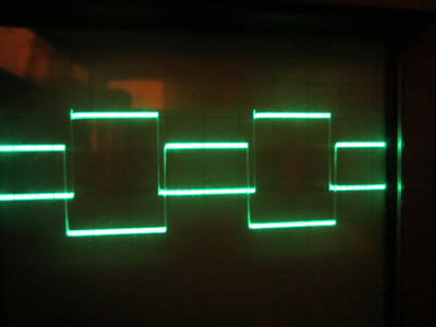 isolated power supply, I wound a transformer quite a while ago with four secondaries, one for each IGBT driver.
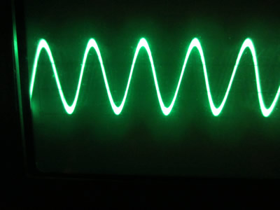
This oscilloscope trace shows two outputs, one for each pair of IGBT's. As you can see there is a delay between the turn off and turn on of the other, this has been tuned to a delay of 1us.
Today I brought a large heatsink into work and drilled out some mounting holes for the IGBT's. Holes were also drilled for some power resistors which will be used to charge the filter capacitors, and holes for two bridge rectifiers.
November 10/11/2012
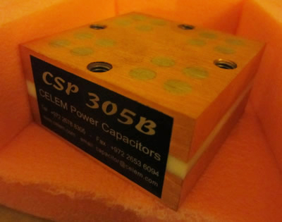
A couple of days ago I received the capacitor, unfortunately there was an additional charge of £39.84 because of a custom tax, afterall it did come from Israel, four days delivery is certainly faster than I had expected. It is rated 5uF, 400Vrms, 800Arms at 300kVAr. It can handle a large amount of power for such a small capacitor, 60 x 60 x 30.2mm. The losses in the capacitor are 5 x10^-4 of reactive power, this means that if the capacitor is running at its maximum rating then there will be a total of 150W of heat, it won't be running on the limit.
Today I tried out the driver circuit on my IGBT bricks, somehow the low side on one of the IGBT's has blown. I can't understand why because all of the others are fine and usually when one blows it shorts the emitter and collector, this hasn't happened. The IGBT remains off but the gate draws 1.3A of current, the circuit has no problems driving smaller single IGBT's, I'm just wondering if these are faulty.
Instead I'm going to buy some smaller regular IGBT's, they have same voltage and current ratings, but are a lot faster and more compact. The only reason for using bricks is becuase they are modular, can be easily replaced and the mounting bracket is isolated.
November 11/11/2012
I have ordered a load of components which should be sufficient to get the heater working at its maximum ratings. I think the problem was with the driver circuit. An optical isolator is used which requires a voltage of 5V in order to work, to regulate the voltage I used a preset potentiometer from a 15V regulated source. I think that the problem lied with the voltage regulators, they work at a very high switching frequency, a capacitor is supposed to be used on the output to remove noise, I didn't have any matching ones so never used them. I think that this may have created some noise on the gate of the IGBT, causing it to blow, although I find this very hard to believe. I have bought quite an array of components costing me about £70, the main components are the IGBT's, these are rated at for 1200V at 40A (operating 25degC). The IGBT has similar turn on/off times and are designed specially for inductive heating, I got them for £3.38 each which is not bad. I have chosen a voltage rating of 1200V just incase of any voltage spikes, it will only be running at 320Vdc. I have also bought some 20V zener diodes that will be paired between the IGBT gate and ground, this will prevent over-voltage to the gate, this should not happen as the gate drive resistors are carbon composite (to reduce inductance and prevent inductive kick), just a precaution.
I have been doing a lot of thinking on the brains of this heater, it will be controlled via a microcontroller instead of logic chips. I have created a board specially to create an inverted output and a propagation delay, this will no longer be required as I can incorporate it into the microcontroller. I will have full range of the output power because it can be pulse width modulated and I can use it to drive a serial LCD which can display power output, frequency, power factor, etc... A resistor is going to be placed between the emitter and ground to measure the current flowing, a value of 0.1ohm has been chosen, this means that for every amp that goes through it will create a voltage drop of 0.1V across the resistor. The DC voltage will be 320V and the power rating 2.2kW meaning that a current of 6.88A should be the maximum, if the current goes higher than this then the microcontroller will turn off the IGBT "chopping" the current. I have been thinking of what would happen if the power supply was to be cut when in operation, quite simply the microcontroller would discharge the filter capacitors and drive the IGBT's low. A large capacitor will be used in the control circuit to keep power on allowing the IGBT's to remain low until the filter capacitors have discharged, I may have to increase the capacitance of the capacitors on the driver boards.
November 14/11/2012
 The components have been received today, unfortunately I only get about 2 - 3 hours after work to get anything done. The first priority was to improve the driver circuits by smoothing some of the signals. I have placed a small electrolytic and ceramic capacitor after the voltage regulator to remove all of the noise, I have also placed some on the supply of the optoisolator to further reduce noise cause by the input signal. A 20V zener diode has been placed between the output and ground, this is to prevent over-voltage damage on the IGBT gate, although extremely unlikely.
I also built a circuit on the breadboard to run the driver circuits, basically it has two outputs, one for each transistor pair. I microcontroller drives a small pair of MOSFET's which in turn driver the optoisolators on the drive boards. For some strange reason the microcontroller has not been functioning properly and seems to be really slow even though I have overclocked it from its standard 4MHz to 32MHz. Switching the outputs from low to high/ high to low has a long delay, I will do some reading tomorrow to see if there's an alternative command that operates faster.
April 27/04/2013
Its about time this project was started again. I remember looking into a different method other than using PIC chip to control the circuit, it would involve me having to learn a different programming language which I simply don't have the time to do at the moment. I'm going back to good old CMOS logic, it makes things pretty easy and robust. There will be another circuit that reads the outputs of the IGBT drivers, it will only allow two IGBT's on, this is to prevent short circuits from occurring. A comparator will also be connected to the enable part of this circuit which is from a shunt connected across the negative to the IGBT's, it will limit the current that flows. Quite simply I will limit the current instead of the duty cycle to vary the amount of power.
May 04/05/2013
I'm getting closer to completion, the driver circuits are almost complete and soon shall be starting the power circuit.
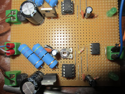
The problem I was having with my circuit was allowing one side of the H-bridge to turn off before the other, my problem was that I was using a delay circuit. The best way I thought of was to use feedback from the drivers. If one OR the other high/ low side driver is on then it uses logic gates to not allow the other half of the bridge to turn on, therefore preventing any shorting from occurring. The first picture of the left shows the original driver circuit, the middle picture shows the addition of some optical isolators and a 5V voltage regulator to replace the preset potentiometers. The right picture shows the logic circuit. When power is applied to the driver circuits they automatically turn on, so I added some MOSFET's to pull the inputs up to positive and therefore the drivers to zero volts. Due to me adding an LED to the output of the optical isolator it pulls the pin down to 2V which is just below the threshold voltage for logic chips, so I had to add a comparator, enlarging the circuit slightly. I tested out the circuit using the output from a VCO (voltage controller oscillator) and it worked absolutely perfect, I must now assemble the whole thing onto a circuit board.
I did a little test hooking this up to the original tank circuit, running it at about 40V at 5A. There was a huge amount of noise in the tank, I had the suspicion that it was the capacitors. So I replaced the old capacitor with my purpose built one, the resonance was perfect, no noise at all. I must make a cooling system for this because I'm not willing to blow my capacitor. I also bought a shunt to measure the current through the H-bridge, this will be used for two purposes; one is to shut down the whole thing incase of a huge over current, the other is to give feedback to a regulator.
May 06/05/2013
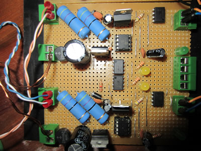
 I converted my prototype from breadboard onto a circuit board, I never make a design and just plan it in my head. I tested the board and made just one mistake, I had not cleaned the tracks thoroughly enough and there was a little bit of metal causing one to short. Once I cleaned this little bit off the board worked perfectly. There is only two input pins, one is an enable and the other a clock from the oscillator.
I originally wanted to construct an induction heater just to have a play about, then I wanted it for a forge but realised that the power wouldn't be quite high enough from a plug socket. I have decided that I will use it to create sodium from salt. Induction heaters are used for melting things in a confined atmosphere, whether it be a vacuum or a special gas. When making Sodium it requires the electrolysis of Sodium Chloride (Salt, NaCl) which also produces chlorine gas, using the induction heater I can keep a constant temperature and keep the setup clean which may not be possible using a burner. I have a couple of uses for the sodium but unfortunately no use for the chlorine gas, which is very dangerous. When chlorine gas touches water it turns to hydrochloric acid, this is why breathing too much in will be lethal.
May 11/05/2013
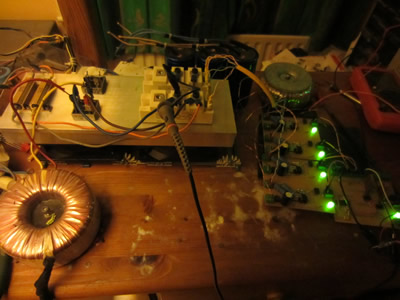
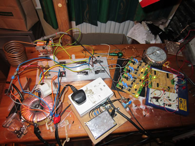
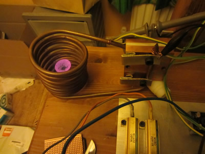
I have finally got the heater working, running at about 50V at 5A. My setup is a little messy at the moment because I'm just prototyping stuff as I go along, when the whole thing is complete it shall be placed in a perspex unit. The bottom left shows my setup, the torroidal transformer and the plug socket on the left is the supply to the bridge, I have a voltage regulator that varies the voltage to the plug and therefore varies the voltage out of the transformer. The tank circuit has been quickly put together using some make-shift clamps, I will probably run this at no more than 400W without adequate cooling for the coil and capacitor. The middle picture shows me heating a two pence coin to curie temperature, the point at which the steel loses its magnetic properties, heating beyond this relies on much higher powers. To the right shows the coil at resonance showing a peak voltage of 75V, 53Vrms. There is one problem with the following circuit, I have not used anything to limit the current to the tank. I should have used something like an impedance matching inductor or transformer. Instead I let it draw the limit from the supply transformer, It got a bit warm. The main problem is that it dumped all the power from the filter capacitors through the bridge, it would almost certainly blow the transistors if these capacitors were any larger.
The next step is to install the current limiting circuit to protect the transistor incase of a short or if the oscillator stops which will lead to a short. Instead of doing this I decided to make an impedance matching transformer and hook the whole system straight to the mains supply, as soon as I plugged it in the supply tripped without even switching the plug on. I have recently had RCD's installed in the house, so I know that it is an earth problem, although I was puzzled why. After a bit of thinking I realised that it was due to the oscilloscope. Now the mains supply goes to a bridge rectifier, the negative end is earthed to the oscilloscope which is also earthed to the supply. Now an RCD reads earth leakage current, in this case its leaking down the neutral, through the bridge rectifier and then to the oscilloscope causing the RCD to trip.
I have a couple of problems now, I could quite easily sort this out by isolating it by a transformer, but an isolation transformer rated at 2KvA would be very expensive and bulky. I needed the oscilloscope to measure the current to setup the current limiting circuit, so to do this I will have to do it on the lower voltage from a transformer. As for the tank circuit it doesn't really matter because I'm toying with the idea of using a transformer to couple the tank to the bridge. The voltage my capacitor can run at is 400Vrms, using the voltage from the inverter it will make 230Vrms. If I use a turns ratio of 1 to 1.5 then the output voltage will be 345Vrms, I would rather make use of its full ratings.
May 18/05/2013
Today I made a very stupid mistake, I blew half of my circuit. Firstly I removed the ground connection from the oscilloscope to the low side of the driver circuit, this eradicated the tripping problem. I cranked the voltage up from my voltage regulator to about 150V, then adjusted the resonant frequency so that the current rose. The fuse in the plug blew which tripped the mains supply, it also blew the bridge rectifier and my voltage regulator. I really should have finished the logic circuit, so that if this was to occur then it would pull the outputs to zero and discharge the filter capacitors, I'm just hoping that this stupid mistake hasn't resulted in me blowing the IGBT's, it also didn't help that the fuse was rated at 10A and not 13A. After doing this I felt like giving the project a rest, but no, I decided that I shall definitely finish it. I have just bought a variac rated at 15A, this should be the perfect way to vary the input voltage and its certainly a lot more robust than a delicate solid state regulator. I will first finish the resonant tank including the metal work for the sodium production, then I shall wind the impedance matching transformer and then finally the control circuit, limiting myself to 50V while testing.
All of the parts have been put into a box, in a cupboard. I will revive this project once again but will probably start from scratch.
Hello, if you have enjoyed reading this project, have taken an interest in another or want me to progress one further then please consider donating or even sponsoring a small amount every month, for more information on why you may like to help me out then follow the sponsor link to the left. Otherwise you can donate any amount with the link below, thank you!