Skills - Employment
This page is to show what kind of skills I have, basically how employable I am, so why not demonstrate to employers what I can do instead of reading about it. I also give an explanation and a bit of science to show I do know what I'm on about. Click on the links or just scroll down the page. It might be more useful to check out some of my projects as these are just basic examples, it is likely I'm a lot more competant now than in the pictures shown. I have also added a second page, it contains a small percentage of images from the majority of my projects.
Note: I have not updated this page since 2020, I am self empolyed and will never work for someone ever again.
Electromechanical Design / Fabrication
This is a fine art when it comes to welding, it has a more precise, cosmetically and structurally stronger weld. A TIG welder uses a tungsten electrode and an inert shielding gas - usually pure argon. The electrode emits a high voltage spark which ionises the air between it and the metal that is going to be welded, this causes the gas between to become electrically conductive. A lower voltage but higher current starts to flow which creates an arc, known as a plasma. The plasma heats the metal beneath in order for it to be welded, the electrode does not melt as it has a very high melting point - it's tungsten. The molten metal beneath the electrode is known as pooling, a piece of same metal known as a filling rod is added to build up a weld. The welds are so clean and tidy because the pool and the amount of filler rod can be controlled, plus the argon shielding gas does not allow oxygen into the metal disallowing oxidation which would lead to a poor weld.
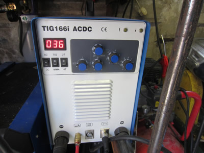
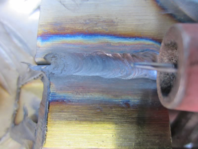
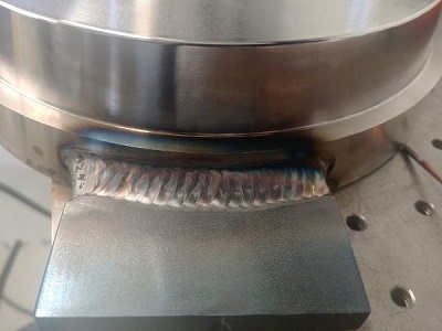
There are many different aspects to this type of welding which makes it so very complicated than just the standard stick or MIG method. Below from left to right shows the welder itself, electrode and a weld. I have completed many projects using a TIG welder, one of those included a turbo manifold and full stainless exhaust system for my car. TIG is my favourite type of welding since it is clean, silent and produces amazing welds.

Aluminium Welding
Aluminium is probably going to be the most reactive material that will be welded manually, but it's not all that difficult. It is probably the only common metal that will be welded using AC (alternating current). The reason for this is due to the oxide that forms on aluminium, when current passes in the positive direction is removes the oxide but heats the electrode, when it passes in the negative direction it applies heat to the work piece. If there is not enough positive to scrub the oxide then it gives a dull weak weld that is very awkward to build with filler. If there is too much positive then it causes the electrode to melt and little heat is put into the work piece. Usually its between 25 to 50% positive scrubbing, I use 50/50 most of the time which gives a very acceptable weld.
The big trouble with welding aluminium is it's conductivity. A lot of power has to be used for aluminium initially to get a weld pool going, but as the metal begins to heat the weld becomes faster. There are a couple of ways to keep a consistent speed weld. One of those is to pre-heat the work piece, one is to turn down the power as you go along, or the best option is to use a foot pedal that can vary the output power of the welder. I usually turn down the power or just speed up my welds. Aluminium is one of those materials where the weld is weaker than the previous metal, this is because aluminium retains heat when cooling softening it, aluminium can also get a bit too hot which changes its properties also. If aluminium is being used for a load bearing application then it must be heat treated to replenish some of the properties that it lost.

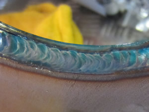
 To the far left is a picture of an ok weld, the right is a weld that got a little too hot, its slightly weaker and cosmetically worse, although ok for most applications.
The better the weld, generally the shinier it is due to the lack of impurities. I don't really enjoy welding this material and it can be difficult to get cosmetically great results, as can be seen in the pictures.
Stainless Welding
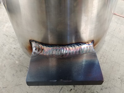
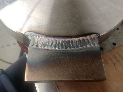
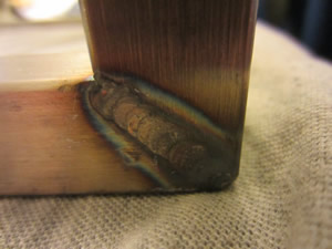
Stainless is quite an easy material to weld, very similar to steel. Unlike aluminium it requires a DC current as does most other metals. The TIG torch is connected to the negative terminal and the ground to the positive terminal, this is the only way it can work, the positive terminal is the side that creates the heat. If it were to be connected to the torch then it would simply melt the electrode and put no heat into the work piece. Below are some examples;
Stainless requires a bit more attention when welding due to oxidation possibilities. Hollow parts often need an argon purge to stop oxides from forming on the inside, these can become restrictive and even damaging to systems since they are very hard. Stainless can show a variety of colours when welded which aid the welder in knowning if temperature and gas flow are correct.


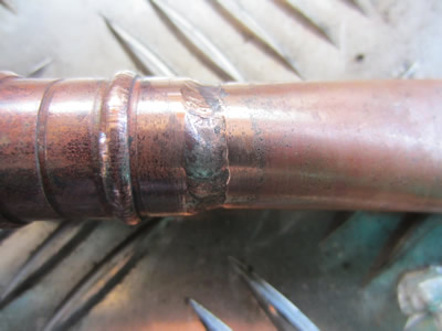
Copper Welding
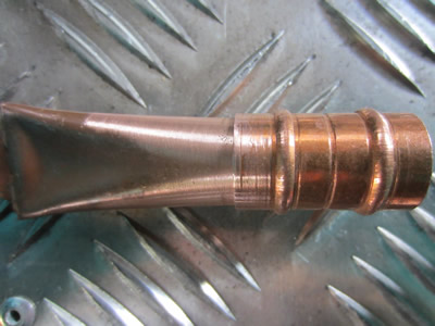
Copper can be quite awkward to weld due to its high conductivity and exhibits similar traits to aluminium welding. I didn't have a lot of copper to trial, so instead I used a little bit of plumbing pipe. Copper forms a black oxide very quickly when heated but can quite easily be brushed off, it seems to be quite easy to weld though.

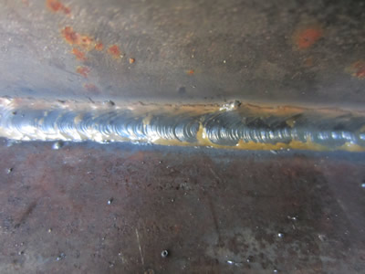
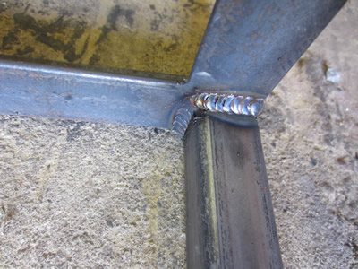
This is the easiest type of welding and is used for medium thickness materials. The main metals to be welded are steel, stainless and the less common aluminium. The Mig welder contains a spool of wire, when the trigger is pressed on the welding gun it pushes out this wire combined with a shielding gas - more commonly Carbon Dioxide / Argon mix. The wire hits the work piece creating a circuit (an earthing wire is connected to the work piece), the current melts the wire and the work piece creating a weld. The shielding gas displaces all of the oxygen out of the welding atmosphere, this stops the molten metal from oxidising which would lead to a messy and weak weld. With MIG welding it's mainly just a case of point and weld, there is a little bit of skill to setting it up and welding thin material but it's very easy to get the hang of it.
I have MIG welded a huge number of projects, most of those being tables or shelving. MIG welding is my go to when I need something done fast to a high standard, it is however the noisiest and requires the bulkiest equipment.
Here are a couple of examples;

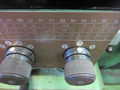
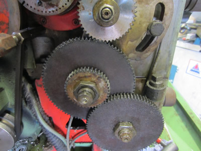
I prefer manual turning over CNC as you can get a feeling of the stresses on the work piece and the tool allowing myself to make changes if necessary. I'm not going to explain every aspect of this machining because basic turning is straight forward. What I am going to demonstrate is thread turning, something like a two start thread. The purpose of a multiple start thread is so that the pitch can be coarse while keeping the thread grooves shallow.
Firstly the correct pitch has to be chosen, from the grid on the lathe it says that I need to select "L2" and use the "G" gearing.

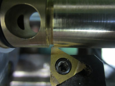
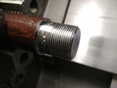
The next part is to turn down a piece of material, in this case brass, down to a diameter of 18mm. The final diameter of the thread will be 17.8 to 17.9, the final amount will be taken off by the threading tip, hence the name "full profile" tip. The next step is to use the correct size of tip and make sure that it's perpendicular to the work piece. A lot of demonstrations show the use of a thread plate in which there is a cut-out which is pressed against the inserts tip, the opposite side against the work piece, it should be parallel. In my opinion it's a rubbish method as the tip of the insert is so small, instead I press the insert up against the chuck which I know is a parallel surface and perpendicular to whatever I'm holding. I then make sure that there is no light showing along the length of the tip, as shown in the middle picture (not parallel) to the right picture (parallel).


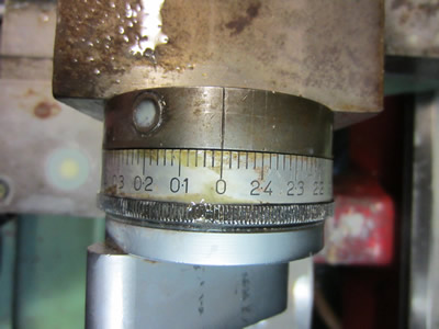
There is a little step on the insert which will start to take material off the final diameter, I set the tip to this point, zeroing the cross-slide. I then know that when I reach the zero the threads are at the correct depth, any further will start to take material off the outside diameter, I then go a further 0.2mm to bring it from 18mm down to 17.8mm, a further spring pass at 17.8mm is taken. Before all of this the compound is set at 0, very important. The lathe is started and the half nut is engaged at a chosen number, for me number 2 always engages and disengages nicely. The carriage will then move quickly towards the chuck, the tip will score the pattern of the thread onto the work piece, the half nut is disengaged very quickly when it reaches a groove (shown in the first picture). Many more passes are taken until the cross-slide is at the zero point, as mentioned earlier.
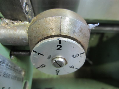
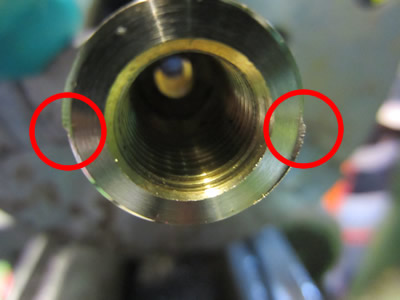
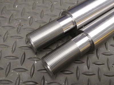
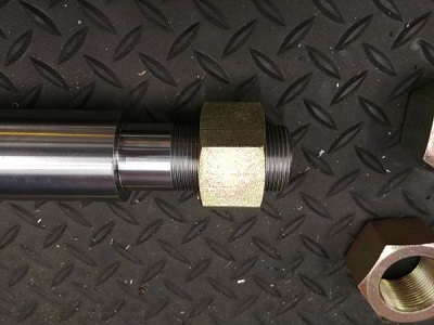
The first thread is now complete, the compound is now moved in by 1mm to offset the next thread by 180 degree as its a two start, 2mm pitch. I replicate the process above until the second thread profile is complete, the two starts are shown by the red circles in the last picture. This process only took me just under three minutes.


Just a little video to show how quickly a two start thread can be made, it is M18 x 1.0ISO with a 2mm pitch. The focus isn't great, but it gives you an idea of how quickly I can produce a thread.
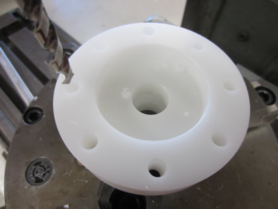
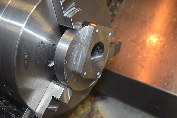
Manual milling is generally quite easy, the only difficulty may be how to hold the work piece. My current position at the time of writing this is a machinist on a CNC lathe, although my job does include manual milling as I'm the only one able to do it in my company. The materials are plastics and rubbers which can be very difficult to hold, it requires me to make elaborate jigs most of the time. Luckily most of the milling consists of a couple of holes and slots on the PCD of a ring, which requires me to work out the positions using trigonometry, find the centre of the jig using a dial indicator and then finally mill the whole thing. Below is an example of making myself a flange;
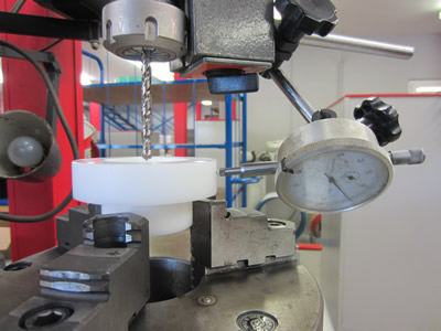
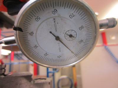
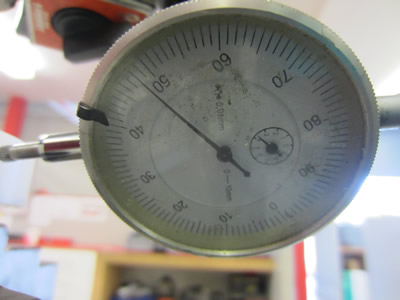
Firstly the part being machined is placed in a work holding system, such as an indexing head (or dividing head). The spindle is moved somewhere near the middle of the part being machined, a dial indicator is then placed against the work piece and then set to zero. The spindle is then rotated 180 degrees so that the dial indicator is pressing against the opposite side of the work piece. One dial shows 0mm, and one shows 0.48mm, this mean its center is offset by 0.24mm. One of the axis must be moved by 0.24mm, this process is replicated several times on each axis until the dial indicator does not move when the spindle is rotated, therefore no offset and central.

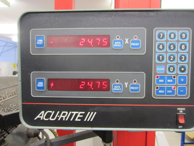
One of the pictures is the digital readout that the milling machine possesses, this makes it all very accurate. The readouts can be set to zero when the central position is found, then through a series of coordinates the holes can then be drilled. Milling is very simple, so I'm not going to do anymore explaining.
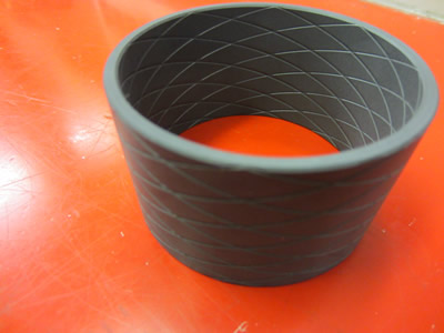
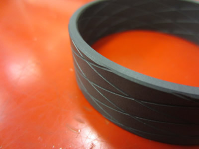
Please note that I don't own this machine, but I was given permission at the time of recording (2015). At the time of writing this I'm working as a machine operator, so why not demonstrate my programming knowledge, this is the easy part, the skill is machining exotic materials which I cannot demonstrate without you seeing it in person. For my demonstration it is the manufacture of a bearing ring made from a glass / moly filled PTFE, using the single threading action command G32 to produce grooves for oil lubrication, G76 is not suitable.
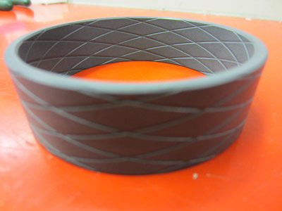
I made two rings, one at 40mm high and the other at 20mm high (as shown in the video above).
The program utilises the G70 and G71 commands for the roughing and finishing cycle, only on the ID as there is little to remove on the OD. The snippet of code for the inside is as follows;
G50 S2500
G96 S400 M04
G00 X53 Z2 M16
G71 U4 R1
G71 P10 Q20 U-4 W0.0 F0.2
N10 G00 X66 Z0.5
G01 G41 A225 Z-0.5 F0.1
Z-22.6
N20 G00 X53
G70 P10 Q20
G00 G40 Z10
After the roughing the G32 cycle is then used to create the grooves, a total of 8 forward and 8 reverse screw cuts. The snippet below showing two of the forward cuts on the outside, one at 0 degrees and one at 45 degrees
G50 S120
G04 X2.0
G00 X69.5 Z10
G32 Z-21 F100 Q0
G00 X72
Z10
X69.5
G32 Z-21 F100 Q45000
G00 X72
Z10
and so on
The program could not be sped up any further due to the limitations of the machine, even running at this speed the spirals are not at a feed of 100.
A piece of code I really like with the fanuc is the way it does threading, see this code for example;
G00 X1.8000 Z0.5
G76 P020060 Q0050 R.003
G76 X1.3886 Z-2.5000 P0500 Q0070 F0.0833
G00 X1.8000 Z0.5
Here is an example of the thread cut with this program.
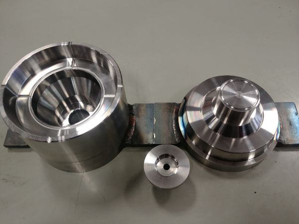
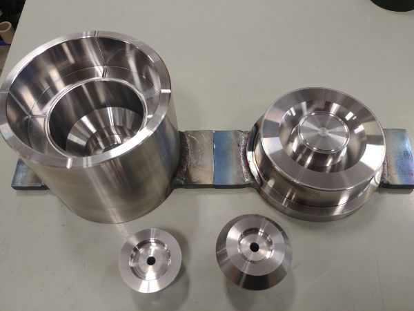
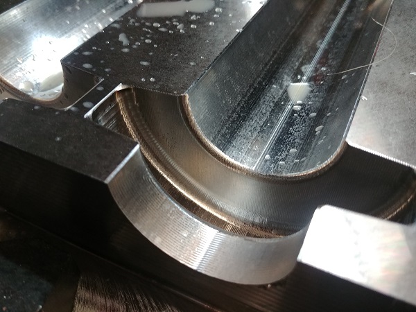
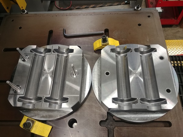
Here are a few more examples of moulds I have machined from 4140HT, a mirror finish required on all surfaces.
Please note that I don't own this machine but I have the permission for personal use at the time of writing this (2017). The current machine I'm using (at the time of writing this, 2017) has the Sinumerik 834D control panel, the machine is a 300mm throw, 12 station live turret CNC lathe. Since I can do so much on this machine I will only demonstrate a small portion on this page but I have created plenty of projects in the metalworking section that display what this lathe can do, unfortunately I don't have CAM software so I have to manually write all the programs.
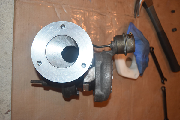
Here is an example of an adapter that I designed for my car. It attaches the standard exhaust manifold to a turbo T28 manifold. Due to the close proximity of the turbo to the alternator I had to create an offset, this required a lot of time in programming. Using variables I created a looping program that milled the conic hole, it only used around thirty lines of code and made a total of 80 passes. It was quite the task since I chose to make it from bright steel so required a lot of roughing programming. The end result worked out perfect and my car was converted to turbo using this piece.
Here are a couple of examples of milling, these are all done using CAM software. This particular part below was designed by myself to be used on my car. It is a spacer for the intake manifold to allow for a second rail of fuel injectors. This part worked flawlessly and helped me double the stock power of my car, that can be seen in my Hyundai Tiburon Turbo Project.
This mill used a Centroid control which is almost like a cheaper retrofit system. The machine control failed to boot and I purchased the mill at a later date with the intention of rebuilding it and the control system to use on my own projects.
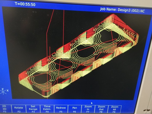

These are examples of using a much more modern mill with a tool changer. These are moulds completely machined from 4140HT, the diameter being 12 inches.
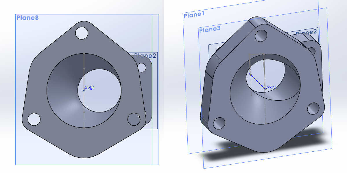
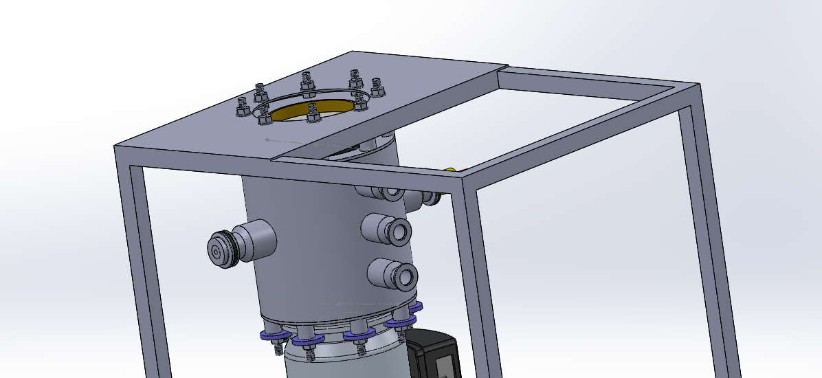
The current version of Solidworks I have access to is the 2016 version (time of writing this, 2017). I use this software a lot, especially when I need to program something in the CNC at work. I won't go into too much detail here because simply looking through my projects you will see I use it a real lot. Here is an example of an assembly for a project I am / have been working on.
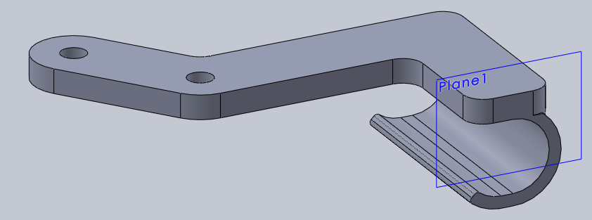
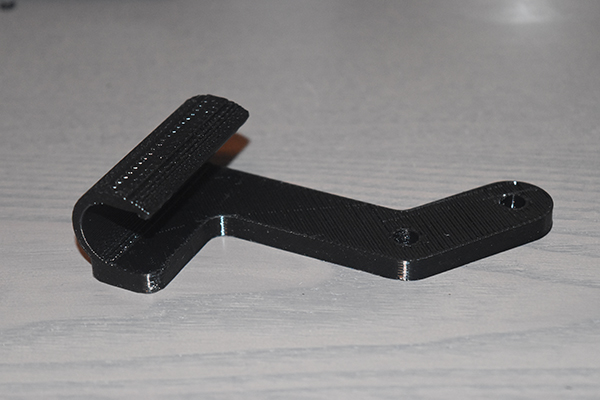
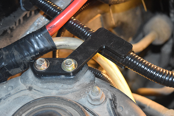
Fused deposition modeling is an example of the 3D printing we all know. In basics it's just how a brick house is built, layer by layer. A hot nozzle much like a glue gun extrudes plastic from it's tip, it is quickly cooled by fans to solidify it. A part is built layer by layer, each subsequent layer is bonded by the heat of the nozzle. The part such as that below may be built in layers of 0.2mm, that means that 100 layers need to be printed if the part was 20mm high. Here is an example of a part I designed to hold a cable in the engine bay of my car.
3D printing is a slow process which means that it will unlikely replace current manufacturing techniques, however for one off parts such as this it is invaluable. This part took around four hours to print and probably cost about as much as a grape, I don't think any other process could have beat this in both speed and cost for a one-off.
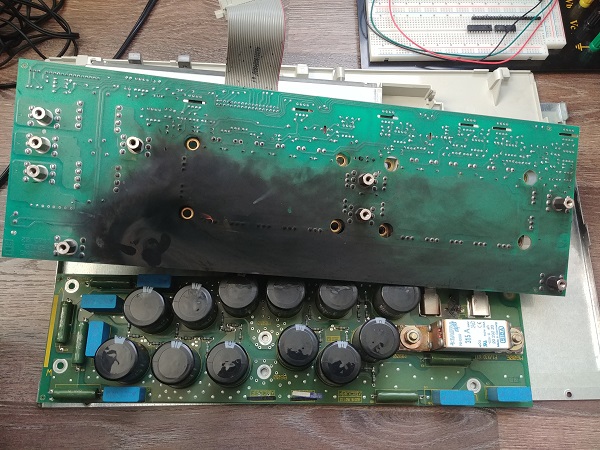
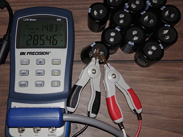
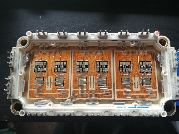
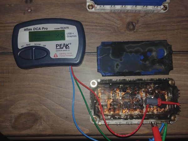
These are such projects like fixing welders, power supplies, vehicles and appliances. I admit that I enjoy doing this kind of thing so much that I tend not to record them or even label them as a project. Please take a look under the miscellaneous link under projects, there are a couple of examples. Here is an example of a CNC drive that I fixed. This I wrote a diagram from the layout of the PCB, removed components to check their condition and life expectancy, and made vital repairs.
PLC - Programmable Logic Controller
Admittedly I haven't had a huge amount of experience with PLC's, although I have owned one in the past to perform simple tasks. The great thing with PLC programming is that generally the programming is pretty universal, normally ladder, the only downside is that some require specific software tied with their manufacturer. I've had limited experience with the instruction list style of PLC that's programmed on the module itself, basically when I were at college and a one off outside, these are rather rare now.
I learnt the ladder diagram method at college using GX developer, quite recently I managed to get hold of a PLC which was programmed using the same software. I suggested an application for a friend in which I programmed the PLC and sold it to them. I did not record the program, but hopefully I shall be buying another one very soon. A great thing about the Mitsubishi PLC's is that they have a great PDF that shows everything you need to know on programming, so much so that I think even with no prior experience one could have one functioning in a day or two.
Note to self: example of the program.
Below is a simple program that illuminates an LED for a small amount of time when a button is pressed. Check out some of my other projects for more complex programs. I do also have some projects solely on programming microcontrollers with assembly and how. Unfortunately assembly is no longer used, but it gave me valuable experience. I used this knowledge to quickly learn C in which I continue to use for all my programming projects.
There is quite a large variety of basic programming softwares, the one I have used a lot is called PicAXE. The purpose of a basic editor over something like the assembler is that it is easier to learn for new time users, but it's a slower operating system as it needs to be translated into it's machine code operating language first. I used to use it for simple programs like the one below, but now C is a much better alternative.
This program is what I used on one of my air rifles to measure the air pressure via a pressure transducer and then to display this measured pressure on an LCD. It starts by setting the chips operating frequency to 16MHz, then a long pause to allow the display to initialise itself. The program then outputs the word "pressure", a numerical value and the word "bar". The chip then reads a 10 bit analogue value from the transducer, some calculations are made and then the value is displayed when the program loops around.
Start:
setfreq m16
Wait 16
Main_Program:
Serout b.0, T9600_16, (254, 01)
Serout b.0, T9600_16, (" Pressure ")
Serout b.0, T9600_16, (" ", #w0)
Serout b.0, T9600_16, (" bar")
readadc10 b.5, w1
wait 4
let w1 = w1 - 204
if w1 > 1500 then goto let0
let w0 = w1 / 4
goto Main_Program
let0: let w0 = 0
goto Main_Program
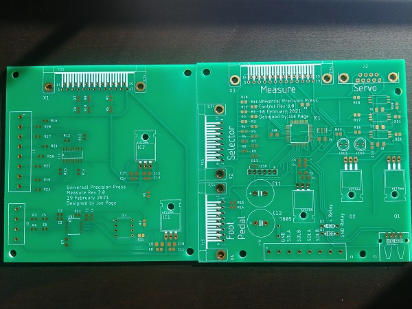
Printed / Prototype Circuit Board
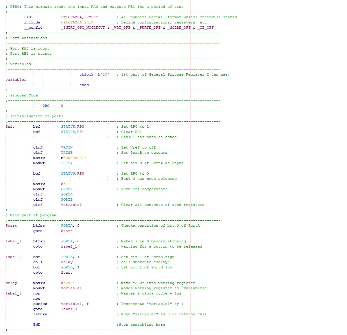
Some of my projects that I put to use are placed on a circuit board, under the electronics section in the projects shows how to manufacture a prototype board. Here are a few examples of boards I have created, most of those in the examples are chip adapters, LCD serial drivers and a few specialised boards for my lambda AFR project and the 50kV switch mode power supply project.

A quick update, I am now able to create doubled sided boards and utilise surface mount components to decrease footprint. Here is an example of a board I designed and built, it is a fuel controller for a car.

This particular board below was designed, etched, populated and lacquered in around 8 hours. This board is a 3-phase controller for a 170V, 1kW brushless servo motor.
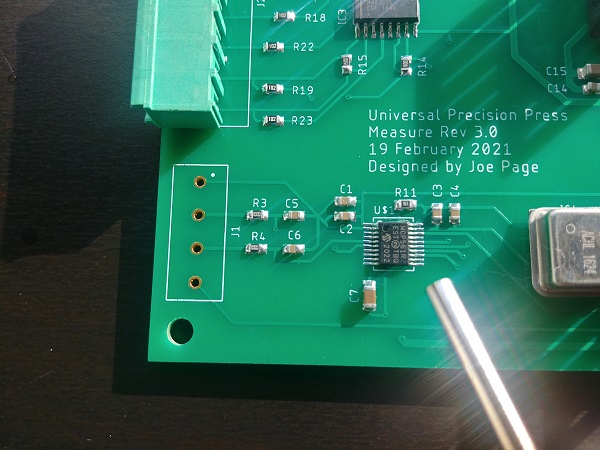
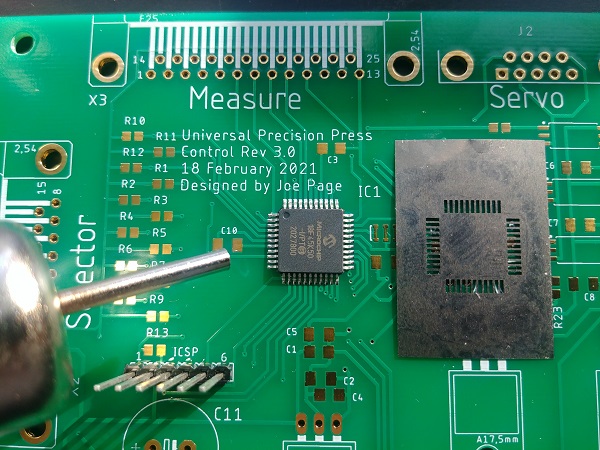
I used to like the idea of building my own circuit boards but the process is rather tedious. I do even have a PCB mill that I'm building a tool changer for in another project. Without purchasing lots of chemicals it is very difficult to replicate a professionally made PCB, especially hidden vias. Here are some boards I designed for a product and had professionally made.
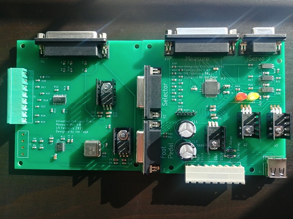
I should also note that I am fairly skilled in soldering and rework. Here are a couple of examples, the smaller is a 20SSOP.
Electromechanical Design / Fabrication
This is what I truly enjoy the most, in reality this what nearly all of my projects are. Please take a look through the project page, you'll see that most projects go through the; design, prototype and build stage. I am saving this section for a special project I'll be doing in the future.
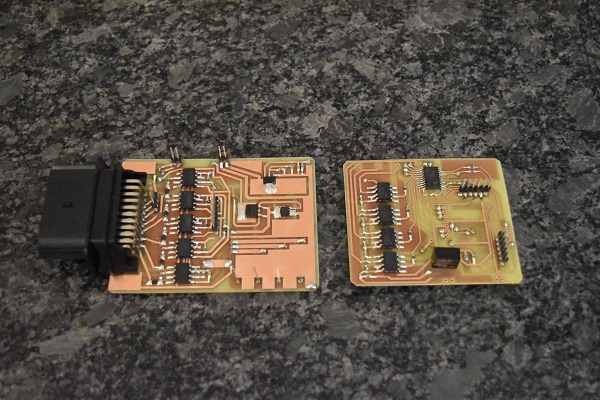
I build a lot of projects that involve the use of electronics, the majority of it being based around microcontrollers. There are quite a few large projects I've built that I'm pretty proud of, these have required a lot of time and planning. I will leave the larger projects to be searched within my website, here is a particular build I did for an acquaintence. It is the complete control system for a CNC engraving machine with A-axis (4 axis). I built the whole thing from scratch including the case which I painstakingly drilled and filled all the holes for the connectors. This would be a production machine so I used a high quality supply and drives. The only thing I did not source myself was the drive for the spindle since this was supplied with the machine. This was quite a simple project because it mostly consisted of wiring and assembly, I did not have to make any boards or program any chips.
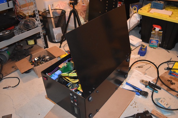
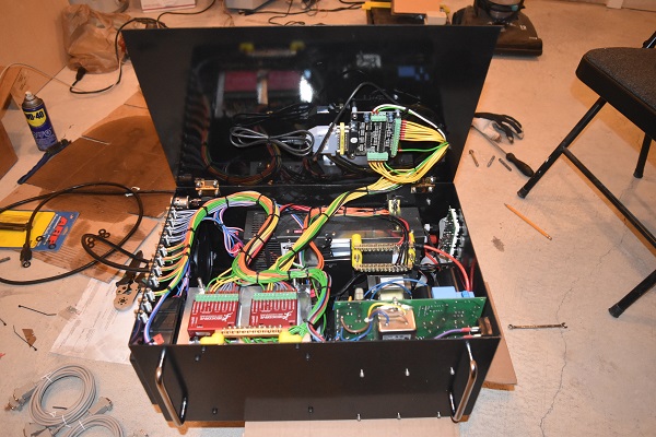
The project was very successful in that it worked flawlessly and was accurate.
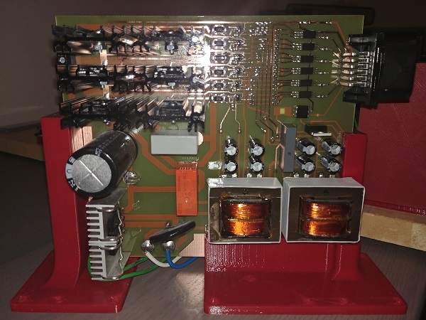
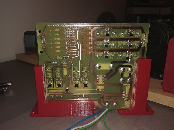
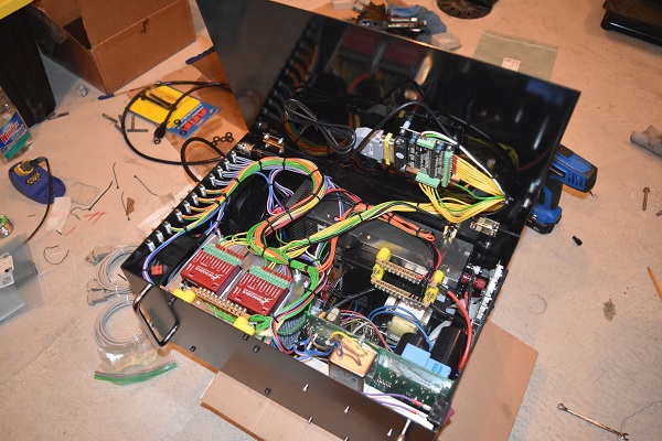
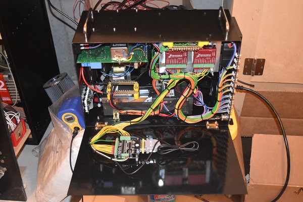
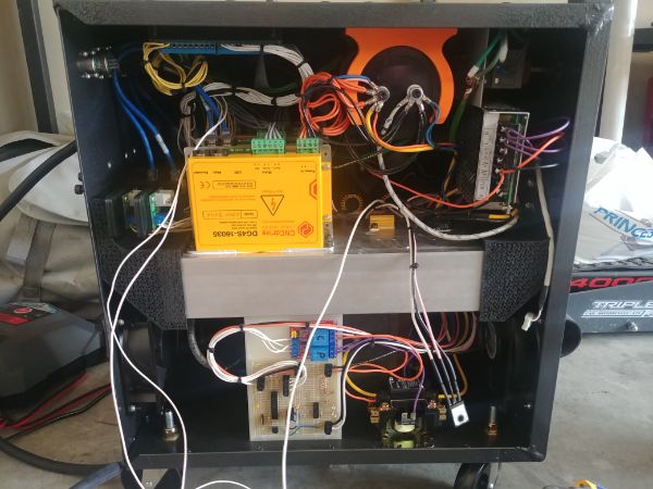
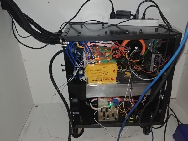
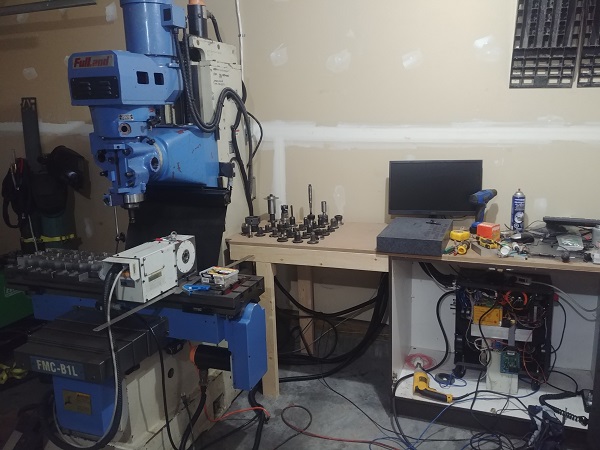
Another very similar project I worked on was to design and build the control system for a CNC milling machine. This was a personal project for an industrial machine for home use. The machine originally ran on 3 phase with an out of date control system that did not work. I build a unit that controlled four servos, the spindle speed and all worked from a 220V wall outlet.
I used solidworks to model the design of the unit.
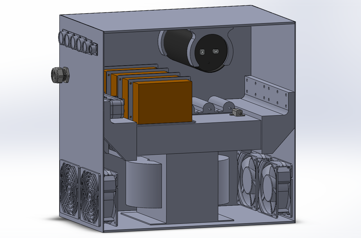
The unit is not quite finished in the pictures below but it worked out great. I currently use the machine to build my own projects. I built a simple dynamic braking circuit that would discharge the bus capacitor if the regenerative power became too much. I also added a circuit on the board that would charge the filter capacitor up first before connecting the power relay.
Note that I will not show my address, contact number or where I received my education unless an employer asks for it.
Email: edwardproj@hotmail.com
Career Objective:
I have a keen interest in electromechanical devices, focusing on how they operate and troubleshooting of repairs. My future career objectives are to design, prototype and build such devices, to be a valuable asset to my employer by continually expanding, furthering my knowledge and education in the profession of electromechanical engineering. I would consider any position that will utilise my skills and abilities from the simple repair of workshop equipment to the design of aerospace projects.
Skill Summary:
Skilled at working under pressure, performing multiple tasks at once and highly motivated and committed to delivering first class quality work. Very experienced in using CNC lathes by Fanuc/Siemens controls, CNC milling, manual milling, manual turning, drilling and grinding machines. I have the experience of machining a various number of materials including polyurethanes, nitriles, stainless, aluminium, cast iron and even titanium.
I also have the ability to use oscilloscopes, signal generators, PAT testers, insulation testers, ESR meters, various electrical tools as well as all basic hand tools. I am able to MIG and TIG weld a various number of metals and have an excellent understanding of the equipment required to do the job. Excellent people and teaching skills, I have taught apprentices from no knowledge of measuring equipment to being able to read drawings, program a CNC lathe and carry out a high standard of work independently.
I mostly work in a logical way breaking things down into smaller sections / components. This gives me the ability to troubleshoot, repair, maintain or rebuild anything with either the basic understanding of it's construction, operation or even just by breaking it down. With this attribute I have been able to repair and service a wide variety of objects such as; cars, motorcycles, welders, CNC lathes, domestic appliances and many more with the aspect being either electrical, electronic or mechanical.
Computer literate including using design software such as National Instruments Multisim, Solidworks, Autodesk AutoCAD, Siemens Solid Edge, Adobe Photoshop, MPLAB IDE, MasterCAM, but give me a manual and I can learn to operate or repair anything. I'm also able to write assembly code for advanced microcontrollers and basic html for websites.
Full clean car license, including the use of a vehicle to commute.
Education and Achievements:
Open University Maths and Physics Degree - currently 33% complete.
Student of Excellence Award – College 2011 - Awarded by the Institute of Engineering and Technology.
Student of the Year Award – College 2010.
BTEC Extended Diploma in Electronic and Electrical Engineering Level 3.
16/17 distinctions achieved.
Overall grade: DDD – 360 UCAS points.
2009 – 2011.
GCSE’s:
Mathematics - A, Double Science - A, A*, Electronic Products - A, Geography - A, English Language - B, English Literature - B, ICT - Pass, Adult numeracy and literacy level 2 - Pass.
2003 – 2009.
Employment Experience:
Tool and Mould Maker
November 2018 to Current (Same place as below)
I returned to work here when my residence application got approved. My main responsibilities are to machine moulds for rubber compression moulding. I design specialised tooling for machining plastics efficiently and accurately. I also fabricate anything which may save us money, this has included machine platforms, walkways, stock racks, machine modifications and painting extractors. I am considered the fastest and most skilled machinist, I am often taken from my post to machine products the other machinists can not. I designed a composite spring energised seal with a crimped steel casing, manufactured the dies and completed the product in just four hours. Within 24 hours the seal had passed testing, this quick turn around landed us a large customer account. I have often gone beyond my responsibilites in terms of fixing machinery, liasing with customers and designing custom seals to meet their specification.
CNC Machinist
January 2017 to May 2018 (Work Visa Expired)
My main responsibilities were to machine plastic parts from a customer drawing. The parts were often to strict tolerances and some also required live-tooling. The main machine I used had a Siemens Sinumerik control in which all programs were done manually. I used Solidworks to aid in programming but also to create a CAD file for our Zeiss CMM. I am also able to program a Zeiss optical and probe measuring machine.
In my second year of employment I started in the venture of compression moulding. This was something new to me and the company which required a lot of initiative to get things working. In this process I had to make an extraction system covering 3 x 4 metres, design and build the electrical system for a rolling mill and design and build a vacuum chamber for the moulding process. I will also be starting in mould design and manufacture, this however requires more machinery before I can do so. I have also spent a great deal of my own personal time practising my CNC programming and machining skills on the lathes after work. A lot of time has also been spent on thinking of ideas how to improve our processes, one of these included saving the company 30% in material costing.
Self-employed Mechanic
October 2015 to April 2016
I chose to do this as a filler between leaving my job and departing to Canada, mostly for my self interest as I made little money off this venture. I mostly repaired and maintained motorcycles and cars, in a few instances some domestic appliances and a couple of welders, the electrical aspect of those two.
CNC Machinist
April 2011 to September 2015
My main responsibilities were to machine hydraulic and pneumatic seals by the use of a CNC lathe – Fanuc Controls. Job involved the setting of tools, making tools, programming and running the machine. I was considered to be the most proficient machinist at our company which lead me to be given complex programming jobs that I had to machine from my interpretation of a drawing, normally requiring me to make tools and shape carbide inserts. I was the only machinist able to mill plastic, rubbers and urethanes.
I have taught several apprentices, most of them having never used a micrometer/vernier or even seen a lathe to being competent independent machinists producing quality work.
I also repaired a jewelry laser welding machine by dismantling it, tracing wires and diagnosing the fault on a component level. I de-soldered the original part and installed the new one, saving the company a repair bill of £1600. I have repaired all of the CNC lathes by diagnosing the fault, ordering a new part and fixing the machine, this had become a weekly habit.
Quite commonly I was asked advice on suitable equipment for the shop floor, I were also required to design parts. I designed a cycle testing unit to measure an allowable pressure drop and count how many cycles a seal would last until it failed, it featured an LCD and a programmable user input.
I decided to terminate my employment to move to Canada.
Interests and Activities:
My main interests/hobbies are designing and building electronic and mechanical devices.
I built up my own workshop to include a lathe, milling machine, TIG welder, MIG welder and many other tools to build a variety of projects. Some of these have included an engine rebuild, a model plane engine, a forge, induction heater, nuclear fusor, and many more. I have my own electrical workshop and have built various projects such as an electronic air rifle that the user could select power, all designed and machined by myself.
For my GCSE project - age 15, I designed, prototyped and built a working burglar alarm with LCD display, keypad, reset-able security code and motion sensors. For my college project - age 17, I designed the electrical and electronic system for a complete CNC lathe. I converted a none-working lathe from three to single phase and updated its computer and control systems.
I have so many interests it would make boring conversation for me to list them all.
I use this website to record my projects and achievements.
References
These would be available upon request.