18 Series - Chapter 15 - SD Card Part 2
In the previous chapter I discussed how to initialise the SD card and how to read and write to it. If the card only needs to work as a simple storage device then this is ok, however if you want to deal with media then you will need to work with a file allocation system such as FAT32. In this chapter I will discuss a little bit of the boot sector, the directory system, how to read and write a file. The programming will be as basic as possible but ideally I would need to write out a simple operating system.
Master Boot Record / Partition
The first accessible line of data in an SD card will start at something like address 8192 but in a HEX editor such as WinHex you will not see these first 8192 bytes and it will in fact say sector 0. When in reality reading from sector 0 will actually require address 8192, in general this offset will take this value but of course a computer needs to be certain as it can take other values.
The file system I will be using is FAT32, my SD card has been formatted to 32kbyte per cluster. There's no need for me to explain the whole FAT32 structure, all you need to know is that at the very beginning of the SD card is what is known as the partition, not all hex editors will be able to read this, I downloaded an editor for free called "Disc editor". What most editors will read is something called the "FAT Boot Record" , it contains important information, the location can be found from the partition. The FAT boot record is then required to tell use where the "root directory" is, this is a list of locations to where the data is to be stored.
There are a few things first which should be known. Firstly a sector consists of 512 bytes, this is set and cannot be changed. Each bit in the SD card command address corresponds to a sector, therefore single bytes cannot be written or read, only in multiples of 512 byte sectors. A cluster is a multiple of sectors, for example my SD car has been configured to 64 sectors per cluster, this is written into the FAT boot record. Lastly all of the SD card data, not our file data, follows something called "little endian", the data is read backwards, so byte 1, byte 2, byte 3, etc...
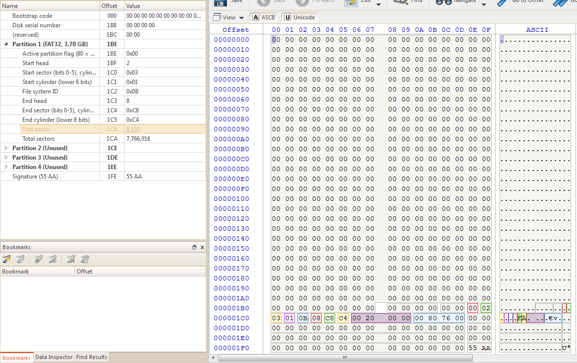
Below is an example of the partition, the software does a great job of decoding what all of these bytes mean. The only part of data that we need is the location of the first sector, so we would read from address zero and then continuously read and discard the data until we reach bytes 0x1C6 through to 0x1C9. The first sector is known as the boot sector, this is where most HEX editors will start from, without reading the partition we would be unable to accurately reach this point. The data read is 00 20 00 00 which is actually 0x00002000, following little endian, this corresponds to 8192 decimal.
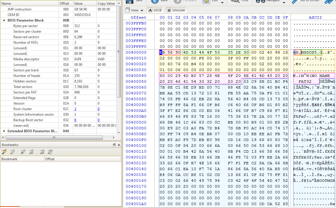
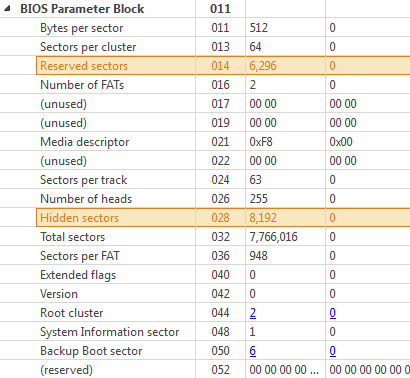
After finding the start of the boot sector we need to load this value into the read command, so loading 8192 into the SD cards read command will bring us to the boot sector. Here is an example of the boot sector, the main things we need to read from this are, the bytes per sector (this should always be 512), the sectors per cluster, the reserved sectors, the hidden sectors and the sectors per FAT. You may notice the offset in the software can be calculated by sectors x bytes per sector, 8192 x 512 = 4194304, 0x400000.
To find the start of the root directory we use the formula, "Hidden Sectors + Reserved Sectors + (2 x sectors per FAT)". So using the formula I would get 16384, loading this into the read command would bring me to the root directory as shown in the example below. The root directory contains entries relating to the files saved on the card, each entry takes 32 bytes.
The root directory entries have the following protocol, remember little endian.
| Root Directory Entry Data Structure | |
|---|---|
| Bytes | Description |
0 |
First character of the file name in ASCII, or allocation status 0 = unallocated or E5 = deleted entry |
1 to 10 |
Remaining characters of the file name |
11 |
File attributes, see following table |
12 |
Reserved |
13 |
File creation time (tenths of seconds) |
14 to 15 |
File creation time (hours, minutes, seconds) |
16 to 17 |
File creation date |
18 to 19 |
Last access date |
20 to 21 |
High-order cluster offset |
22 to 23 |
Modification time (hours, minutes, seconds) |
24 to 25 |
Modification date |
26 to 27 |
Low-order cluster offset |
28 to 31 |
File size |
| File Attributes | |
|---|---|
Byte Value |
Description |
00000001 (0x01) |
Read-only |
00000010 (0x02) |
Hidden File |
00000100 (0x04) |
System File |
00001000 (0x08) |
Volume Label |
00001111 (0x0F) |
Long File Name |
00010000 (0x10) |
Directory |
00100000 (0x20) |
Archive |
Taking the first entry from the root directory,
![]()
The entry has been deleted, the file is called "001", the file is an archive, etc... You may also notice that some data is missing such as a the cluster offset and the size of the file, the reason is that this is a deleted file. The following is the actual file, we can see this time that the file is about 17kbyte long and the offset cluster is 3. In the boot sector there was an entry called the "root cluster", it's value was 2, it will always be 2.
![]()
The root cluster is referring to the root directory, so when the cluster offset in the entry above says 3 it means that it is the cluster after the root directory. Our root directory is cluster 2 and our file is in cluster 3. The root directory has the sector address location 16384, since there are 64 sectors per cluster it means that our file is at sector 16448. You will find there are a great deal of entries relating to your file even if you have only ever saved one copy, only one of them will be valid, a disc clean up tool such as a defragmenter will remove these obsolete entries.
Filing System
The filing system is one of the difficult parts when integrating an SD card into a project just because the amount of code required is so large, if reading data is the only concern then this simplifies things a great deal, if writing files is on the agenda then a great deal more is required. For this chapter I will only be dealing with a small number of files, filing the root directory is where things complicate slightly and this is too much for now.
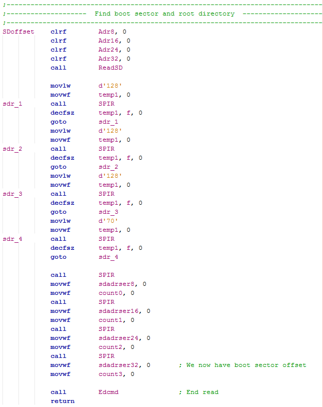
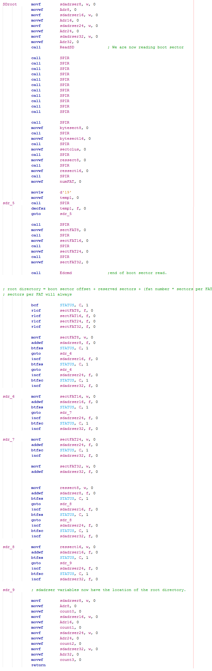
So we know how to find the boot sector and then the root directory, the first step is to create a program that will read the SD card and arrive at the root directory. The below program first loads address 0x0 into the SD card and then reads from it, a total of 454 bytes are skipped in order to reach the data that tells us the address offset, the values are saved into variables, they are also saved into variables that are used in my BCD program that converts the data into decimal to be displayed on the LCD.
Once the address offset is found this can be loaded into the SD card in order to find the boot sector. This long section of program will pick out the important parts of the boot sector and then finally make a calculation in order to find the location of the root directory. Again at the end of this section some variables will be loaded to be processed by the BCD program to allow the user to see this address if necessary on an LCD.
Read Directory / Read File
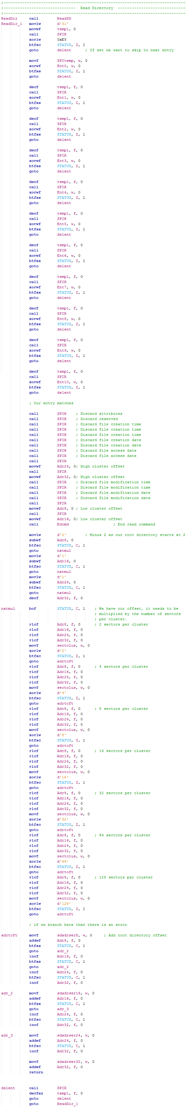
There are two options, read and write. To do either of them you will first need to read the root directory which will contain many 32 byte entries. The difference is that when reading we will be searching for an entry, once the entry is found it's address is loaded and the file can be viewed. The difference in write is that the root directory is saved, then modified, then overwritten including our new entry, then the file is written.
This long section of program compares the entry we want to find with what's in the SD card, once found the address offset is extracted and added to the addressing system. The file is ready to read.
Read Example
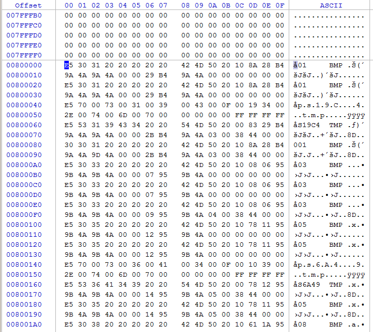
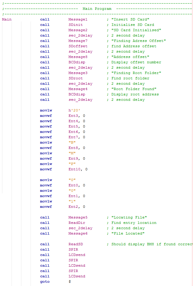
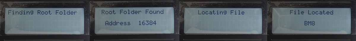
The following is a little section of program that calls up subroutines and outputs some messages to the LCD. So it first initialises the SD card, finds the addressing offset, then the boot sector, the root directory and then finds the BMP image 001. At the very end the program reads the first three bytes from the file, it receives BM8 back which is the standard first three bytes in a BMP image file.
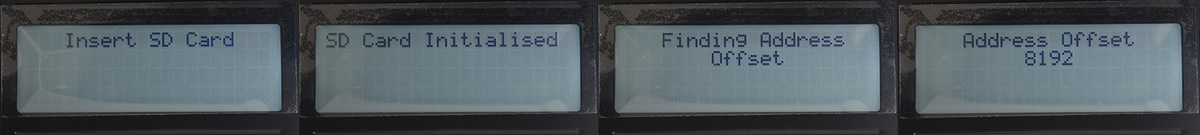
Here is an example of the images produced by the program.
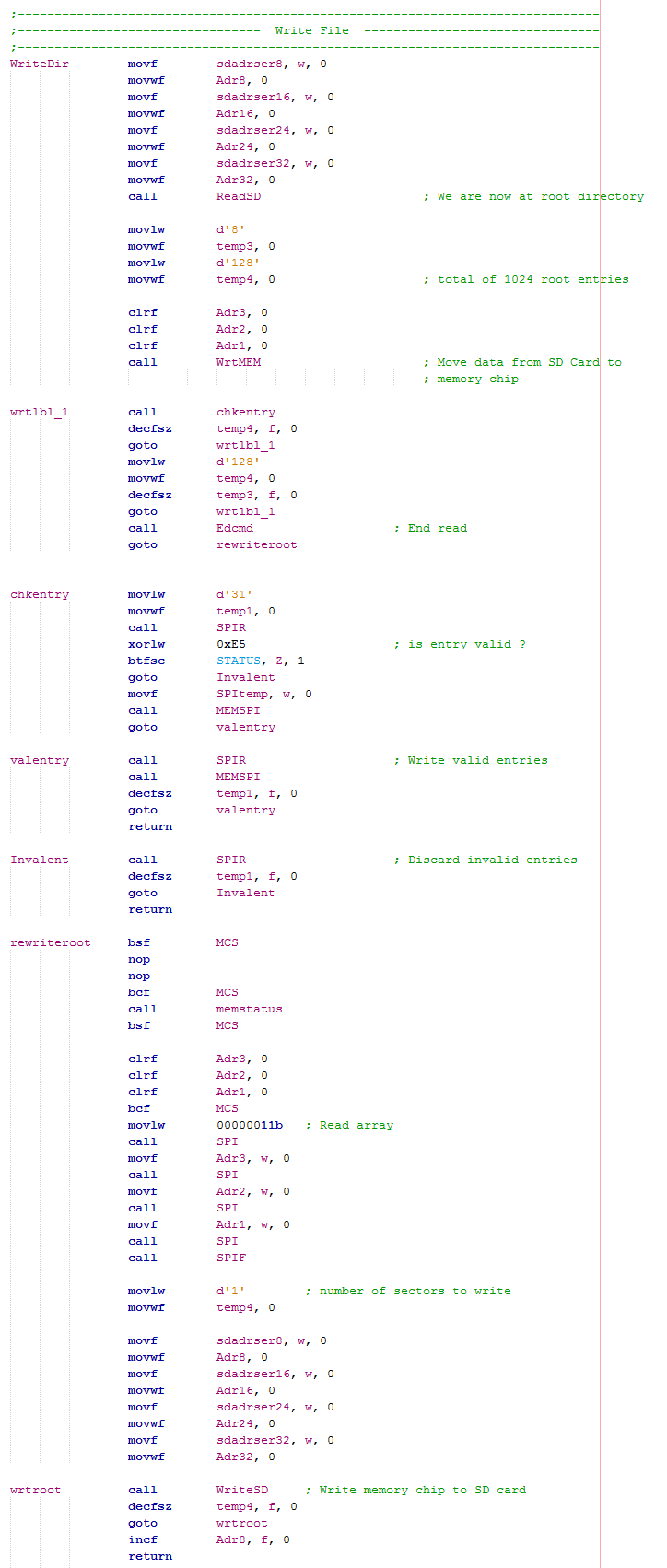
Write Directory
The difficult part when dealing with an SD card is writing to it due to the fact that it has an addressing structure that has a larger capacity than the microcontroller. So for example if I want to write a file it means that the root directory must be modified, this being 64 x 512 bytes long means that an external memory chip should be used, something like SRAM. Since speed was of no concern I chose to use the flash chip I used in a previous chapter.
This first section of program will read the contents of the root directory and place them into the flash chip, it will continue for 64 sectors. The root directory contains a large number of invalid entries, these will be ignored, the end result will be some de-fragmentation. It is not proper practise to delete all the invalid entries, in fact when an entry is added to the root directory all it does is add it to the latest sector, the whole root directory doesn't have to be re-written, all I'm doing is cleaning up the folder so I don't require multiple root directories.
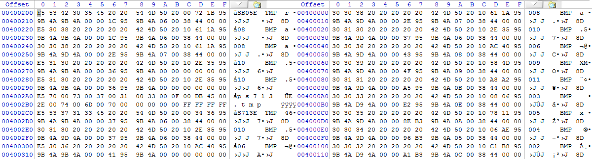
The above program has read the root directory, removed the invalid entries and saved the valid ones. Below shows the result, an original example on the left and a cleaned version on the right.
FAT 32
So what if I want to add an entry, well this is where things start to get a little more complicated. Firstly you need to know what the entry will be called, some data about it and finally where it needs to be written in the SD card. This is where the FAT system is used (file allocation system) The 32 stands for 32-bit, there are also 16 and 12 bit versions which are pretty much obsolete and unused in the modern world. The most commonly used version is the exFAT which is a 64-bit version.
At the beginning of the SD card right after the boot partition is something called the FAT's, there will be two of them, the second is a copy of the first to help reduce the possibility of corruption.The FAT tables show all the possible clusters and what state they are in, whether they can be written to, occupied or part of a chain of clusters. In FAT32 there is a 28-bit addressing system, each bit represents a cluster and therefore a maximum possibility of about 2TB.
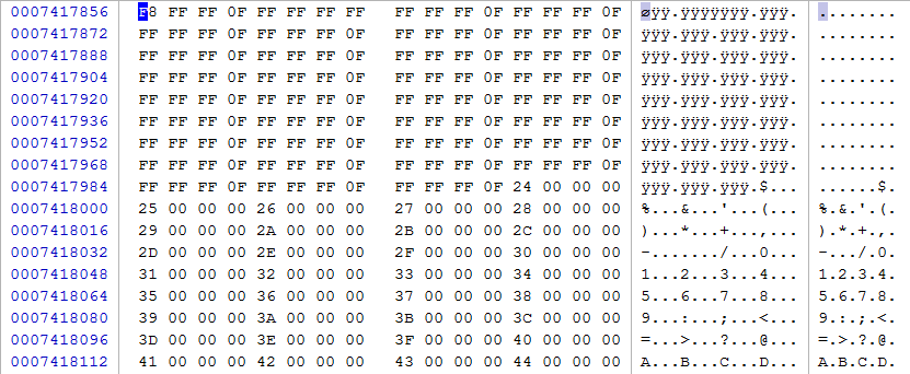
The first thing to do is find the FAT and see how it works, here is an example of my SD card, this contains many single clusters and also a long string of clusters.
So how is it found, this is very simple, it is the number of reserved sectors plus the number of hidden sectors. This equates to 14488, this is the address of the first FAT, the second FAT is this number plus our sectors per FAT, it would be 15436. Straight after the second FAT would be the location of our root directory, so 15436 + 948 = 16384 as expected. I have already written a program that finds these values and loads an offset with the contents.
The main thing is to work out what our FAT actually means, how it is to be decoded. Remember that everything is little endian, the reason I have put this column into the table. Also remember that our FAT 32 is actually a 28-bit system, this is the reason for the ? as this nibble is not needed, it can take any value but more commonly it is zero, it should never be F.
| Cluster Value - Hex | Cluster Value - Endian | Description |
|---|---|---|
| 0x?0000000 | 00 00 00 ?0 | Free |
| 0x?0000001 | 01 00 00 ?0 | Reserved |
| 0x?0000002 - 0x?FFFFFFF | 02 00 00 ?0 - FF FF FF ?F | Multiple Clusters |
| 0x?FFFFFF6 | F6 FF FF ?F | Reserved |
| 0x?FFFFFF7 | F7 FF FF ?F | Bad / Corrupt |
| 0x?FFFFFF8 - 0x?FFFFFFF | F8 FF FF ?F - FF FF FF ?F | Last Cluster |
The first two entries (zero and one) are F8 FF FF 0F and FF FF FF FF which states the last cluster, these mean nothing and can be ignored, remember the root cluster number was 2, this is due to these first two pointless entries. The root cluster starts at entry 2.
The second entry is FF FF FF 0F which states that it is a last cluster, it can either mean that this is an only cluster or the last in a chain of clusters, either way it doesn't matter. This is the root directory that only takes one cluster.
The third entry is again a last cluster, it is one of my image files that only occupies one cluster.
Entry 35 is the following, 24 00 00 00 which can be determined as part of a multiple cluster. This is an address corresponding to the decimal number 36, this entry says that the next entry in this chain can be found in entry 36. If entry 36 was the last in the chain then it would be FF FF FF 0F. A multiple cluster entry is just a pointer to the next, also remember that each entry (apart from the first two) correspond to a cluster.
Last is an example of the root directory, imagine that it exceeds a cluster and that it must take two. The second entry would transform from FF FF FF 0F to the location of the second root directory, the second root directory would then be labeled as FF FF FF 0F as it is the last of the chain, if there was a third then it would change to the location of the third and so on. With this type of a system you can end up with many scattered clusters but there is logic, for an SD card it doesn't matter if there is defragmentation as it only slows the system by a miniscule amount, however in a mechanical hard drive this can add up to some substantial time.
Writing a File to an SD Card
This is the procedure to writing to an SD card.
~ Determine number of clusters required for file.
~ Find the first available cluster and the second, place first as an end cluster if only one is required otherwise write the location address of the second cluster, continue for however many clusters there are and label the last as an end cluster. Keep a count of the number of entries you had to skip through in order to find your first available one.
~ Find the first possible line to write an entry in the root directory, name it and ensure you place the offset which is that of the FAT entry counter.
~ Write the file into the chosen clusters from the FAT folder.
Overall this is a huge task and requires a lot of programming, too much for this particular chapter, you should however check out the projects for the 18 series of microcontroller because I will create this system.
Reading a File from an SD Card
This is the procedure of reading from an SD card.
~ Locate the file you wish to read in the root directory, take it's offset data.
~ Use that offset data to find the file in the FAT and all the other files associated with it. Take all of these offsets and store them.
~ Place the first offset plus the root directory offset to find the first cluster, read all it's data and repeat the process .
Even reading from the SD card is quite a task requiring quite a large storage of memory.
Here is a copy of the program so far - Program Text.
The SD card is a very important part of the modern microcontroller project, I personally use them a lot. This chapter has briefly covered the basics on how to read and write to the SD card, the next project will deal with the transflective graphic display and use the SD card to display an image. On a side note I have created a project called "SD Card Controller / Programmer", this project allows the user to view the contents of an SD Card, modify, defragment, transfer data from one card to another and also outputs both EUSART and SPI. An additional part I added to the project was the ability to program memory chips as these are a frequent part of my projects.
Hello, if you have enjoyed reading this project, have taken an interest in another or want me to progress one further then please consider donating or even sponsoring a small amount every month, for more information on why you may like to help me out then follow the sponsor link to the left. Otherwise you can donate any amount with the link below, thank you!