18 Series - Chapter 17 - OLED Display
The graphic display is quite an asset to a project but it can only work in monochrome and it has a slow refresh rate of only about 5Hz. The next step up would be an OLED display that works on LED technology, it works fast and allows 4-bit colour. I have started to use quite a few of these displays in my projects just simply because they are a little easier to work with. On this page I will discuss two OLED displays, one is 128x64 and the other is 256x64. Both of the displays are OLED and are from the same manufacturer however they use different controllers which makes quite a difference in the programming.
OLED Display
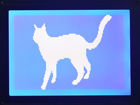
Firstly I will discuss the OLED display as it differs quite substantially from the graphic LCD. Below is a comparison of the transflective graphic LCD of the left and the OLED display on the right. As you can see one does at best a silhouette whereas the other represents an image. The OLED is an example of the grayscale type which displays a total of 16 different shades of colour, yellow for this example.

The major difference with these displays is the data that is supplied to them, you will quickly find that the OLED is more difficult to setup than the LCD. The LCD works on a system of rows, each row is eight pixels high, each pixel represents a bit, therefore one byte will write eight pixels. The display needs to be directed which row and where to start of that row, it is very flexible due to it's pointing system allowing the user to write single characters without affect the rest of the display. Forget all of that for the OLED.
The OLED works pixel by pixel, the data in determines what colour that pixel is. Since grayscale is 4-bit it means that our 8-bit in represents two pixels. If we were dealing with a colour OLED then one byte could represent up to 256 colours, or four bytes could also represent just one pixel using the RGB table. Since I will be using grayscale we are stuck to two pixels per byte.
With the OLED display a series of commands and addresses will outline a write area, the area is filled line by line, no additional commands are required to increment the pointer. There are two options with an OLED, the first is to completely write the image every time the display needs to be updated, this would of course require 4k of RAM which we simply don't have. Note that the terminology for a temporary storage of data is known as a buffer, so we would require a 4k buffer. The other option is to only update our area we wish to change. I do use both of the methods depending on my application, the buffer method is the most common practise but it is slower.
Hardware
For the first half if this project I will be using the 16F887 microcontroller, it's a 16 series, the reason is because part of the information on this page is valid from a previous 16 series chapter. The first half is based on the OLED as shown at the beginning of this page, it is 128 x 64 pixels in size, it also requires 3.3V.
This particular OLED uses the SSD1325 driver which allows me to run either two different modes of parallel or two different modes of SPI. Since the SD card will be using the SPI slot I chose parallel interfacing, I could have used both SPI however this would greatly complicate and slow down the program due to a lack of microcontroller RAM. An SD card reads 512byte blocks, now imagine we can only hold 128byte on our microcontroller, that means we would have to read the first 128 bytes of the SD, swap to OLED and send the data, then read SD again, skip the first 128 bytes and now read the second 128 bytes, back to OLED, then back to SD, etc... Using the SPI for the SD allows us to directly send data via parallel to the OLED.
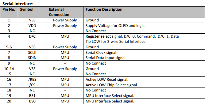
Here is the pin diagram for the OLED display. As you can see it is very similar to that of the graphic. One major difference between this and the graphic is the working voltage, it must be 3.3V. There is little need to read the display so the R/W pin can be tied to 0V. The reset pin is not often needed, it is good practise however to pull the display in reset mode until the power supply settles. Chip select is not required for parallel, CS is pulled to 0V.
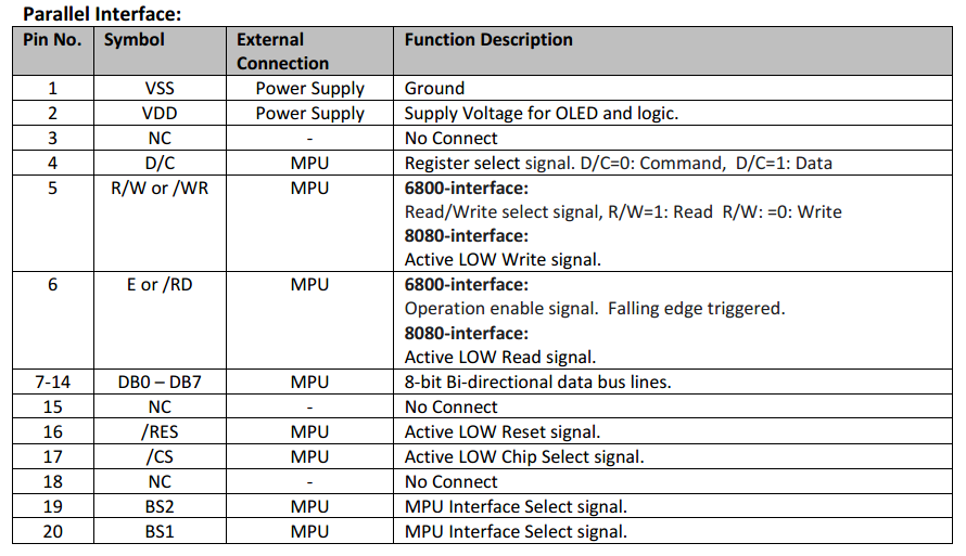
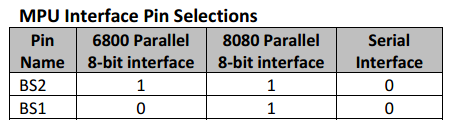
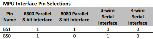
The last two pins control which interface we want to use, I will be choosing 6800 mode as this is the parallel we are used to. I would not recommend 8080 parallel as it's a little more complicated to use and for me there are no benefits over 6800 mode. 6800 mode allows us to select between read / write with the R/W pin and between data and command with the D/C pin. Data is clocked by a pulse of the enable pin, the falling edge clocks the data.
Software
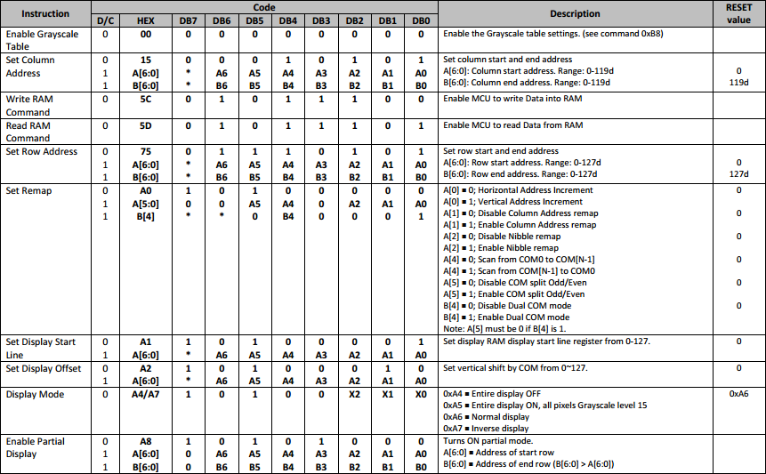
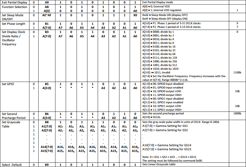
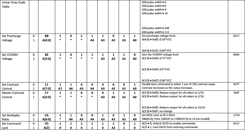
This part is not all that difficult but like with most displays there is an initialisation procedure. There are two instruction tables for this particular controller, the second which I have not shown deals with pixel configuration such as the grayscale values or precharge voltage levels, stuff that's unnecessary to change, for now.
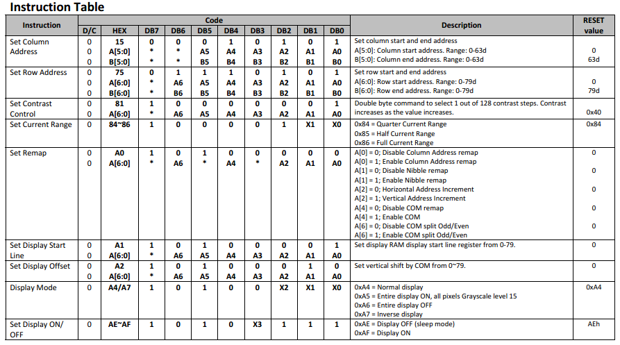
Set Column Address - The controller is designed for a 128 x 80 size display, however it is possible that we don't want this size or we only want to write to a specific section of the display, this command allows us to set the edges of our write area. Since my display is 128 pixels wide I simply write command, then zero and then 63. Note that each column consists of two pixels, hence 63.
Set Row Address - Similar to the above except we are dealing with rows, my display starts at row 13 and ends at row 76. With these two commands you can write anywhere on the display however this is not the standard way of doing things, a completely new image is normally sent instead.
Set Contrast Control - The standard contrast is a little dim but ok for most purposes, increasing the contrast will increase the current consumption, you may also find that increasing it too far will loose colour depth in the image.
Set Current Range - This is very much linked to the contrast and will determine how bright the pixels are, it is best to set this at the maximum otherwise the display appears too dim.
Set Remap - This is a very important setting as it controls how the pixels are to be written to the display, as you will notice the display starts writing at the bottom left corner and writes line 0, then 2, then 4 etc... I will show how this is to be configured in my program but basically by changing the com/split bit to one, this allows us to write line 0, 1, 2 etc... We then set Com bit and Column address bit which starts us writing in the top left corner like a normal display.
Set Display Start Line - The line we want to start at, after changing the remap we are really starting at line 76.
Set Display Offset - This will offset the start line, after some tweaking this turned out to be 9.
Display Mode - I find this mode to be a little pointless, all of the other options should be done with data and not the settings of the LCD. Inverting the pixels may be useful, I have however done this in my program as it will be required.
Display On - Yes
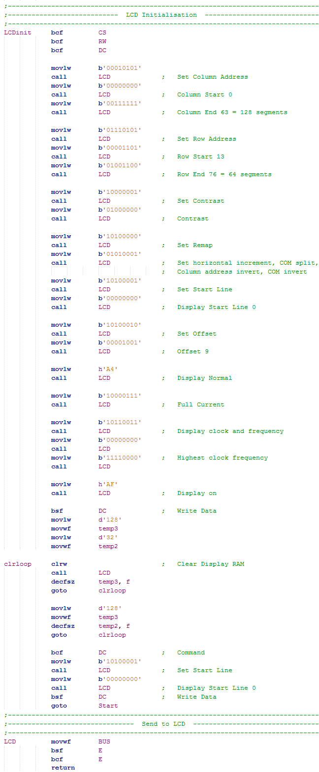
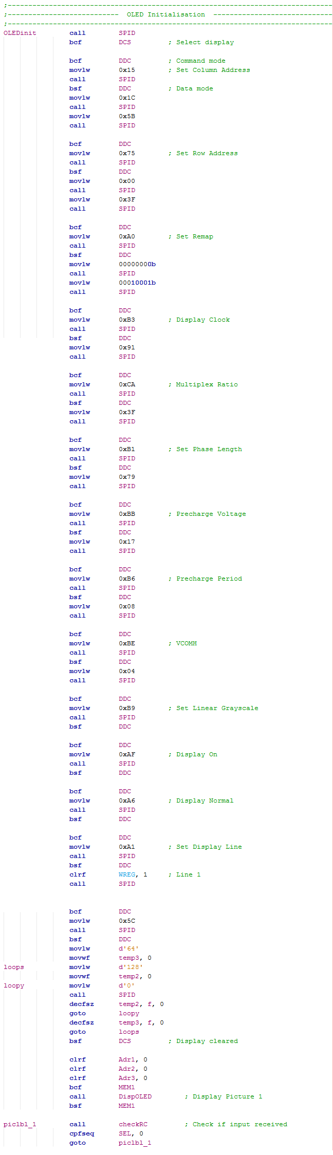
Initialisation Program
This OLED will work straight out of the box, the only command required is to switch the display on, an initialisation process is required for your application and for you to set the displays boundaries. Note in my program I have used LCD throughout, an OLED is not an LCD but it makes my program much easier to read by using the term "LCD".
A different OLED
The other OLED display I used in another project is based on the SSD1322 controller and is 256 x 64 pixels in size. You would assume that these displays would work much the same but that is not the case. First to show is a pinout diagram for the SPI configuration, it is exactly the same as what the SSD1325 controller is, for both parallel and SPI.
The first difference however is how the different modes are to be selected, the four wire SPI remains the same but the parallel interfaces do not.
The largest difference is the command set which is pretty large. The major difference is that a command is sent in command mode but the data for the command is sent in data mode. This actually makes a little more sense than the SSD1325 controller since the command and data is all sent in command mode, I think the reason is probably because this instruction set is larger and it reduces the chances of errors.
The initialisation stage is always different for a display, a lot will also depend on lighting conditions and the available current to the display. Here is the initialisation procedure for this display, at the end it also clears the display and then presents an image to the display.
To display an image it is up to the user whether they use an SD, a memory chip or the internal data on the microcontroller. It must be noted however that an image will use (256 x 64) / 2 = 8192 bytes of data, for this project I chose to use external memory in the form of a flash chip. The program below will read the flash chip, the display area is set and the data is written. The subroutine at the end of my program swaps around some data to align the pixels in the correct order.
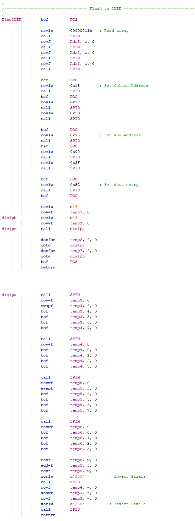
Another difference between the displays is how the pixels are written and how the column addressing system works. For the SSD1325 controller the column address represents two pixels, one byte of data equals two pixels and the pixels are backwards. with the SSD1322 controller the addressing system is four pixels, two bytes of data equals four pixels and the pixels are yet again backward, the last section of the program above is used to jumble these pixels in the correct order to be displayed.
Writing to a single Section
The project I have taken this data from is my user display for my car ECU, there are a few times where only a small portion of the display is to be changed. So for example I have some check boxes, the program first sends the image with the check box unticked, a separate program will then write into the square of this box, this saves a lot of time and memory. Below is the end result. You may notice there is some pixelation in the image, this is due to that my car can supply the correct current whereas my programmer cannot, I need to adjust the initialisation settings.
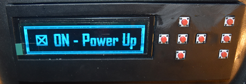
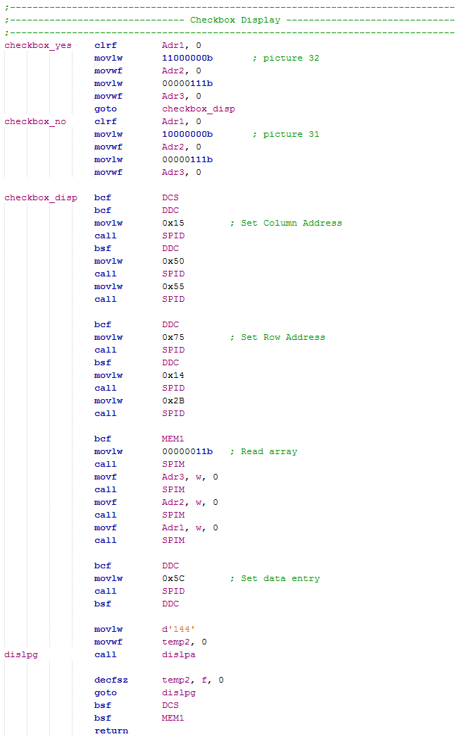
The program has two pictures to choose from in memory, the check box ticked and unticked. The column and row address is set to the position of where the check box needs to go, the memory chip is read and fills this area with the image data.
I hope this project has given a little insight in how to use an OLED display and some of the differences you may encounter between similar looking models. I have quickly skipped through this one but you may find many other examples of programming on my website including the use of OLED displays. I do intend in the future going through a lengthy process of explaining how to implement a colour OLED display into a project, I have not decided yet whether I will use the 18 or 24 series of microcontroller (16-bit).
I hope that these projects will have helped you to understand some of the capabilities of the 18 series of microcontroller and how you may be able to use some of the peripherals in your own project. Check out for other projects I do in the 18 series, other than that check to see if I have written some chapters on the 24 series as these are 16-bit and are even easier to use.
Hello, if you have enjoyed reading this project, have taken an interest in another or want me to progress one further then please consider donating or even sponsoring a small amount every month, for more information on why you may like to help me out then follow the sponsor link to the left. Otherwise you can donate any amount with the link below, thank you!