3D Printing a 4 Rotor Air Powered Wankel Rotary Engine
The Wankel rotary engine is probably one of the most unusual engines ever to make it into consumer production. While the engine originally made promises to be the future, it failed to perform. Nearly all the manufacturers in the 70's spent considerable time researching and designing this engine. Ultimately the engine was much poorer on emissions than the 4-stroke piston engine and plagued with reliability issues. DKW manufactured motorcycles with this engine to a moderate success, it was just as reliable as a 2-stroke but produced slightly more power. The engine had a power to weight ratio three times that of a 4-stroke engine which made it desirable for performance related applications.
Mazda was the only car manufacturer to use this as their only power plant, almost bankrupting the company. They chose to continue to produce vehicles with both the 4-stroke engine and the wankel. They successfully sold a car right up until 2012 with this engine before calling it quits. The engine never matched the long-term reliability and efficiency of the 4-stroke which was it's downfall. The engine is still very iconic and sought-after for some enthusiasts since it produces a sound like no other, it can produce an extremely high power to weight ratio and it is surprisingly robust at these high powers.
I want to design my own wankel engine first to run on air, this is that page. There seems to be two popular goals in terms of building a rotary / or as in being the first. That is the engine with the highest power to weight ratio, but more popular, the most number of rotors. Norton, Citroen, DKW, Suzuki and Mazda produced twin rotor engines for their production vehicles, Mazda being the only one to create a 4 rotor for use in racing, in fact their 787B with a 2.3L 4-rotor with 700 bhp was the first ever non-piston car to win the 24-hour Le Mans in 1991.
There was never anything more than a two rotor being sold to the public, however many enthusiasts modified the twin rotor 13B engine. 3 and 4 rotor engines started to become popular, and then a 6-rotor became the record for a long time. There are a couple of people out there machining their own engines from scratch based upon the 13B, someone building a 12-rotor built in a 3x4 configuration. Since I will be first building an engine to run on air it won't produce all that much power, or more importantly, it will allow me to build the worlds longest inline rotary engine. While making 7 rotors will be the record, I intend to increase that to 12 and then eventually up to 24. My fuel powered engine will produce considerably more power, so there is only so big I can make the drive shaft. Ideally I would like to make a 24 rotor in this configuration / I will make that engine.
I originally set out to make this 3D printed engine up to 24 rotors but settled on 4 instead. A 3D printer is simply not accurate enough to build one of these engines, or one with any kind of efficiency. I quickly found that to get an adequately running engine required a massive amount of air. The reason I had to reduce it down to 4 rotors was simply because I could not supply enough air to the engine. What is most valuable with this project is that I got my geometries right, which I can transfer to metal.
Design
There is a little bit of mathematics involved in designing an engine such as this. A long time ago I did the mathematics of a wankel engine on pen and paper along with a graph full of points to draw the rotor. I had to do a lot of searching around to find the mathematics to draw this engine again, plus I started with known dimensions of the Mazda 13B.
The 13B has an eccentric offset of 15mm with a 105mm rotor radius. The housing profile is known as an epitrochoidal curve and can be expressed as a parametric equation. Solidworks allows the user to draw a curve driven by an equation as shown below.
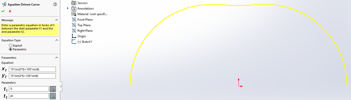
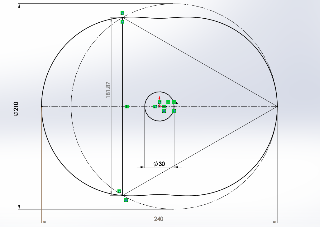
The curve can then be mirrored and then the rotary geometry drawn in. The inside of the housing works out to be 240mm wide and about 182mm tall. While I do not want to copy these dimensions it gives me an idea of how to draw the profiles. I am looking to make something around half of this size, now while I could probably scale it down I will instead choose my own dimensions.
It is not always a simple task of plugging in some numbers and the design is done, unless I go to great lengths to build one. For me the biggest determining factor for the design is the gears as bigger ones will be more forgiving when it comes to 3D printing.
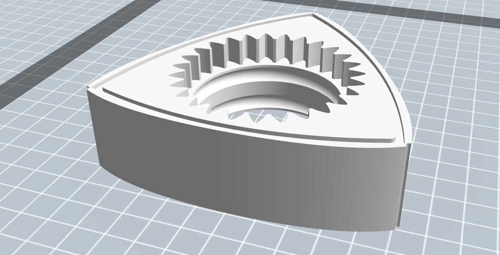
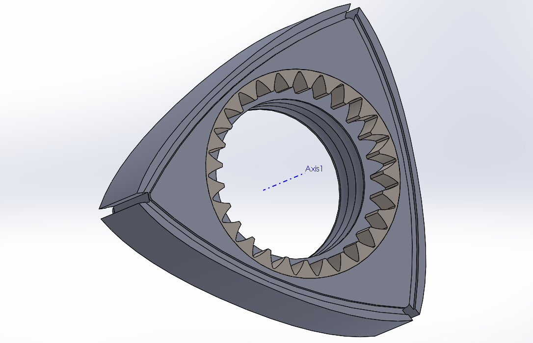
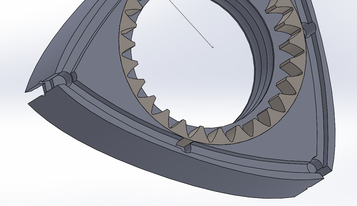
I will also say that for now I will not be showing any actual numbers of my design until I have achieved all of my goals, I don't want to put all this work in and someone beats me too it. Here is the housing and centre gear that I came up with. Now this process took quite a bit of playing around to get the numbers to match properly. The smaller gear has a ratio of 2 to 3 of the internal ring gear in the rotor. The 13B engine uses a 34 and 51 tooth gear which makes the teeth quite fine, too fine for 3D printing. Also note that the meshing diameter distance between the two gears needs to be equal to the eccentric radius. Changing the number of teeth and the module of the gears will change this value. In the end once I was happy with the gear ratio and distance it meant having to slightly modify the eccentric radius. In all this is what I ended up with.
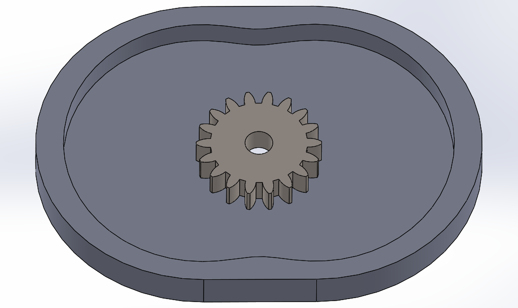
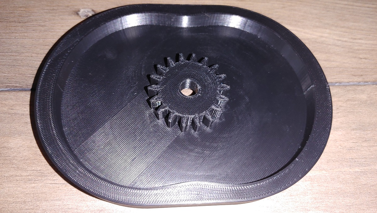
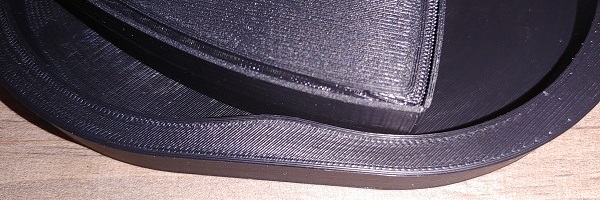
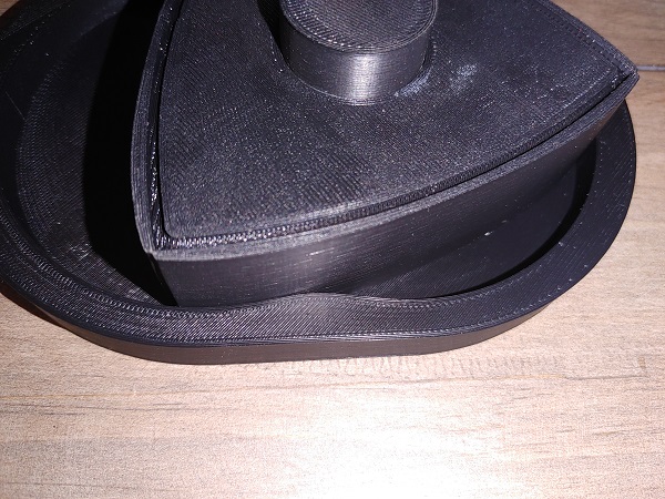
I then proceeded to 3D print this part as a visual demonstration to make sure I got all of the dimensions correct.
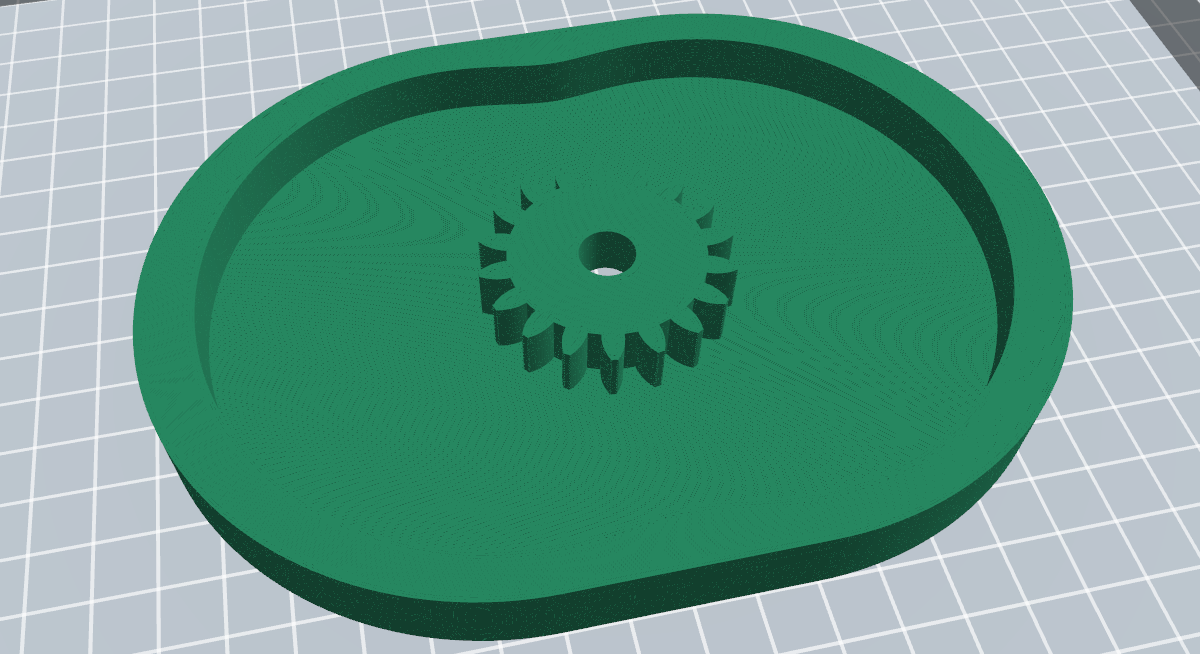
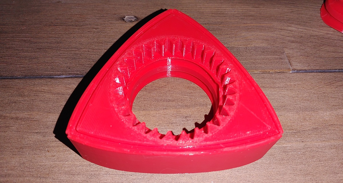
Here is the 3D print which I chose to make from ABS, just to use up some left-overs.
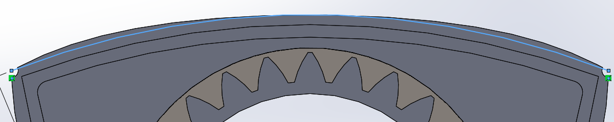
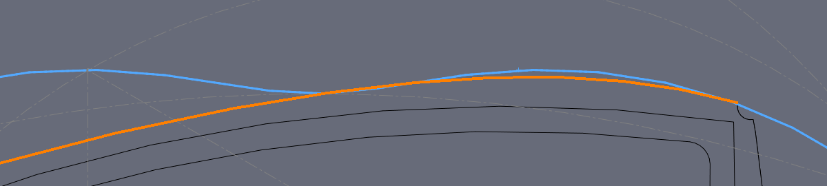
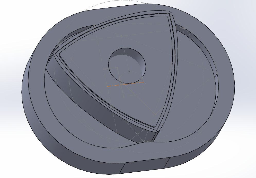
The rotor was a little bit more tricky as the outside profile was not a simple radius, that again a parametric curve. Here shows the sketch of my geometries with the rotor at two different positions. I have chosen the outside profile of the rotor to be a simple radius.
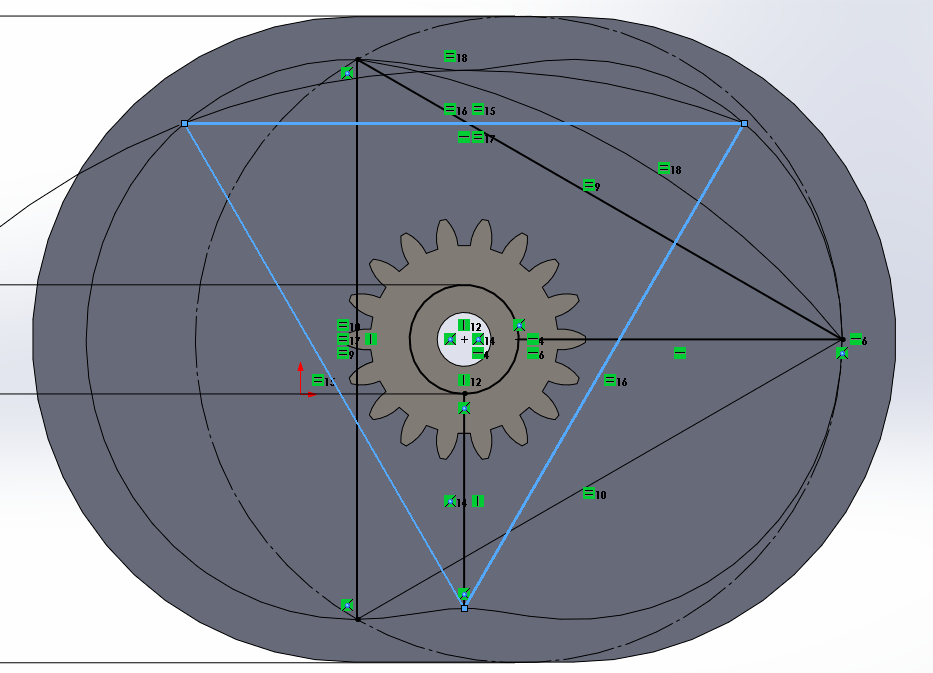
This is a close up of the radii of both rotors. You can see that the orange line is touching the housing, as it should be. The blue line is however not touching the housing, and therefore not the correct geometry for the rotor. This is not necessarily a problem with a gas engine, but definitely an issue with an air engine as we don't want air by-passing this gap.
I 3D printed a rotor along with an eccentric drive shaft. In the first picture you can see that there is no gap between the rotor and the housing. When the rotor is at any other position then this gap opens up, not the true Wankel design.
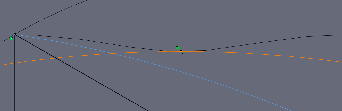
Now it took me a lot of searching to find the correct way to draw the rotor, thankfully it can be done with a parametric curve in Solidworks. Here below shows the original curve in blue and the rotor made to the parametric curve. The radius of the curve continuously changes and that is how the rotor stays in contact with the housing.
This is a screen shot of the assembly with the rotor at a random position, the curve of the rotor will always be touching the housing. This means that if the geometry of a wankel engine is correct then there will be five points of theoretical contact at one time. Realistically there will be contact with the apex's on the rotor to the housing and a very slight bit of clearance between the rotor curve and the housing.
Here is the rotor with the outer curve revised. I also included some grooves for O-rings to sit as these will do the sealing on the air engine, however I might have to revise the apex seals later on.
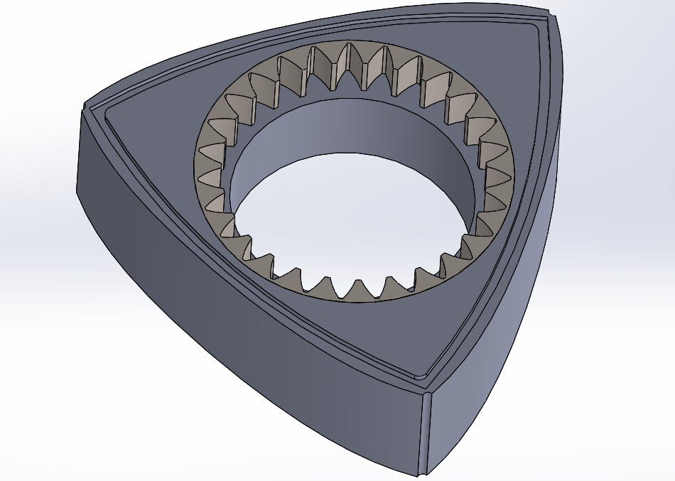
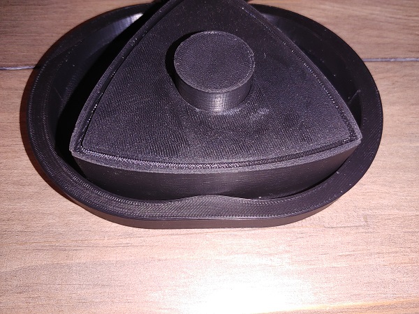
This is the final geometry of the housing profile and the rotor profile. I chose to 3D print all of these parts to ensure I got all the dimensions correct. Note that I did not extrude the housing all the way as to save some time and material.
This is my working model and shows the rotor in two positions. If there were apex seals in place then there would be 5 points of contact. The model spins over nicely and it seems everything is how it should be, this is one of my favourite prints yet.
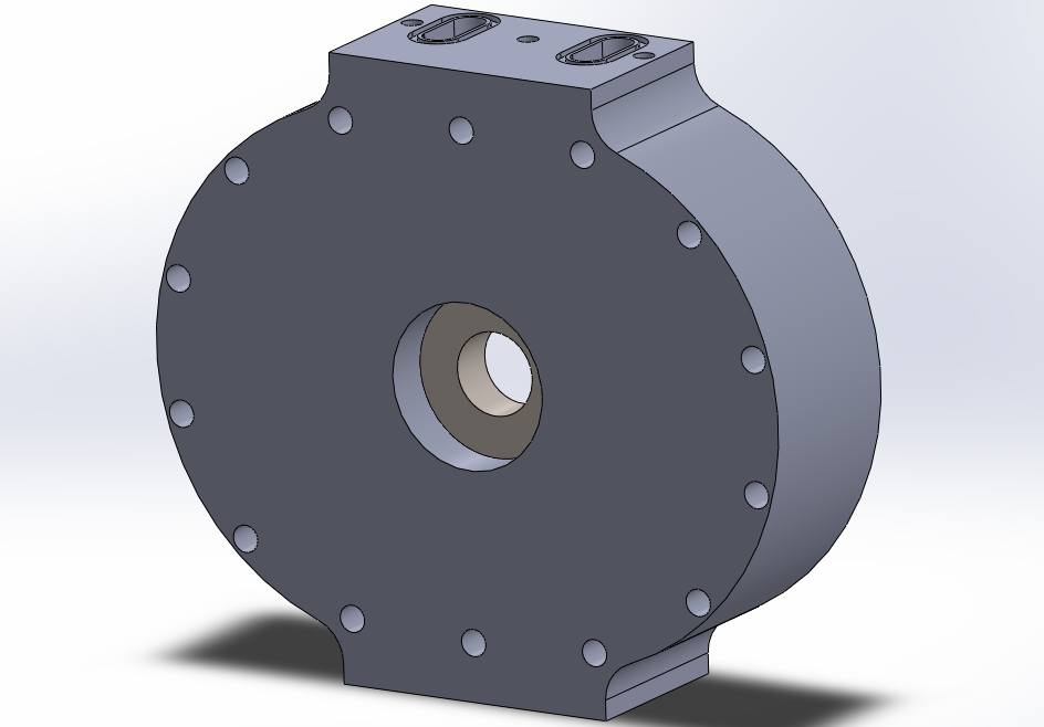
The next step would be to start on the actual air engine design, the one that I will be stacking. Now the air engine operates slightly differently to one that runs on fuel. For one there is no combustion and secondly there is no compression. The air engine has twice the number of inlet and exhaust ports which means it also has twice the number of power cycles than the fuel engine. Note that with this design I also want to make it with the intention of machining it from metal and with little modification make it run on fuel. So I have to consider the fitment of bearings for both the drive shaft and the rotor.
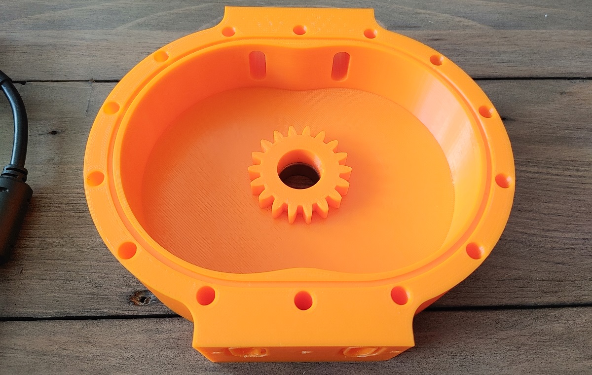
Here is the back of the current design which allows me to use a stock bearing for the drive shaft.
There are much larger notable changes to the front of the design. The housing now has inlet and exhaust ports, the direction of flow will determine the direction of the engine. The ports have an O-ring groove so I can attach some kind of a manifold, it's much better than gluing a pipe to it. The top of the housing will use an O-ring groove to seal it and a series of bolt holes to hold the end plate down. The end plate can be the back of another engine, but the very front housing will use a clear acrylic cover. I may use more acrylic plates between the housings if friction becomes an issue. Lastly the rotor has been modified so it can house a needle bearing which will not be used for the air engine.
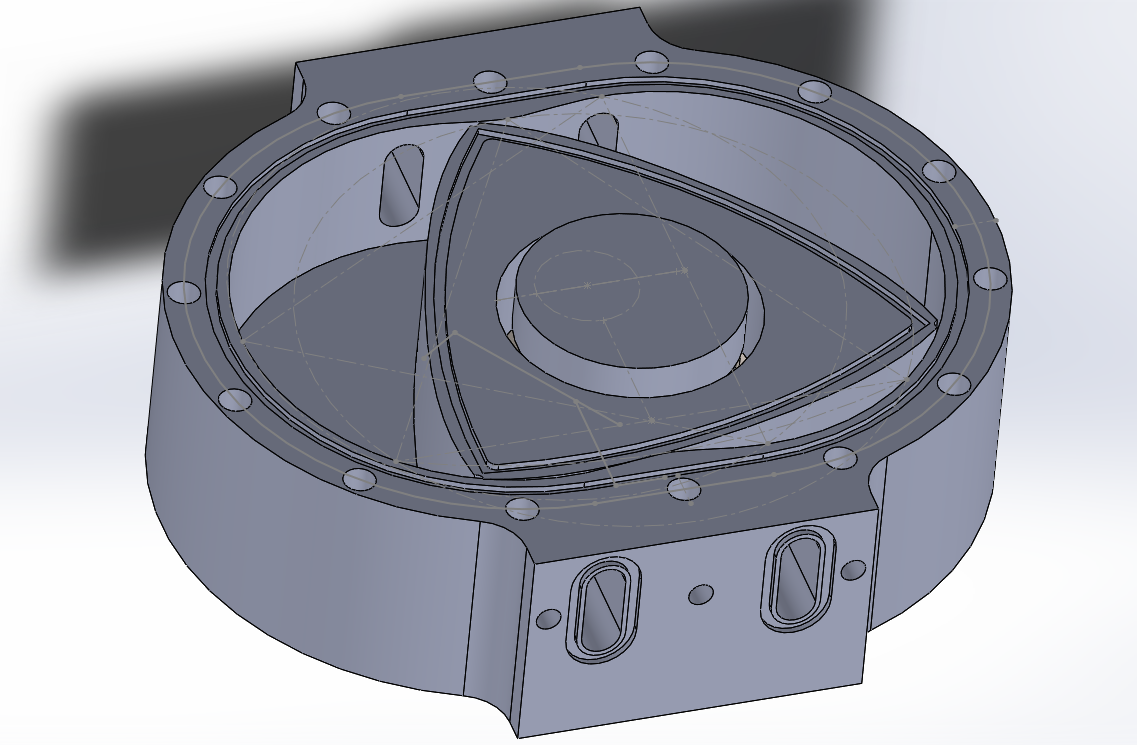
A single keyed shaft will pass through the centre of the engine which will also align the bearings. The shaft allows eccentrics to be pushed on in place but will also be free-floating, this allows assembly to be easy. I am happy with the design of the housing but not so with the rotor, especially the apex seal which I'm thinking of either gluing in place a rubber strip or O-ring cord.
The very first engine will need to be of at least two rotors in order for the drive shaft to assembly properly. However, "4-rotor" seems to be a bit of a keyword on the internet, so if I choose that as my first design then it is likely to do a lot better. Similarly the design after this will be a 6 rotor, hopefully I will have enough of a following to keep increasing the number of rotors.
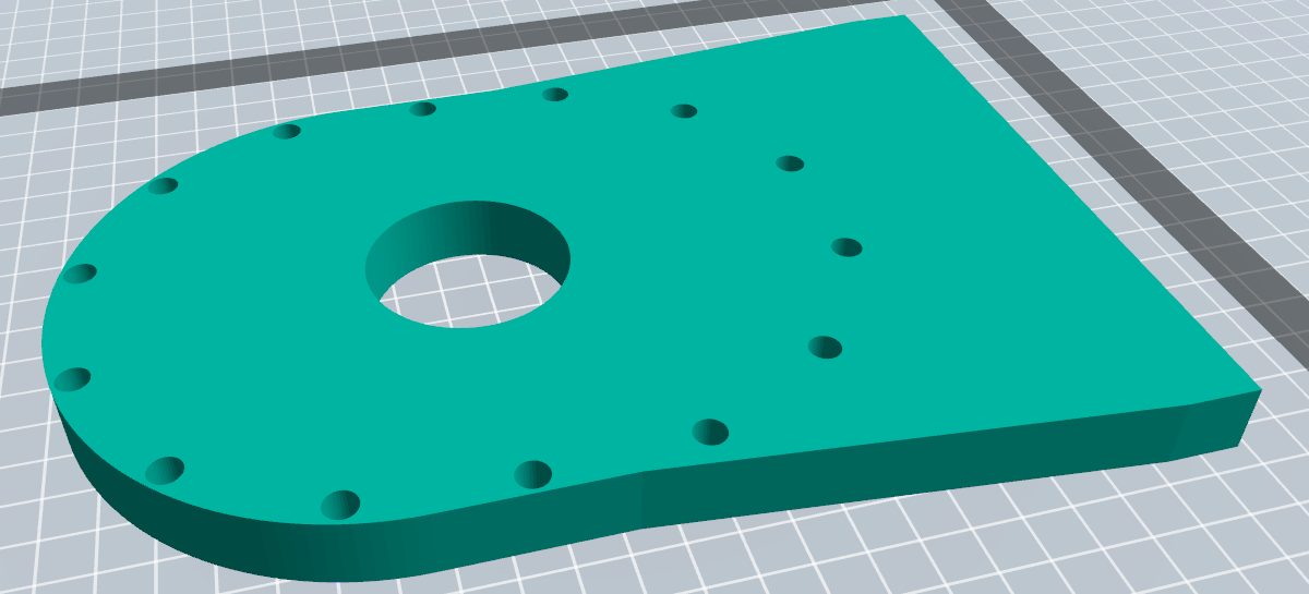
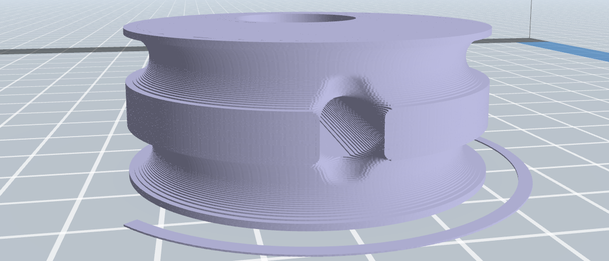
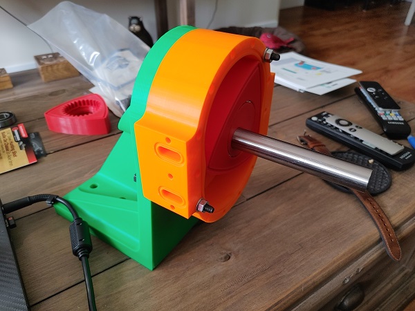
I did a lot of thinking while in the process of printing four of these housings, they take 19 hours each. I decided that the very first engine will be a single rotor until I'm happy that everything is dimensionally correct, in order to do this I also designed a mount. The engine mount needs to be sufficiently strong enough to hold a 6-rotor from just one side, a bigger engine will need a mount on both sides, but that's for later. In order for a single rotor to work I will need two bearings to support the drive shaft, one of these can be situated in the mount.
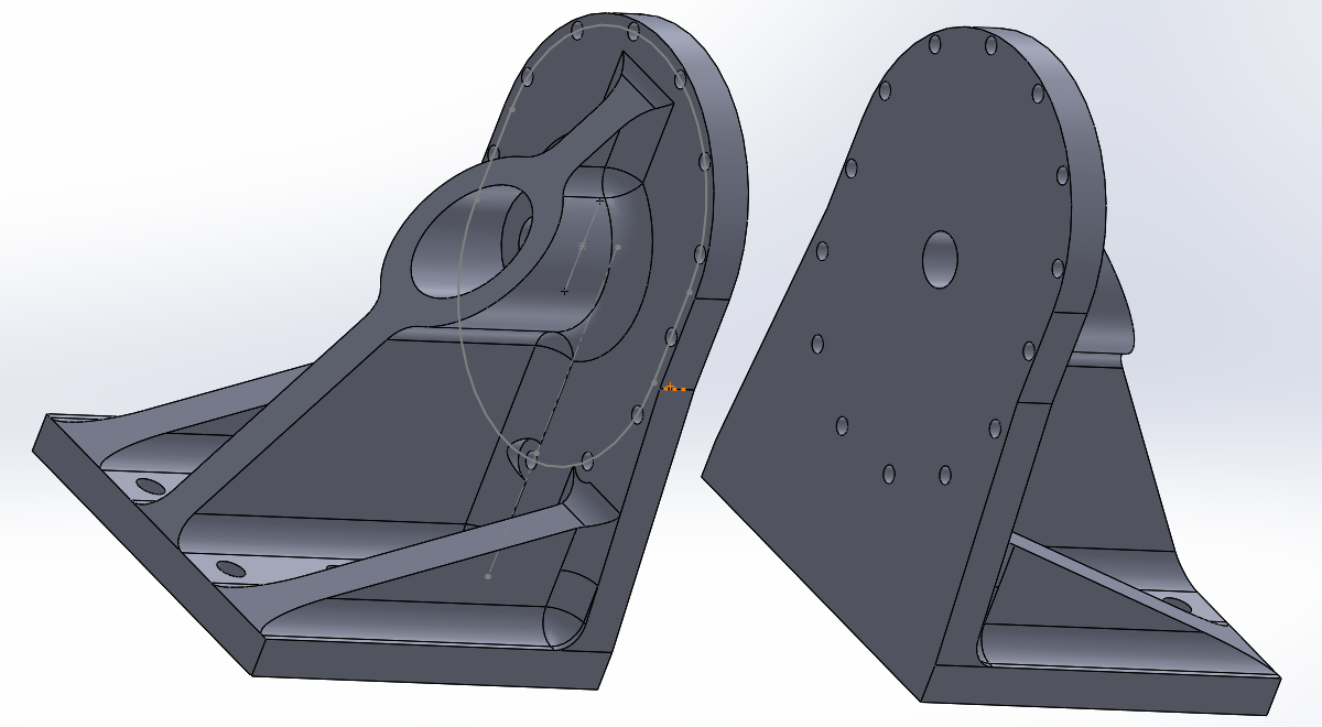
The mount will use about 400 grams of material with quite a low infill density.
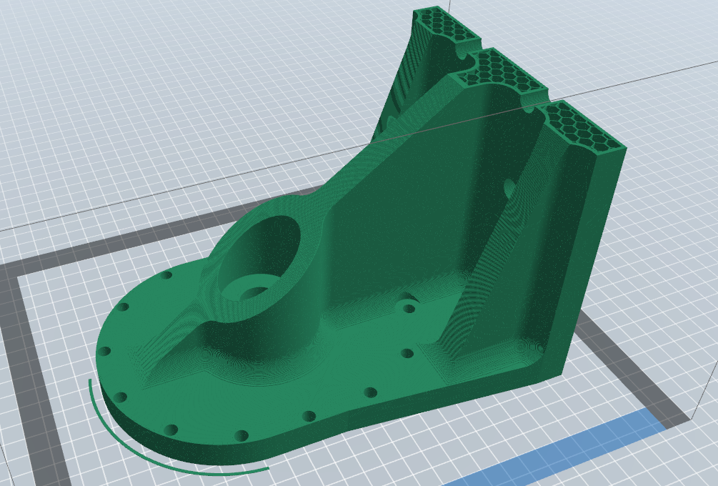
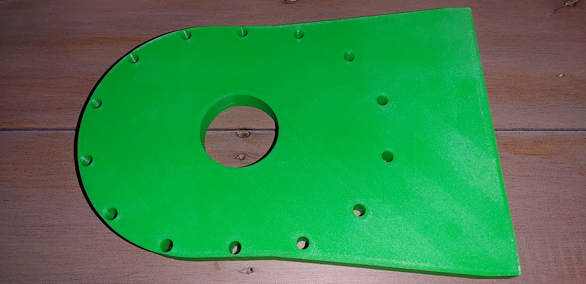
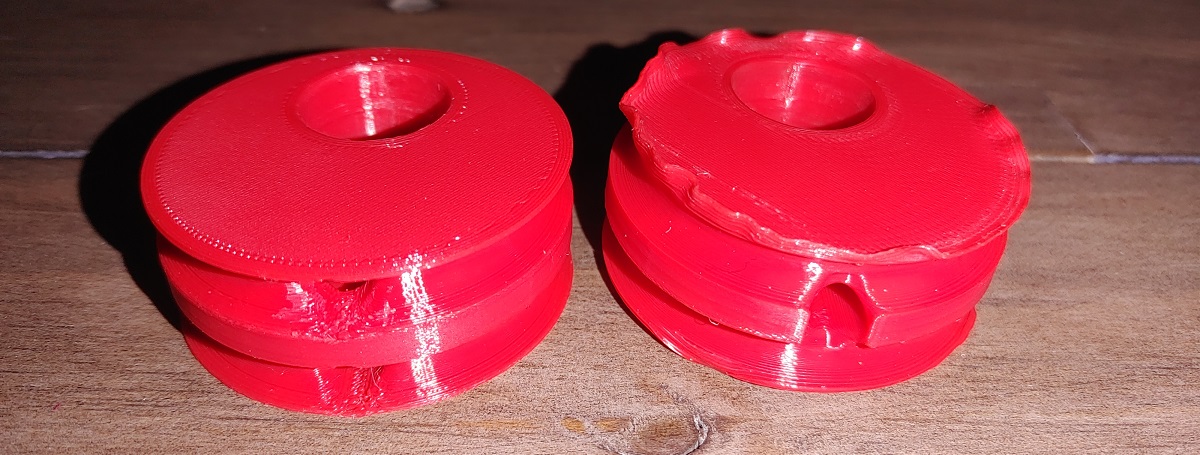
Here is the mount printed from ABS, I used pretty fast settings so it took 21 hours.
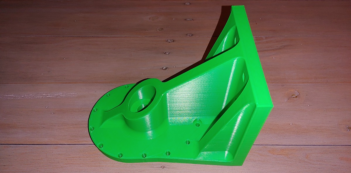
I plan on making this engine up to 24 rotors eventually which will require some intermediate mounts, that also means I don't necessarily have to bolt the engine down to something. Here is the modified design, basically the same without a foot.
This is quite a big part to print in ABS without it warping crazy, thankfully only a little bit.
Here is the design so far, note the additions of some port adapters. I will be gluing the air inlet pipes in place and letting the exhaust vent to atmosphere. I have not decided yet whether I will be using plastic on plastic for the rotor bearing or maybe incorporating something with loose ball bearings. The combustion engine will use needle roller bearings but those are a little too expensive for now.
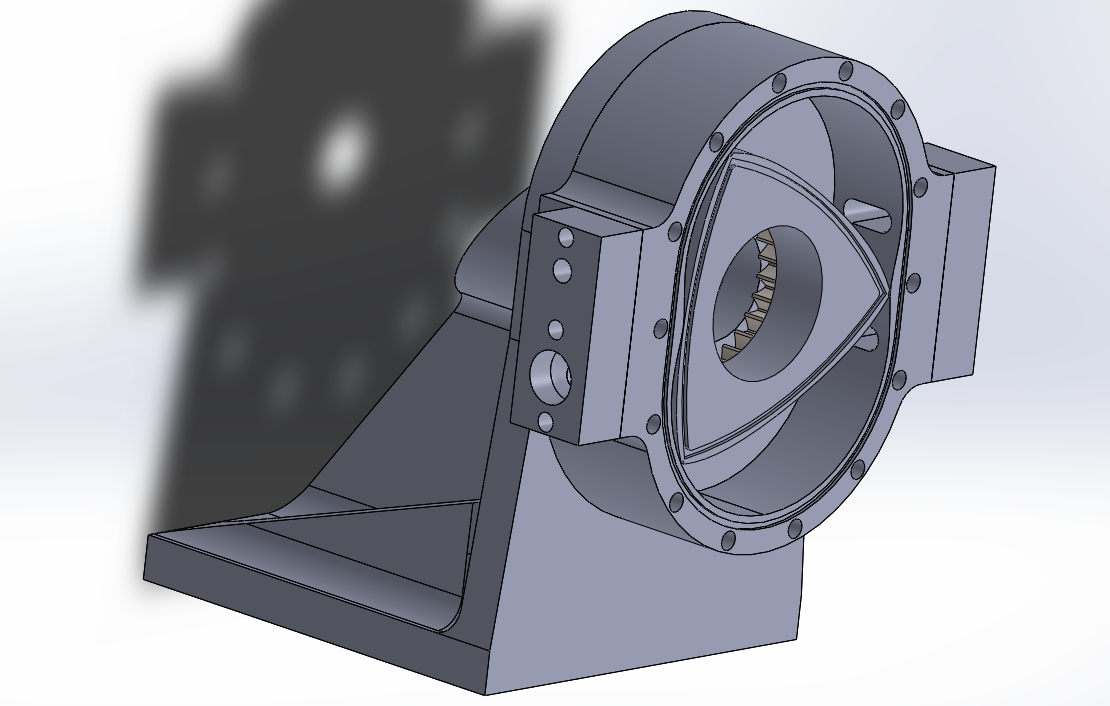
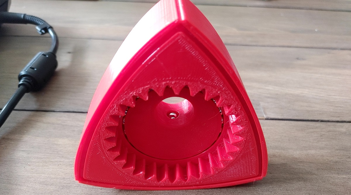
I have done the last modification needed for the design, I believe the engine is complete now. The combustion engine will use a needle roller bearing for the eccentric but these are fairly expensive. I was originally going to allow plastic on plastic but that's not such a great idea due to friction. Instead I have integrated some ball races, I will fill them with steel ball bearings. There is an access hole from the centre of the eccentric where the bearings can be inserted, once the drive shaft is in place the bearings cannot fall out.
I chose to print the housings in ABS due to the fact I have quite a number of reels, also because they have large flat areas. I will print the rotor in PETG since this sticks much firmer to the print bed, it is also very unlikely to warp. By having two quite different materials the meshing gears should last a lot longer. I don't expect a 3D printed engine to run for long, but I want it to be fairly good. I did some slight modifications to the apex seals to reduce friction.
The rotor came out really good, however it was not quite dimensionally correct. I also damaged this part as you will read later.
I also chose to print the eccentric in PETG for ease.
The eccentric... after I damaged it.

I picked up some ball bearings and assembled the rotor. I noticed a slight mistake I had made on the design of the eccentric which meant I could only insert a certain number of ball bearings. I also found the shaft to be too tight. I chose to heat the eccentric up with boiling water, this allowed me to insert the shaft but I damaged the rotor and eccentric in the process.
I chose to re-design the eccentric and print a new one. I adjusted the height dimension for the rotor and printed another one.
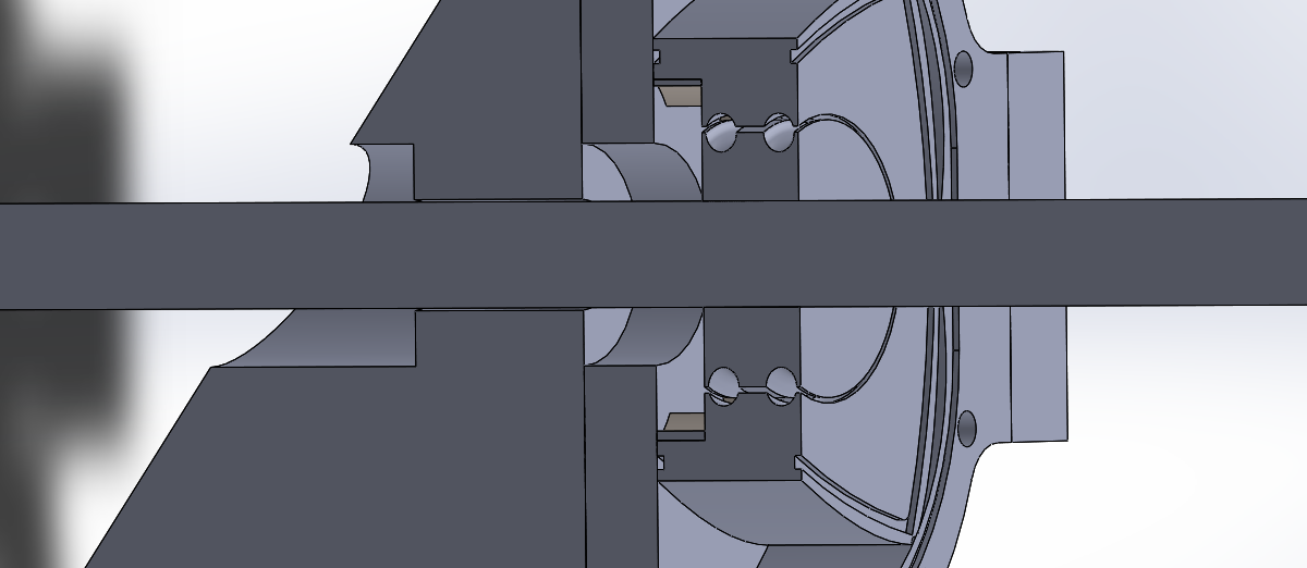
Here is how the eccentric is supposed to be assembled to the rotor, the bearings inserted from the middle of the inside.
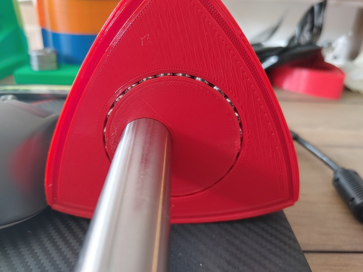
The shaft prevents the bearings from falling out. The rotor turns just as free as a bearing would without any slack.
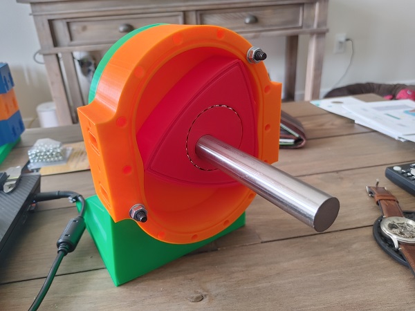
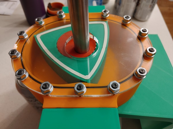
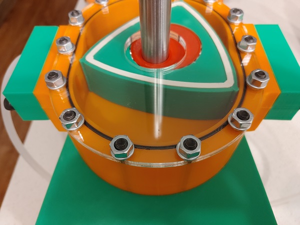
I also picked up some bolts and bearings to assemble the engine. Here is the housing in ABS, these came out really good.
The engine spins over perfectly.
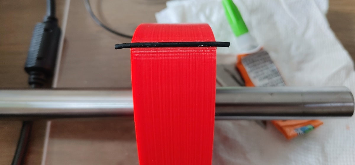
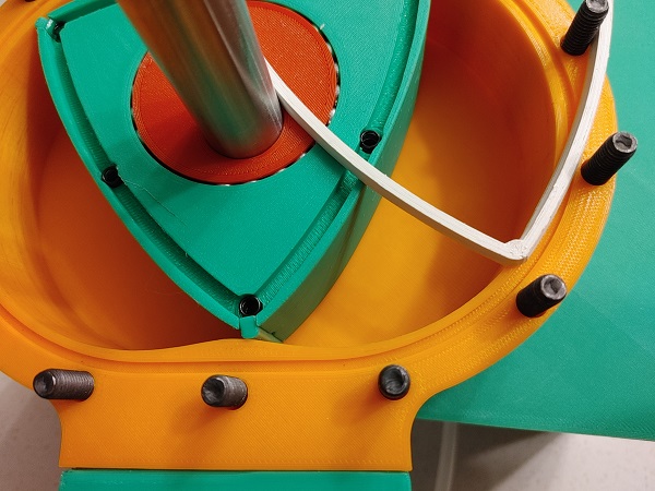
I chose to glue some O-ring cord in place for the apex seals, unfortunately they tore off when passing over the ports. I knew this could be a possibility, looks like I'll completely have to re-design this part of the rotor.
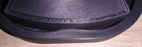
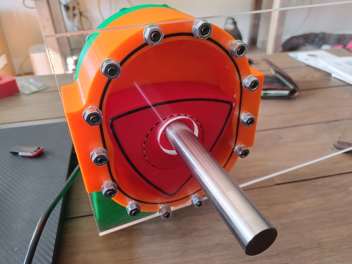
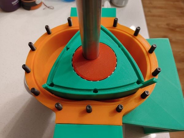
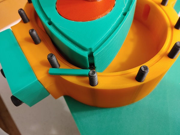
The original idea was that I could sandwich the back of one housing to the front of another. In practise this is exactly how the combustion engine will fit together, however that can be made to much tighter tolerances. With the 3D printed engine I will use a piece of acrylic sheet between each housing. The main reason is because this will be a much smoother surface and will reduce friction compared to the surface that stuck to the print bed. The very front housing is clear to make it more interesting when the engine is running.
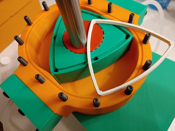
I chose to have these plates laser cut since 3D printed ones would not be clear, it also saves me a lot of time. Since I'm having to wait for some plates to be cut I mocked something up with a piece of acrylic sheet for a front cover. I got some O-rings to assemble the engine. I noticed the O-rings on the housing groove and the one in the top print side of the rotor stayed in place, due to the groove depths being correct. The O-ring in the underside of the rotor print needed a little glue, obviously the depth is not correct.
The engine is extremely stiff to turn over since there is too much compression on the O-rings, I knew this could be a possibility. I know the engine would run perfectly fine without any seals but there would be a lot of blow-by. The big reason I want the O-rings in place is to stop plastic on plastic contact.
I used the compressor I had to try and make the engine spin, it would not due to the amount of friction. I designed a new rotor which would hold a piece of rubber sheet for the apex seals.
The seals on the sides of the rotors had far too much friction to even move. In the end I removed all of the seals but still could not get it to spin due to the amount of air by-passing. I realised I need to re-think the design of the rotor in terms of the sealing. I need to make the seals much closer to what would be in a real engine. I also re-thought my original goal of making a 24 rotor 3D printed air engine, I simply would not be able to supply that amount of air, so 4 rotor is much more realistic.
I have to be fairly realistic with what a 3D printer can do in regards to detail. A real life working engine can have very slim and delicate seals because they can be made to a very tight tolerance. I have to consider that the seal is much softer and will roll if made too fine.
I 3D printed the rotor this time in PLA to save some time, it also prints a lot better than anything else. I made the apex seals in PLA to save some time and picked up some springs.
The side seals were printed in a single piece to save time, these from ASA.
The rotor would spin without placing the case on, but it would not spin freely. Once I put the cover on I could barely get it to spin at all by hand.
I realised that I had been spending far too much time on the seals without taking too much notice of the original design. It is the bearing that's the problem, quite simply when there is a load the balls compress into the plastic, locking the bearing completely. I have sent a number of enquiries out to get the required bearing, the one I will be using in the metal engine.
Note: Project is currently under construction, I'm updating every day or two.
Also, if you found this project interesting but you want to see an actual working combustion version of this engine then follow the link below.
24 Rotor Gasoline Wankel Rotary Engine - no link
Hello, if you have enjoyed reading this project, have taken an interest in another or want me to progress one further then please consider donating or even sponsoring a small amount every month, for more information on why you may like to help me out then follow the sponsor link to the left. Otherwise you can donate any amount with the link below, thank you!