Turbo Compressor Intake Flange
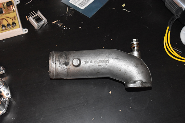
The car I'm currently driving has just recently had a turbo conversion, since the car was never intended to have one I had to make some custom parts, one of these being a flange. The compressor side of a turbo is what forces more air into the intake of a car engine to give it an increase in power, on the intake side of my turbo was a tube that originally bolted to it. Since the turbo was intended for a different car the tube that bolts in place cannot be used so instead I chose to machine myself one. The flange must fit the intake side and have a hose barb so that I can connect it to my air filter, since it is a small turbo I chose to go for 2 inch.
Design
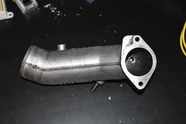
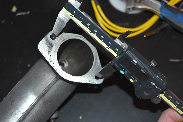
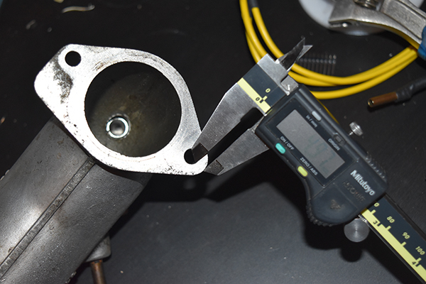
The first step is the design which is to take some measurements from the old tube, this is mainly the bolts patterns and the inside diameter. Here below is a picture of the tube.
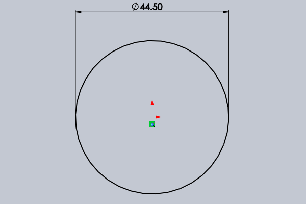
Since I will be machining this part it is always wise to make a CAD drawing, in fact it is almost vital when choosing to CNC the part. The issue I have with my current work CNC (I have permission to use) is that we do not use CAM and that all parts have to be manually programmed, not an issue but the process does take a little longer and also the code is not as efficient as it could be. The first step was to measure the easy parts so I started off with the inside diameter of the tube and made this the origin.
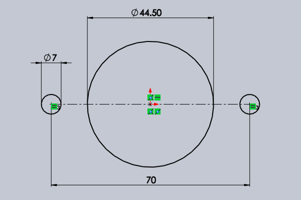
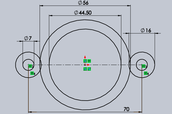
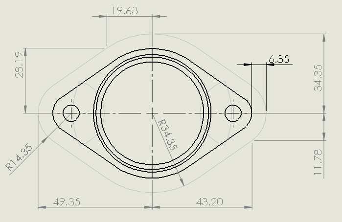
Next was to measure up the hole patterns, I can assume that the holes are inline with the bore, of course you should never assume but in this instance it was pretty obvious. I measured the most inner distance of the holes (63.0mm) and then added the hole diameter (7.0mm) to give me the distance centre to centre. I placed a construction line centered on it's midpoint at the origin at a length of 70mm, two circles were drawn at a diameter of 7.0mm (for a 6mm metric bolt).
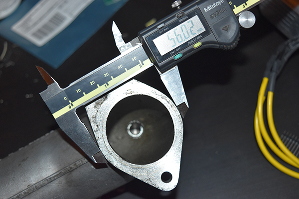
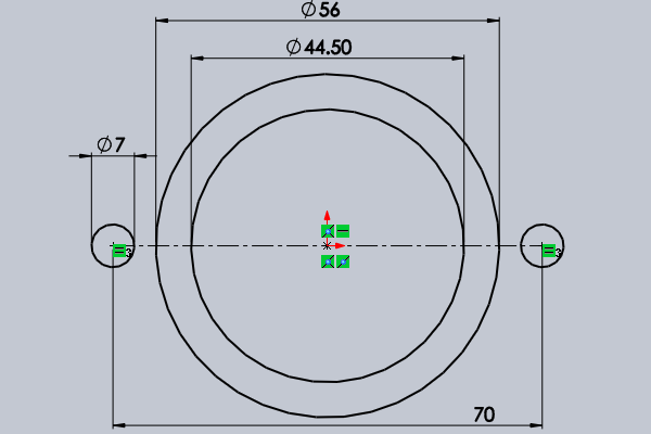
The easy parts have been measured so now it is time to work out some of the more harder parts, I do have access to a CMM (Coordinate measuring machine) but I prefer to do things will calipers and a little intuition. I chose to measure the major diameter of the of the centre circle, or how it appeared to be circular. This came out at 56 mm so I drew a circle at this diameter at the origin.
The outer radii of the bolt holes were also assumed to be circular. An easy way too find the diameter of this circle is to measure the cross-section between the outside and the inner bolt hole, this came out to be 5 mm. To find the radius you simply add this cross-section to half of the bolt hole diameter and then double it, this gives 17mm. I added two circles at 16mm centered around the bolt holes, why not 17? , well sometimes castings are not all that accurate and what I measured was a high spot.
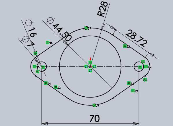
This is the part where I assume some more dimensions, I must think like the person who designed the original part and how they would have done it. Since they would have likely used a similar type of CAD platform I can assume some generalities. I drew four lines and placed them tangent on all of the circles, this ensures that all curves and lines on the outside contour of the part have a smooth transition, it wouldn't make sense to design this any other way so in reality it's educated guess work. I then cut away all of the lines that are not necessary, since a lot of the lines are lost I had to add in some more dimensions to fully define the sketch, these were as I found them.
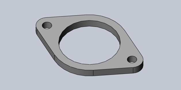
The part is then extruded to a depth of 6mm, this again is just a made up number since this part really bears little load. Making it too slim gives little room if I need to re-machine the part in the future and making the flange too long is just a waste of material.
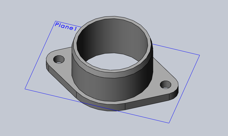
The pipe that will be pushing onto this flange fitting will have an internal bore of 2 inches or 50.8mm. I managed to get a 4" offcut of aluminium round bar at a length of 30mm for free, this is what I will use to make this part. Since I had such little material to play with it meant that I could only make the barb around 24mm, I also chose to keep it straight as it won't need much grip and it also makes some of the machining operations a little easier. The first step was to create a plane on the part, then a sketch and then the profile of the barb.
I inserted an axis and then revolved the sketch around it, I also added a 20 degree chamfer that will aid in pushing on the hose.
The solid part is now done but it is always a wise idea to make a drawing and print it out to work from. I never do anything official if it's for my own interest but I always make a drawing, the main reason in this instance is that I will be using the live tooling to mill a contour without tool radius compensation, this means that I have to draw a separate sketch outlining the milling cutter path, the cutter chosen is 12.7mm (0.5 inch).
Machining
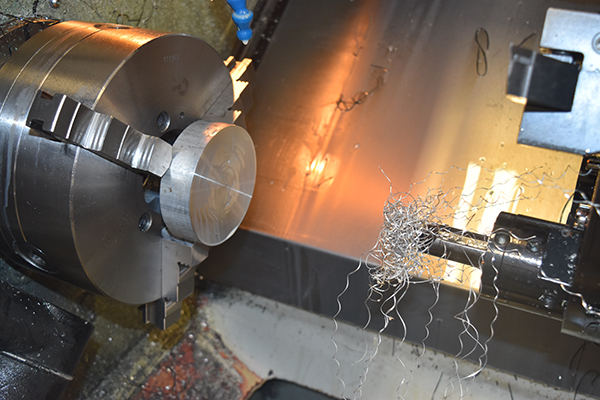
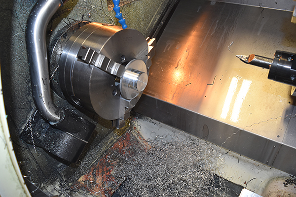
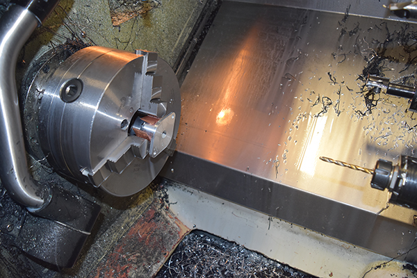
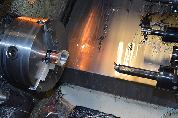
This part could quite easily be machined in one operation if it was to be from a longer piece of stock but since it's an offcut at a length of 30mm I must do it in two operations. There are of course many different ways in which you can machine a part depending on what capabilities your machine has, the machine I have access to is a Sinumerik C-axis lathe. The operations such as milling want to be reduced to a minimum since these take the longest, anything that can be turned should be to save time. You also want to machine all of the operations that require the most rigidity first leaving the final cuts to be shallow.
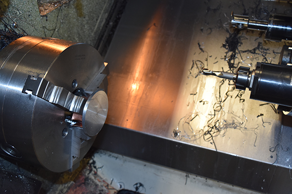
The piece of bar measures about 110mm and the major diameter of the part is 86mm, the first step is to reduce the stock down to around 87mm. I chose not to machine a groove on the barb simply because it would make the part difficult to hold later on. Since the barb is 24mm long I chose to hold onto just 5mm to leave around 25mm protruding from the jaws. I would then machine this down to the final diameter, that of the barb which is 50.8mm. Since I was holding onto just 5mm I chose to take 2mm cuts at a feed of 0.1mm/rev, I didn't have a chip breaker on my inserts either so there was the possibility of swarf, in fact I had to stop the machine many times.
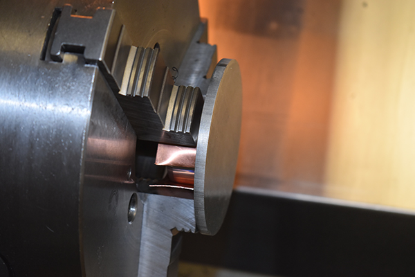
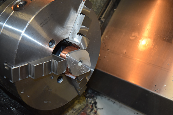
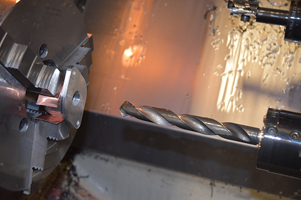
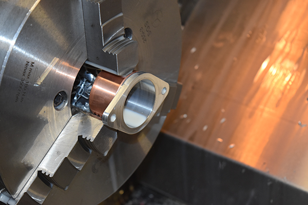
The part was then flipped around to machine the other side, this is the reason why I chose not to turn an indentation, I could have machined a split ring however to hold the part. I used a piece of copper as not to mark the part, other suitable options would be a cola can. I faced minimal amount of material in order to keep the part as long as possible.
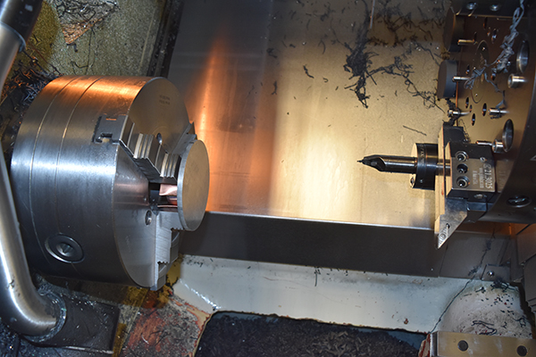
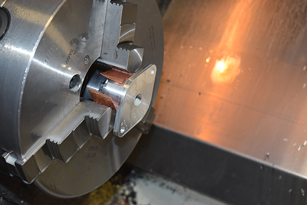
The outside was turned to 87mm since this would be a lot faster than milling, I then set the Z of the milling cutter.
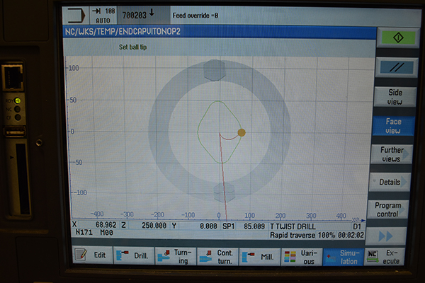
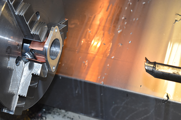
I don't have access to CAM software so I have to manually program everything, since this was just a single part I chose to do a lot of the machining in MDI mode (manual data input) because this is faster than writing out a program. I ran a simulation of the contour which looked to be ok, even though this is a single pass in the program I chose to offset the tool, it actually turned out to be a total of four passes, if I were machining multiple parts then I wouldn't cheat. I also used the milling cutter to drill out the center since it was a 2-flute.
The two bolt holes were drilled, this was a quick and easy program, I kept the same tool holder too but just swapped out the tool and reset the Z every time, since I was not using compensation for any of the operations it would not matter.
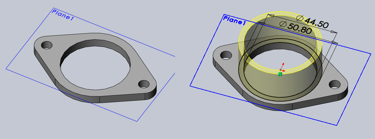
I drilled out the center to 19mm using MDI mode again. I placed a boring bar in the machine and used MDI again to bore out the hole.
The first pass took the diameter from 19 to 35mm, I had to since I didn't have smaller bar, I didn't have an issue and it turned real nice.
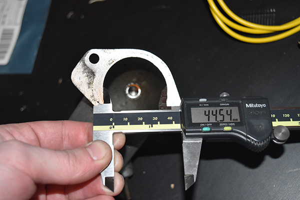
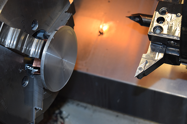
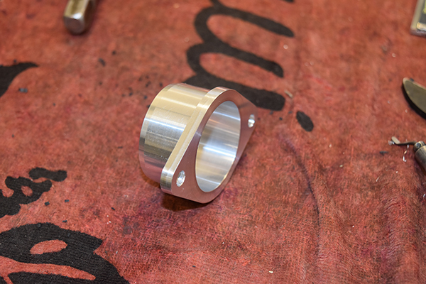
The bore was finished to the diameter of 44.5mm, the machining was finished. I quickly went around the edges of the part with de-burring tool, again if this was a production run I would have likely used a chamfer tool and programmed this in.
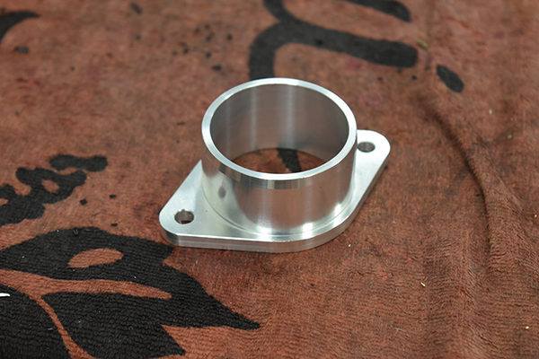
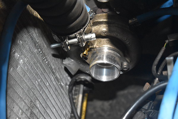
The part was complete and fit the turbo, if I have any trouble with the intake pipe staying on then I will likely throw it in the manual lathe and turn an indentation, I doubt I'll have any issue.
This is part of my Hyundai Tiburon turbo project, check it out!
Hello, if you have enjoyed reading this project, have taken an interest in another or want me to progress one further then please consider donating or even sponsoring a small amount every month, for more information on why you may like to help me out then follow the sponsor link to the left. Otherwise you can donate any amount with the link below, thank you!