Turbo Manifold Adapter
This is part of my Hyundai Tiburon turbo conversion project, the idea is to convert the car to turbo for as cheaply as possible. Normally when converting a car you need to have a custom turbo manifold made to suit the car and turbo which can cost thousands, there are also some cheaper poor quality ones for around $400 CAD which are prone to cracking. A stock turbo car will nearly always use a cast iron manifold just simply because they are robust, easier to make and quieter. The objective of this project is to make an adapter for between my stock manifold and my turbo.
Design
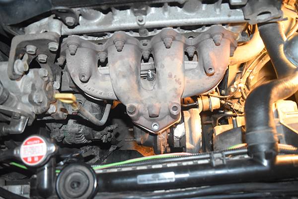
The first step was to measure the existing manifold of both the car and turbo mounting flange. I made some rough dimensions and came up with the design below.
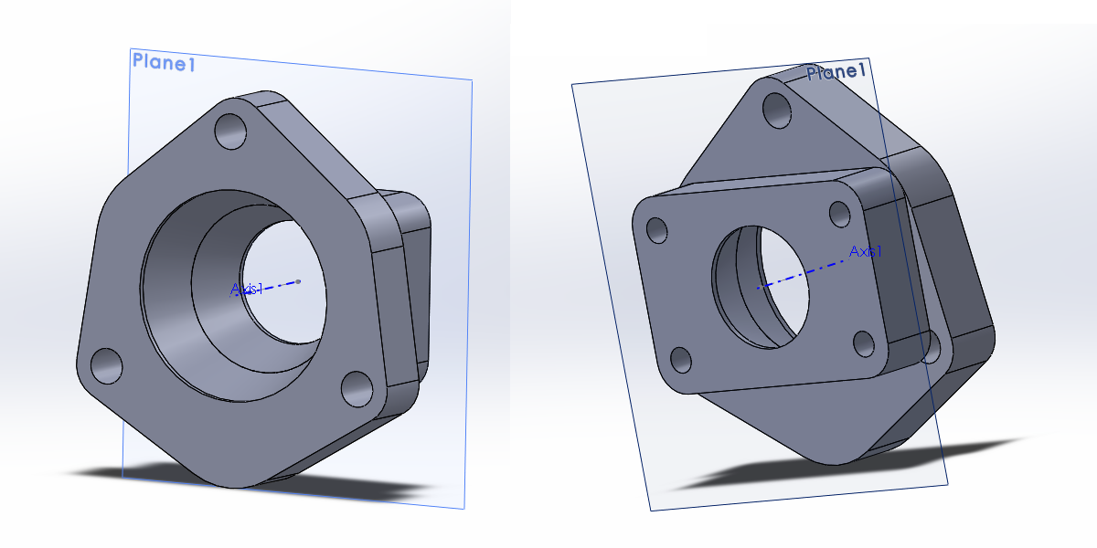
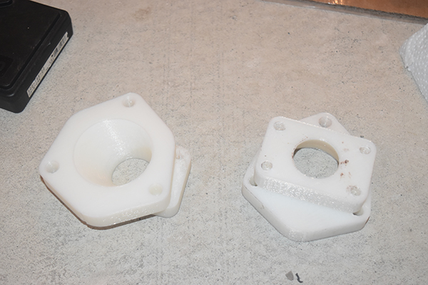
I chose to 3D print the part to see if the bolt holes aligned and whether there would be clearance in the engine bay for the turbo.
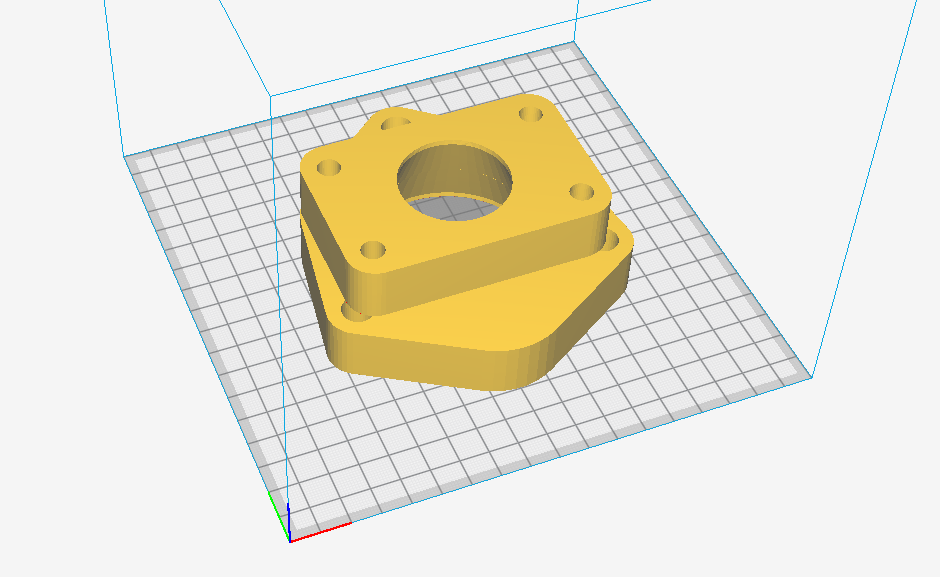
I had to offset one of the bolt holes slightly. The turbo was also very close to the alternator, too close for comfort. I chose to offset the hole, I'm not sure what you call it but a cone with a straight edge as can be seen in the design below.
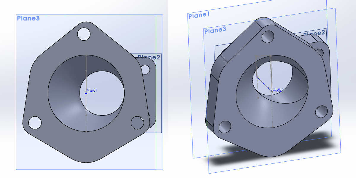
I 3D printed the part again.
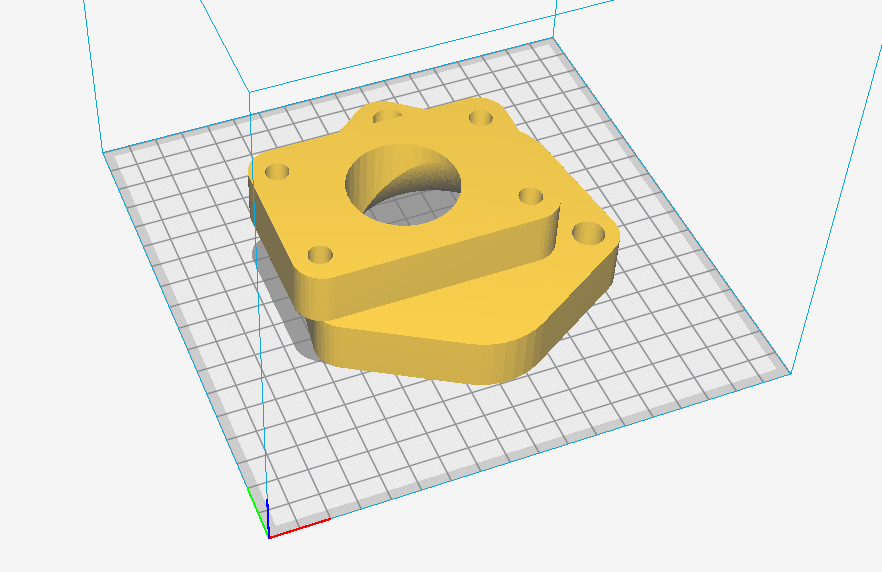
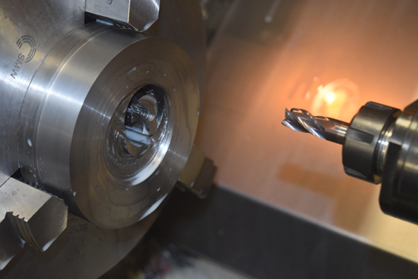
The adapter fit perfectly to the turbo.
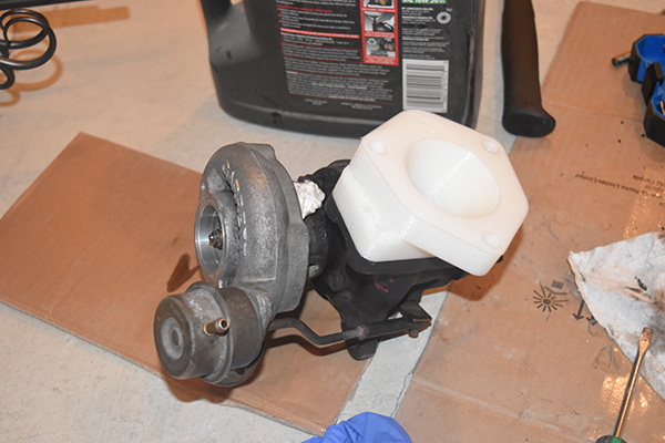
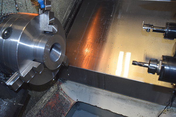
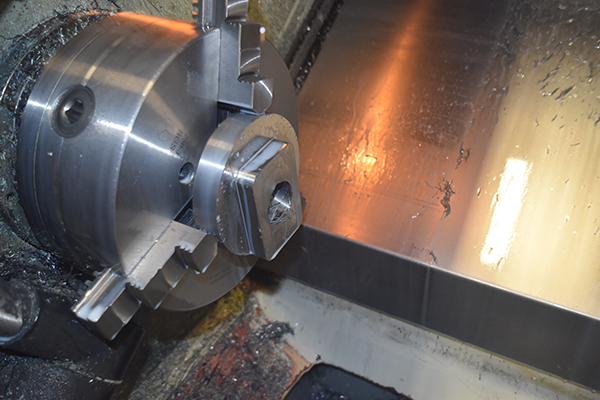
The turbo fit the manifold and there seemed to be enough clearance for the down pipe between the alternator. With that in mind I bought some 5" steel at a length of 40mm, it cost me $40 CAD ! , I should have searched around a bit more.
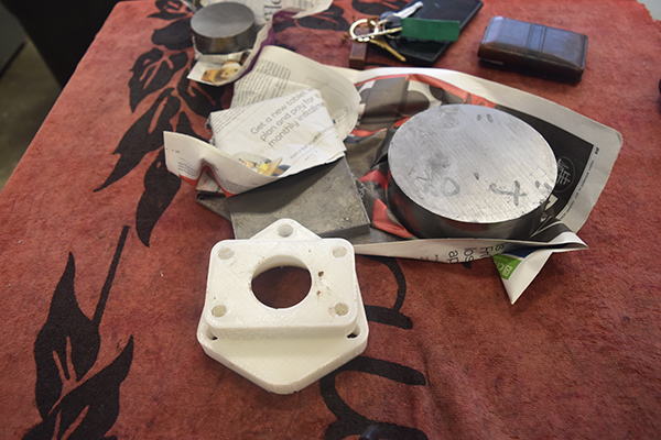
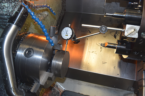
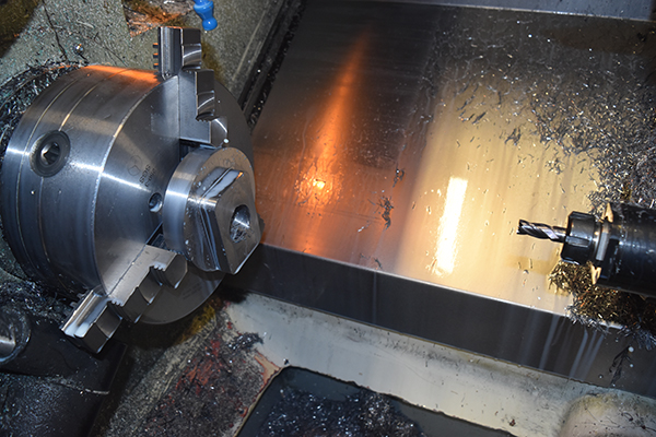
The piece of steel was clocked true and faced off. I machine plastic and I chose to use an aluminium insert, it was an old one but certainly not what I should be cutting steel with.

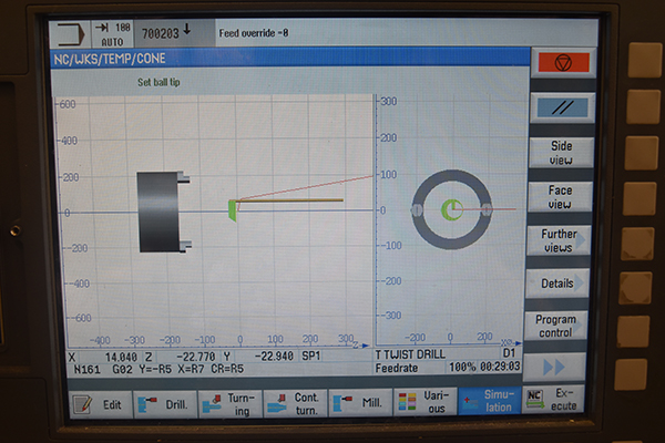
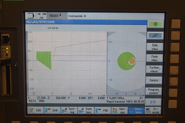
I wrote out a program to mill the cone, it worked on a series of variables that changed each time the program looped, this meant that I could keep to around 40 lines of code for the whole process, plus I don't have CAM software so it had to be programmed manually. Here is the machine simulation on the right, it takes a total of 82 passes, no compensation for the tool as it was an end mill.

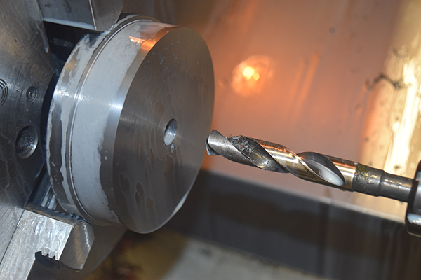
The cutter I had was an end mill so I chose to drill out the piece of stock first, I quickly realised a mistake afterwards that I should have drilled it to half an inch instead of 5/8", it wasn't a massive one since I could patch steel up with a welder if I had to. I first wrote the program for a 1/4" milling cutter to find it wouldn't touch the steel, so I rewrote it for a 5/8" milling cutter to find it lasted about a minute. The steel was supposed to be mild but I should have known with it having a bright finish that it was likely carbon steel.
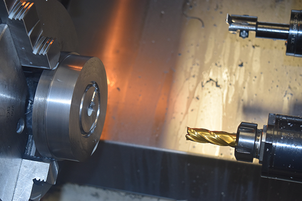
I chose to completely start from scratch again a day later and made the program rough the part out first in 5mm increments, it took a while to program but this would ensure my milling cutter would last. I also chose to go for a coated carbide milling cutter as these are far more durable and I can cut at a much higher speed.

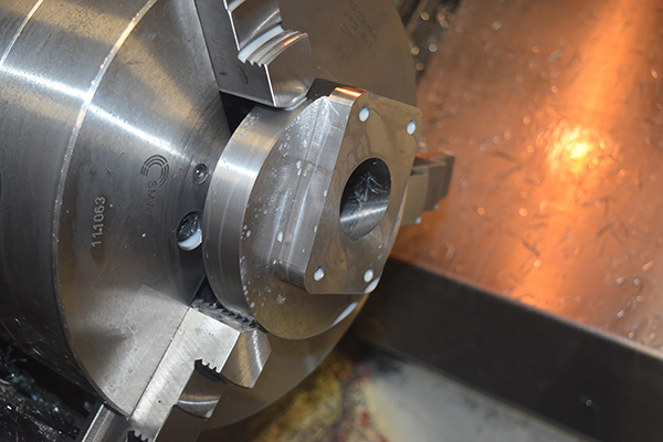
The cutter did a great job at roughing out the part, it then finished with around 80 passes to complete the cone. To be milling in a C-axis lathe is actually quite troublesome since there is not a lot of rigidity in the system, the machine handled it pretty well.

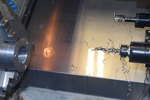
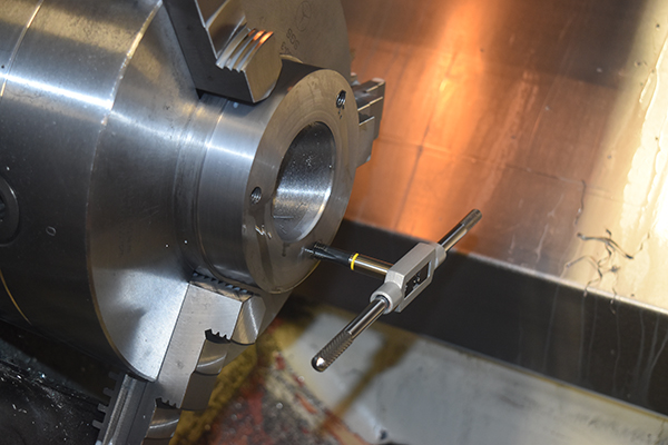
I then wrote a piece of code to drill out the holes for the three studs that will bolt this adapter to my manifold.
I didn't want to risk breaking a tap so I chose to do it by hand in this instance.
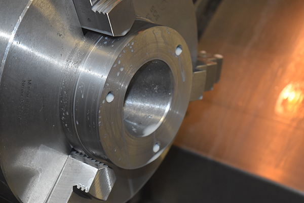
If you look carefully at the cone you can see where the drill bit at the very beginning bit into the cone, it's not an issue and could be patched up if this was a production run. I would have also doubled the number of passes and used an end mill with radii on the corners (bull nose cutter) to improve the finish. I will probably just leave it the way it is because a rough finish can sometimes allow more flow due to air being trapped in the grooves and the over lying air passing over has less friction than if it was passing against smooth bore steel, this is just a theory. I flipped the part to machine the flange for the turbo side, this was quite a long program because I didn't use CAM software. I chose to use a series of variables to cut the part, this reduced programming time but also increased run time, since it was a one off I still saved time.
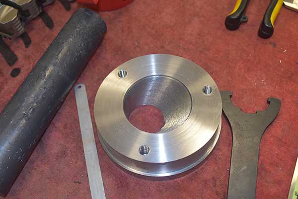
The stud holes were drilled and tapped.
The adapter fit the turbo and the existing manifold.
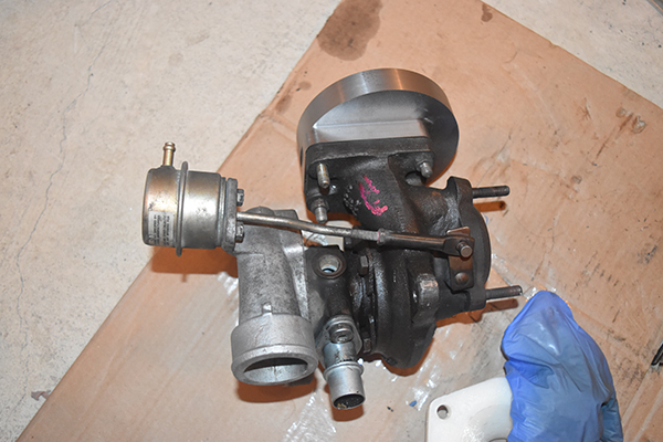
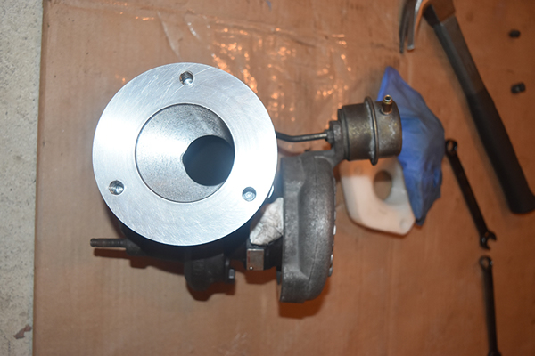
This project cost me about $100 CAD for materials and tools which is far cheaper than even the poor quality manifolds. The great thing with doing it this way is I can easily pick up a manifold from the scrap yard if it cracks and this adapter is bright steel which is far less prone to rotting.
Hello, if you have enjoyed reading this project, have taken an interest in another or want me to progress one further then please consider donating or even sponsoring a small amount every month, for more information on why you may like to help me out then follow the sponsor link to the left. Otherwise you can donate any amount with the link below, thank you!