ECU 1 - Modular Prototype
Engine Control Unit. For a long time I have been thinking about developing my own standalone ECU since all of the others out there are very expensive. A while back I converted a motorcycle from carb to EFI, the project worked in the end but I realised that I needed to be more competent with programming microcontrollers, I now think that I am.
My current platform for this project is a 1998 Hyundai Tiburon which is also my daily driver (Aug 2018). In basics the car is a twin cam, 2.0L naturally aspirated engine. I have recently converted the car to turbo while adding a secondary set of injectors. The car runs on the standard ECU in which it controls stock timing and the stock injectors. I have built my own fuel controller that calculates how much fuel it needs to add on the secondary rail when I hit boost. The issue is that my fuel controller has to do this calculation on the previous combustion cycle meaning that it cannot run accurately. The largest issue with the whole system is that the stock ECU is programmed for the worst grade fuel whereas I'm using 102 RON, 94 Octane fuel. The stock ECU pulls timing to avoid knock, and hence a loss in power.
I have gone through many ECU designs in the past, check out the project graveyard. I have realised that for what I require a modular ECU will be the way to go. The idea is that the master can be the same, all it does is process signals. Then, depending on the application the user can choose what extra modules they need. So on the input side there will be the basic module that reads MAP, MAP, TPS and IAT. There will be additional slots for oxygen sensor modules, VVTI, temperature, etc... Similarly there will be different output modules such as ignition, injection, axillaries, boost controller. This all means that I would not require a whole new ecu if I decided to add an additional fuel rail, simply I add an extra module or replace the module from a 4 injector to 8. A modular system is an excellent choice for someone who likes to continually upgrade their car. The idea is that when I get this ECU working and arrive at my final version I will be at the position where I can start doing my own low budget car builds, part of a side-line entertainment project.
I will also add that some of this page may also be a little cryptic, it makes sense to me, it is also a reference to when I wire and program the modules.
The first prototype will hopefully do the following,
* Take inputs from all the common sensor types
* Control up to 4 independent injectors
* Control up to 2 coil packs
* Auxiliary functions such as fuel pump, boost, purge valves, etc...
Most of the modern ECU's run a single processor, currently they are 32-bit at a speed around 60MHz. The thing is that an engine is analogue and is very slow compared a microcontroller, there is nothing more a 32-bit computer can do compared to an 8-bit microcontroller which is what I will use for this project, I may migrate to 16-bit in the future.
The thing with a microcontroller is that it can only do one task at a time, running multiple tasks is known as multiplexing in which the processes are all shared reducing the speed of each individual process, again not much of an issue for something running this fast. To fit all of these processes into a single microcontroller is quite a task, the main issue is that some processes are delayed because the core is dealing with something else first, in all it's difficult to optimise a program of such scale.
The difference with my ECU is that there will be a microcontroller dealing with each specific module, this means that it will concentrate on it's specific task and will not be burdened. It is common for performance car builds to utilise multiple control modules instead of a single computer, it minimises the risk of faults or errors and makes it easier to fix if these arise.
So I will have a microcontroller for each of these modules.
* Sensor Decoder Module
* Fuel Control Module
* Ignition Control Module
* Main Programming / Fault Module
* Auxiliary Module
I was originally going to integrate the input module in with the main control module since every car will require a MAF / MAP, TPS and IAT sensor. I then got thinking about some cars that utilise two of these sensors for each side of the engine. It would make more sense to keep them separate. A cheap basic module for single sensors and then an upgrade option for multiple sensors. All of the other modules can change depending on what kind of outputs they need to control, this makes room for expansion later on. So the first module I will build is that for the sensors and the programming module. The master module will however contain inputs for the CAM positions sensor and the Crank position sensor.
So this system will all have to link together in a specific way and I must also have some kind of a storage system for the maps.
All of the modules will be linked via an SPI bus, a separate bus for the input and outputs modules. The master control module will individually select the input modules in order to retrieve the data and then organise it. This data is then sent out to all of the output modules, they all read the data at the same time and simply ignore the data not required.
The first thing to do would be to list all of the sensors required to run an engine, this does not included sensors that may help.
* Cam Position
* Crank Position
* MAF - Mass Air Flow
* MAP - Manifold Air Pressure
* IAT - Intake Air Temperature
* TPS - Throttle Position Sensor
Most of these sensors either provide an analogue signal, digital or a resistive load. Sensors such as these do not require any pre-processing but two that do is the knock sensor and the crank position sensor.
Cam Position Sensor - This sensor is used to determine which cycle the cams are at. The purpose is almost exclusively for fueling purposes as to inject fuel into the correct cylinder on the intake stroke. Some cars do have a coil per cylinder too so it can also be used to determine when a coil should fire. The sensor is most commonly a hall-effect sensor which provides a digital output of when a metal tooth passes it. Since the sensor is digital it is not particularly fast nor accurate, it is not used for accurate timing and only a position reference.
Crank Position Sensor - This sensor is used to determine the position of the crankshaft and is needed for ignition and injection timing. Nearly all sensors are of what is know as the variable reluctance type, it is basically a coil and magnet, when a toothed gear passes over the sensor a voltage is produced. The voltage produced is very similar to a sine wave in that it is alternating, when the tooth passes at the middle of the sensor the voltage crosses polarity, a zero crossing detector is used to determine when this happens. The microcontoller can then work out the position of the crank with regard to how many teeth have passed, there will be a position on the timing gear where a tooth or a couple of teeth are missing, the computer knows this space is before TDC, it all depends how the timing gear is setup to which tooth is TDC (Top dead centre), I will work this out later.
MAF Sensor - Mass air flow sensor does exactly what it says. The ECU knows how much fuel needs to be added for the right combustion conditions. The most common sensor works via a hot filament, as air passes over it gets cooled, it needs extra current in order to regulate temperature. The current is converted to an analogue voltage to represent the mass of air passing. The great thing with this particular sensor is it measures mass and therefore it does not matter what altitude, temperature or pressure the sensor works at. Even though the sensor is very accurate it is often placed quite a distance from the engine, it makes tuning very difficult due to the delay in response.
MAP Sensor - Manifold absolute pressure sensor measures the pressure as close to the intake as possible. The ECU calculates the fuel required for combustion by engine speed, volumetric efficiency, temperature and manifold pressure. The MAP sensor utilises what is known as "speed density" to calculate the correct amount of fuel. This method can be fairly accurate with a good tune but it takes a lot of testing to get an accurate one. The great thing is that the sensor is very close to the valves and so provides a very fast response. Since the sensor is fast it makes tuning actually fairly easy for most applications, it is often the most common go-to on aftermarket applications.
IAT Sensor - Intake air temperature sensor is used to help determine the density of the incoming air. An IAT is only required on the fueling side for an engine that uses a MAP sensor, it is a very vital component in determining air density. The issue with the sensor is that it's hard to know where to place it, too close to the engine and you may get false readings due to heat soak, likewise too far away the temperature entering the engine itself will be inaccurate. The IAT sensor is mainly used for the ignition side, the hotter the air the more chance there is of knock. The ECU reads the temperature in order to fire at the optimal time, a high advance results in more efficiency but it risks knock which can be fatal to an engine.
TPS Sensor - The throttle position sensor is for the ECU to know what conditions to run the engine at, or more accurately the air to fuel ratio. If the throttle is barely open then the car is running at a low power, combustion can be leaner and therefore more efficient. If the throttle is fully open then clearly the engine is running at high power, it choose a rich mixture as to provide the most power.
Timing Module
The main control module will have a total of three inputs, one of those for CAM and the other two for Crank / CAM. The reason to do it this particular way is that it makes room for a variable reluctance sensor board, commonly that will be just the crank but sometimes it will be CAM. This section is dedicated to that timing module, the reason to keep it separate is because simply it may depend on what sensor is being used, whether it is VR, light or hall effect. For my particular car the CAM sensor is hall which means that it can use the separate input on the main control module. The timing module for my car will be for the VR crank sensor, it will also be a dual module due to the chip I selected.
There are quite a few ways in which I could deal with a variable reluctance sensor. The sensor is basically a coil with an iron shaft running through it, the shaft is perpendicular to the timing teeth on the crank. As teeth pass the coil it produces a sinusoidal waveform, in fact as the tooth passes the middle of the coil it is the point where voltage crosses from negative to positive (it can be the other way around if polarity is swapped, this is very uncommon). It is known as a zero-volt crossing and the hardware used to detect this is called a zero-crossing detector.
The largest issue is that there will always be some noise present and this could cause a zero-volt crossing when simply there is not one. There are many ways of incorporating some kind of hysterisis into the device to combat noise. There are three main chips manufactured specifically for the use with VR sensors, these should always be considered as they may give the best chance. Out of the three options I found the one that came in the best package, the easiest layout and the cheapest. The chip I chose ticked all of these boxes, it is the NCV1124 which also has two inputs.
The circuit is very simple, here is the diagram taken from the datasheet.
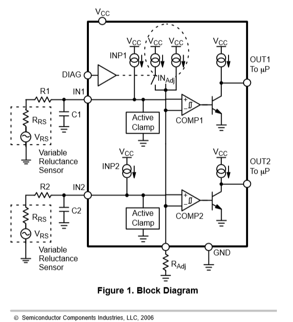
A lot of VR sensors are very similar in construction so thankfully it makes the choice of components relatively universal.
Something to take note of is the sensor is basically a generator, the faster it turns, the more voltage is produced. It can be quite common to see hundreds of volts produced, normally the circuit is designed for 250V peak.
A very important design consideration are the resistors R1 and R2 since these limit the current to the chip, these can in fact dissipate a large amount of heat.
The application note places the resistors R1 and R2 at 22k ohm, this results in 11mA peak and around 3 watts in heat, hefty resistors are required.
There is an application note as to what the components values should be, I chose 22k ohm for R1 and R2, and 22nF for C1 and C2.
The resistor to determine the crossing threshold was set at 24k ohm.
All of these components are pretty much the standard values to be chosen for this particular chip
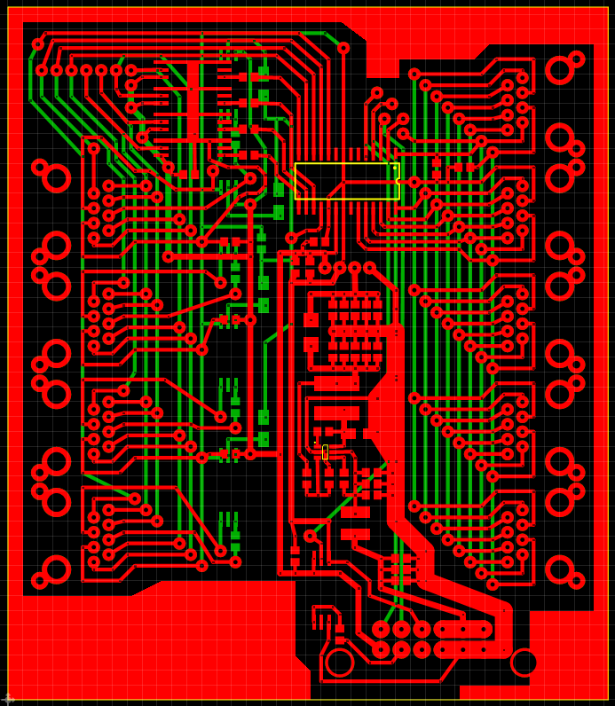
The next step was to create a circuit board. Each and every board will be isolated as to avoid noise and grounding loops, a problem I have encountered before. Since the board has to be isolated it means that it will require a dedicated voltage regulator, for this I have chosen a buck type converter. The reason as to use this type of converter instead of a linear voltage regulator is because it is way more efficient and does not have to dissipate a lot of heat. All of the outputs from the board are isolated via opto electronics.
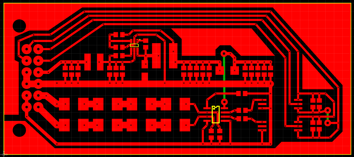
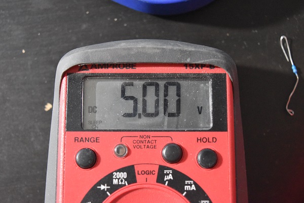
Since there were only two traces on the opposite side of the board I chose to go single layer. Since this was the first board I had done using this design of buck converter I thought I should test it.
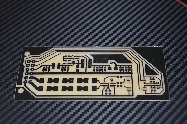
I went with all the same value components as the application notes, the regulation resistors chosen to a 1% tolerance. As you can see it is perfect, really happy with this chip. The one thing I did slightly different was to use multiples of capacitors for the filters instead of just a large one, why, simply it worked out a hell of a lot cheaper.
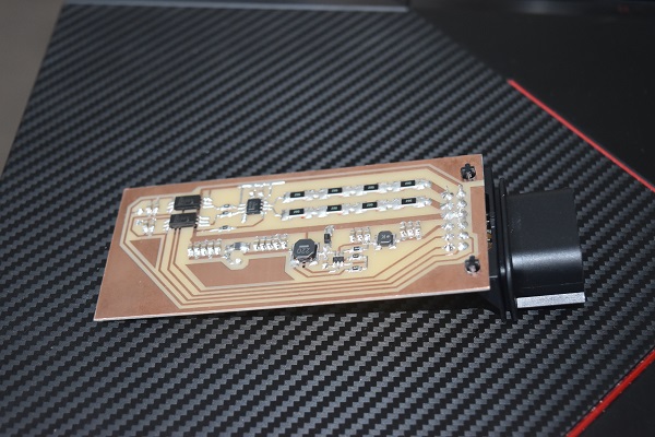
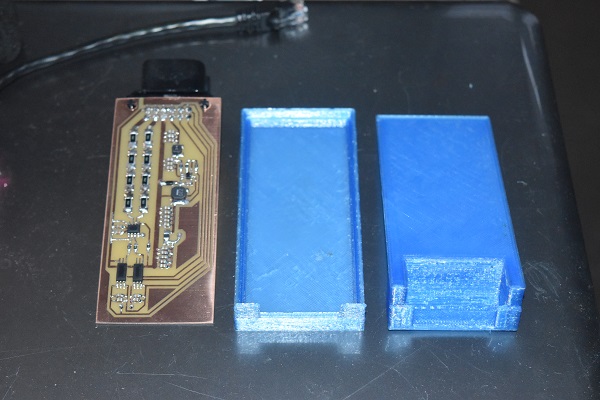
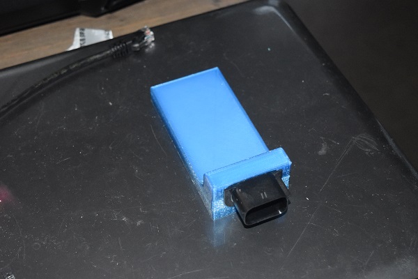
Since the board is intended for automotive applications and will be exposed to moisture I chose to seal it. I used something called conformal coating which I believe is acrylic, it stops corrosion, static and also noise. I intend for all the boards to be housed in metal casings, but for now I chose to 3D print one in polycarbonate.
For my own personal reasons I have chosen to create a pin diagram, it just makes things easier it being online.
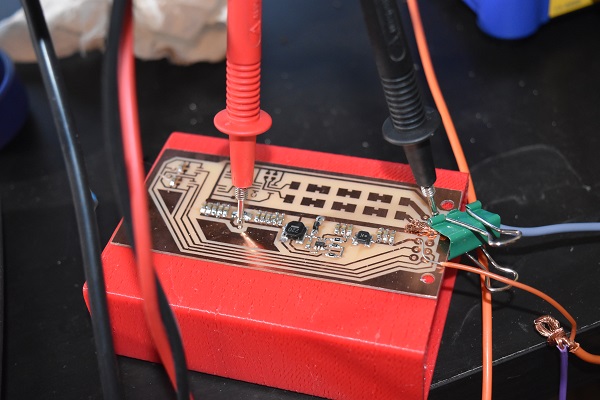
This is proof on the above board working. The input is connected to a VR sensor and the segmented wheel turned slowly by hand infront of it. This test shows that even when the timing wheel is turning very slowly and the voltage signal from the sensor is very small that this chip is incredibly sensitive.

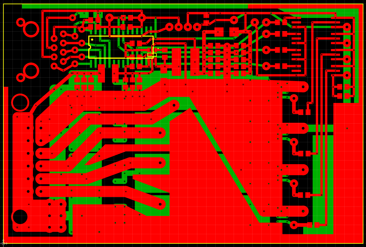
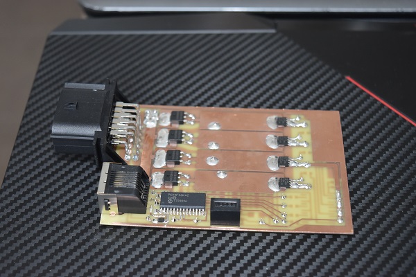
Control Module
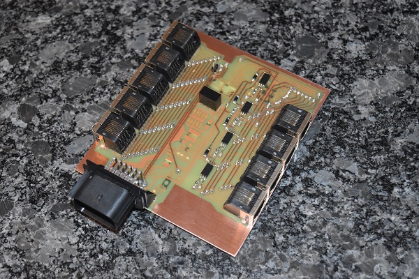
This will be the brains of the system, it is what sorts the data. The idea is that it will be able to select each of the input modules in turn to retrieve the desired information from it. It will then output the data via a single bus to all of the output modules. After doing some design on the board I decided that I should limit the board to four input modules and five output modules. All modules will be optically isolated from each other, this helps to reduce noise and keep the system accurate.
All of the input modules will be isolated from the main control modules.
The output modules will not be isolated, it is actually their outputs which are isolated themselves.
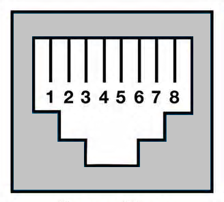
I chose to go with RJ45 connectors since these are pretty cheap and ready made. I'm not particularly sure how suitable they are for automotive applications but I can upgrade in the future.
This board again has it's own separate supply, a buck converter again. It also utilises a DC to DC converter to isolate the main brain, 5V to 5V.
I really do not like to place many mechanical components as these are subject to failure, one of these is a jumper, but at least this can be cleaned or replaced if necessary. The jumper is there because I have designed it so that the main microcontroller can be programmed through the RJ45 connector. The chip has to be reset via high voltage, that pin is only an input too, the jumper is there for normal operation as it bridges to an output pin. The high voltage reset could possible damage the chip or not allow a reset for programming, hence the jumper.
I have often placed an ISCP header on all of my boards for programming, by using the RJ45 port it cuts down on complicated board designs.
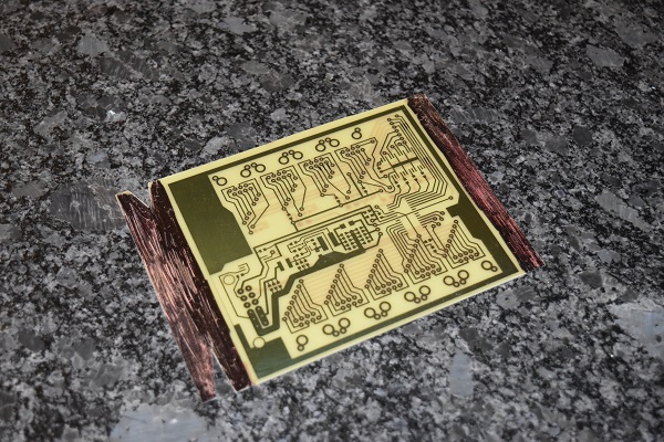
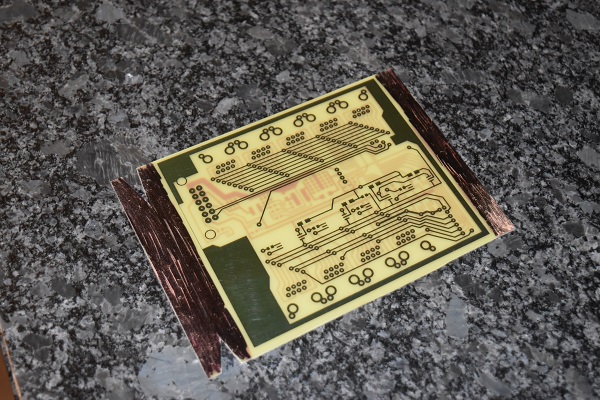
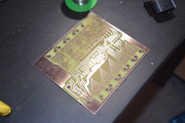
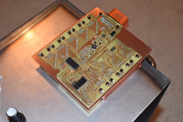
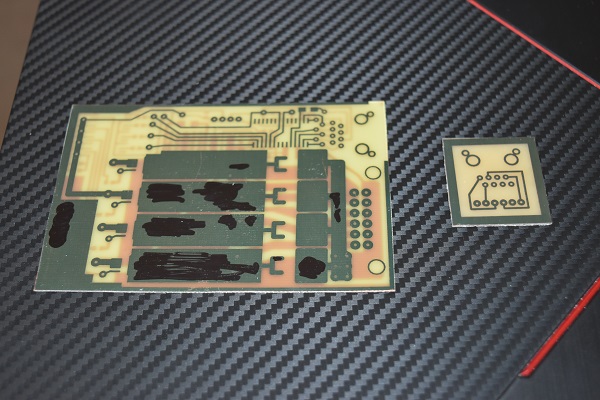
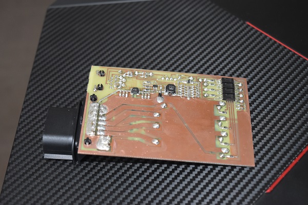
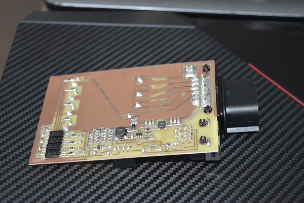
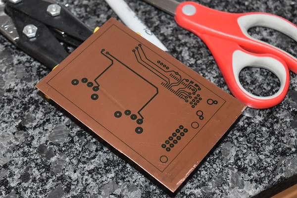
The board after etching. I used to try to save every last bit of board as I could, all it does is make it difficult to handle. The one thing I always like to do is colour in all of the wasted copper with a marker pen, this saves the life of my etching solution.
Since the board was of the fibre kind it meant that I could trim it down with some tin snips without issue. The one part I really dislike about making boards is the drilling part since it's so tedious, it was well worth migrating to surface mount. I inserted all of the connectors and the through hole pins, it is so much easier using headers instead of bare copper wire.
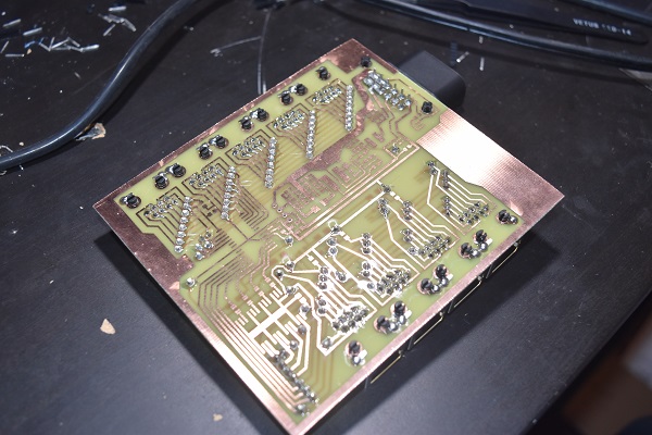
The board is actually very simple, it didn't take a huge amount of time to solder all of the components on. One thing I'm finding really random is the quality of the boards, they are from a very reputable manufacturer too. I find that the developing time varies hugely between boards. Another thing I notice a lot is scratches through the photo-resist, I think this could just be down to handling. It all means that I have to closely inspect all of the traces for breaks, not a major issue.
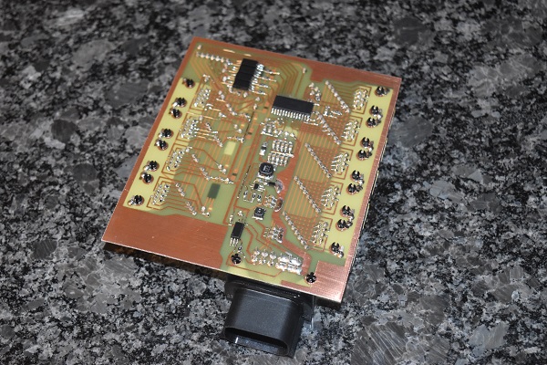
I gave the board a very thorough clean in solvent to remove all of the flux. I taped all of the connectors up as these cannot be sealed. The RJ45's are gold plated so will not corrode, the other connector is sealed. I sprayed the board in conformal coating, a type of acrylic lacquer.
Here is the nice glossy board complete.
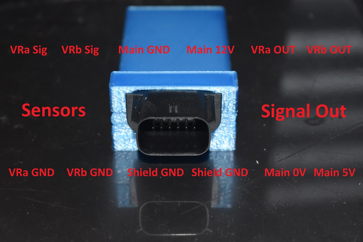
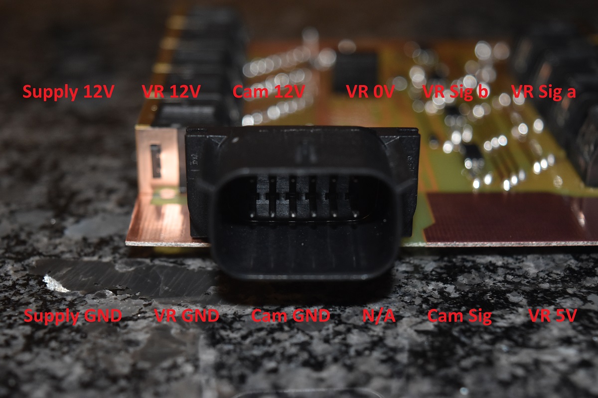
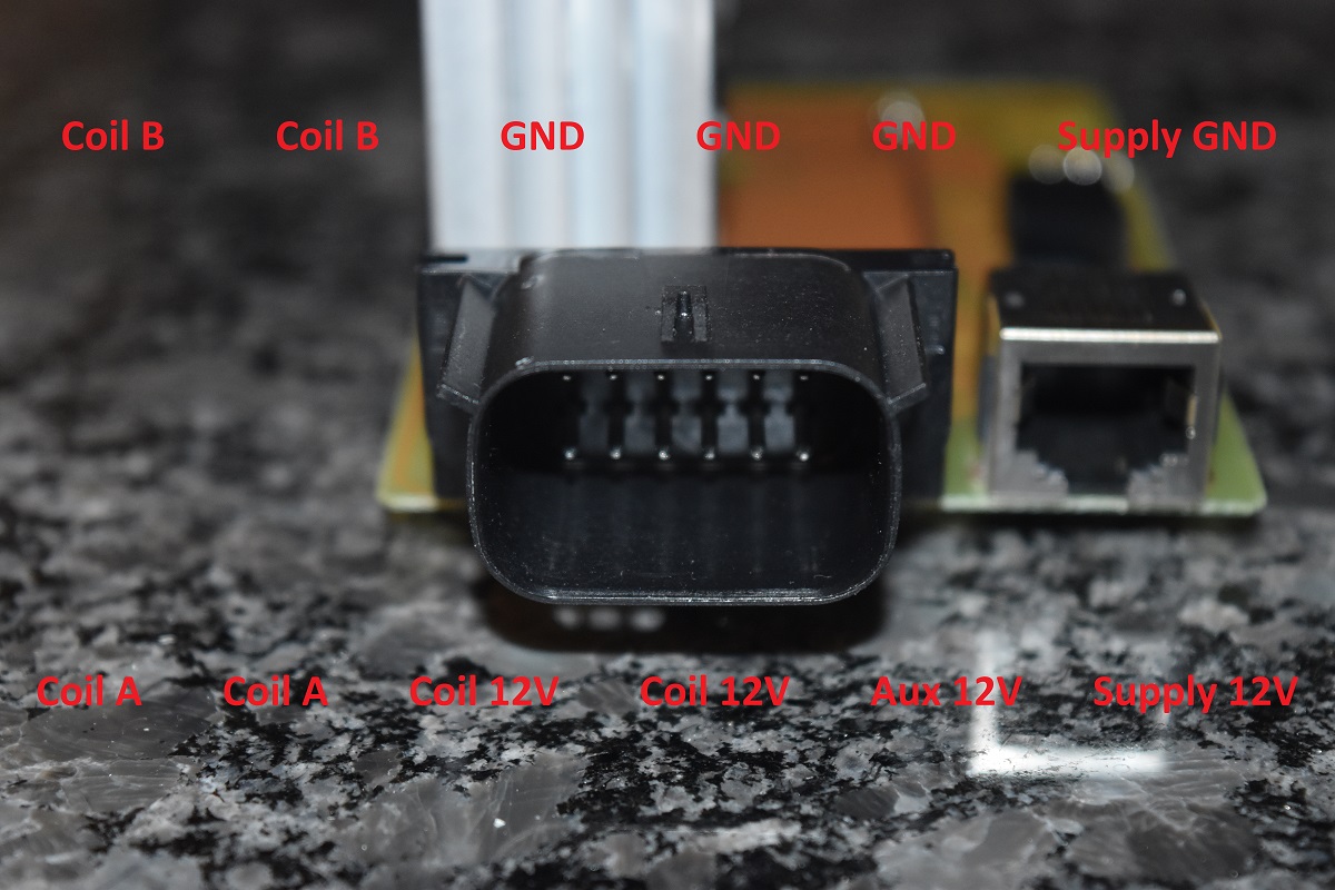
For my own purposes this is the pinout diagram of the main connector.
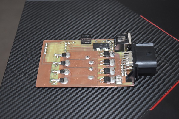
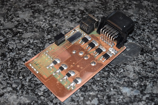
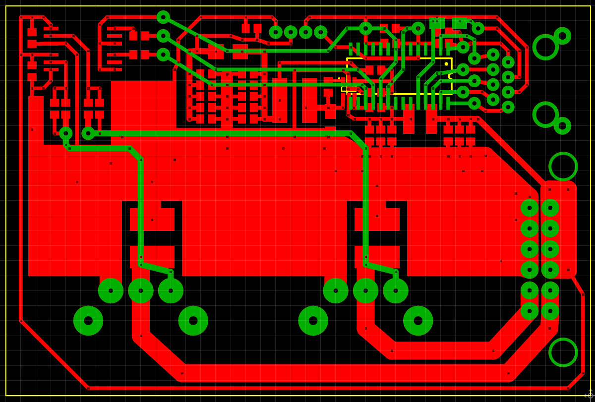
4 Injector Module
This is a fairly simple output module that will drive four injectors. Since this is the first version it does not have any safe guarding features such as short circuit protection, the reason, well it's pointless. If an injector was to fail under load then likely it would cause a lean detonation and destroy the engine anyway. This module again has it's own separate isolated power supply. The control circuit is directly linked to the main control module, the output driving circuit is isolated via optocouplers.
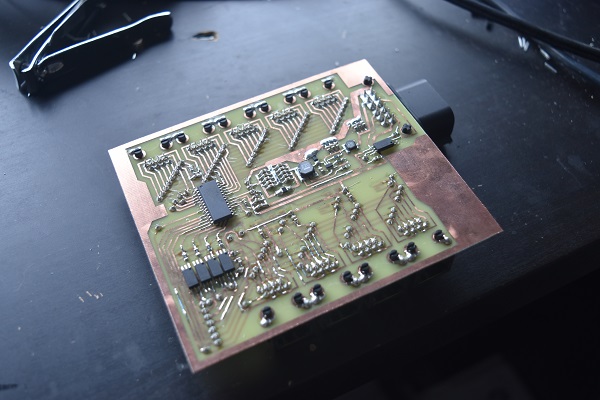
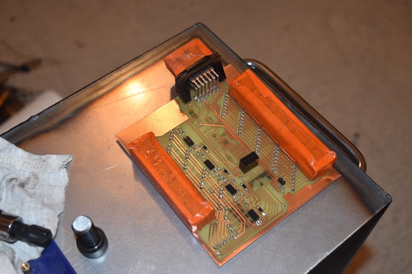
This was the last board I made before I changed the toner cartridge in my printer. I do quite often have to go around the board and touch up areas that either did not develop properly or had a scratch in to begin with. The board to the right is for programming, it has the ICSP header and an RJ45 socket.
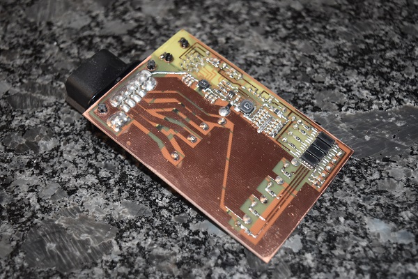
The board assembled.
The problem with copper is that it is very reactive, the moisture in the fingers can tarnish the finish. The board below did not look all that bad until I decided to cover it in a conformal coating. The issue is that solvents cannot be used, it needs to be something abrasive. The reason the board was handled so much was because I spent too much time testing it.
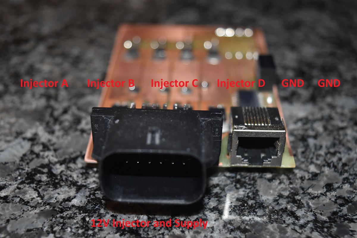
Here is the pinout for my own use.
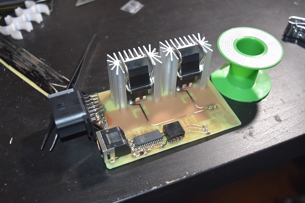
2 Ignition Module
I was not too sure whether to build this module or not simply because I can buy a dedicated one. I finally decided to go ahead so that it could fit in with the rest of the system. The ignition system is very simple because all it requires are two switching transistors in order to control four cylinder using the wasted spark method. The only issue is that a lot of heat can be dissipated by the transistors. I still need to do some tests on my coils to see at what current they saturate in order to determine their maximum operating current. Say that each coil will draw 10 amps and that the voltage drop across my transistors is 2V worst case, they're IGBT's, that means I have 40W in heat to get rid of. It is of course if I choose to run the coils at 100% duty cycle, that is never the case however.
Lets say that the maximum rpm I will run my engine at is 6000rpm (probably will rev limit at 6500). At full speed the engine is rotating 100 times per second, that leaves 10ms per cycle. The dwell time of a coil will rarely exceed 4ms (normally around 2.5ms). That means the duty of the coil is only 40% (4/10 x 100). So at the very worst case the dissipation will be 16 Watts. I would say at a guess for my car that the coil current will probably be 5 amps at a dwell of 2.5ms, that is therefore 5 Watts total or 2.5 watts per coil at full load. It is quite clear that moving this amount of heat will be no tricky task.
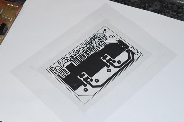
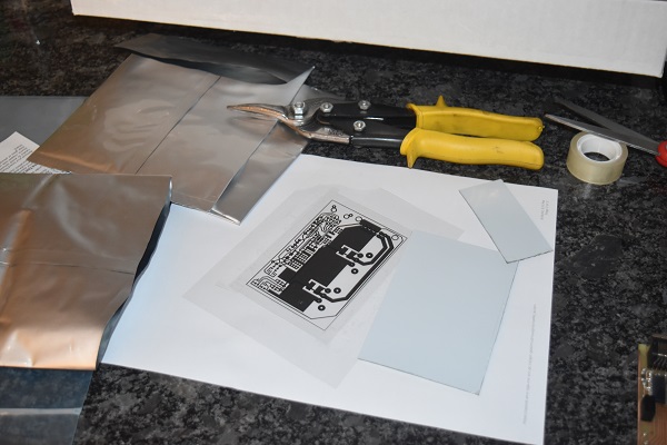
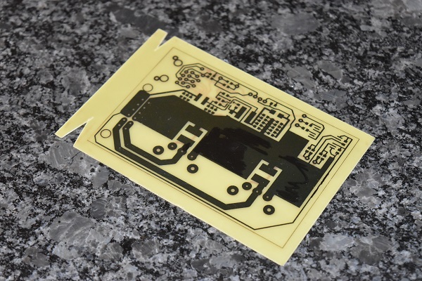
The first step was to print the film, layer and taped it together. I seem to be getting quite a large collection of small pieces of circuit board, I'm sure I'll find a use eventually.
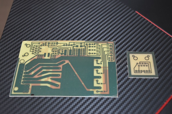
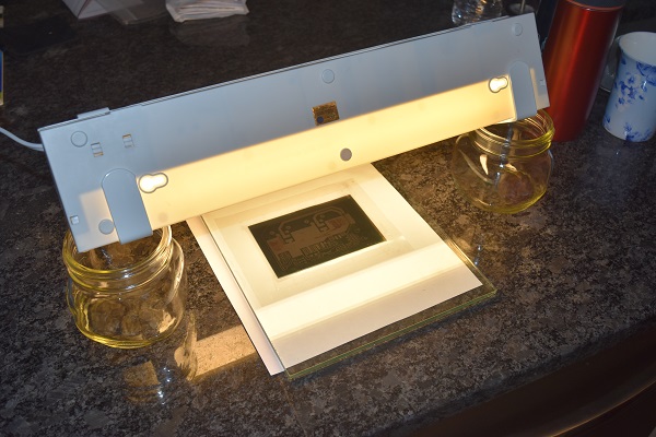
Each side of the board is exposed for eight minutes, it is then developed which leaves the traces behind.
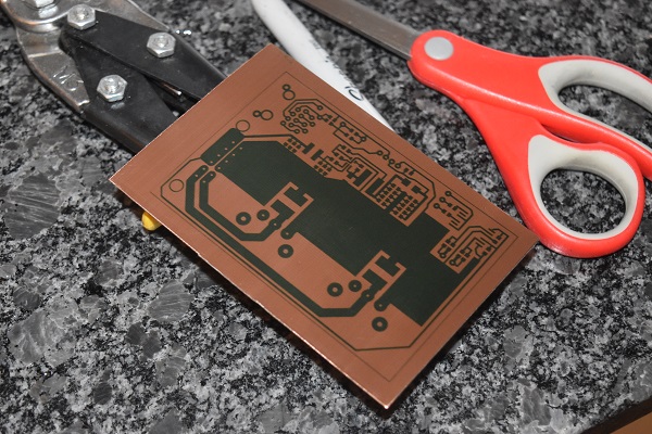
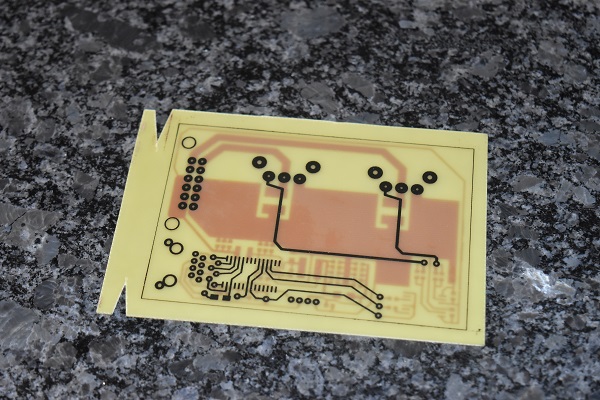
Sometimes there are a few scratches on the artwork, this is solved by colouring it in with a permanent marker. The board was etched in ferric chloride for around 45 minutes. I really do not like to remove such a large amount of copper since it weakens the etching solution. The issue sometimes is that placing large areas of copper tracing can act like a capacitor and cause noise.
It is always a good idea using a larger piece of board than necessary and cutting it down after etching. I often cut boards with a pair of tin snips which damage an eighth of an inch of the photo-resist.
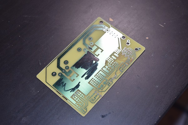
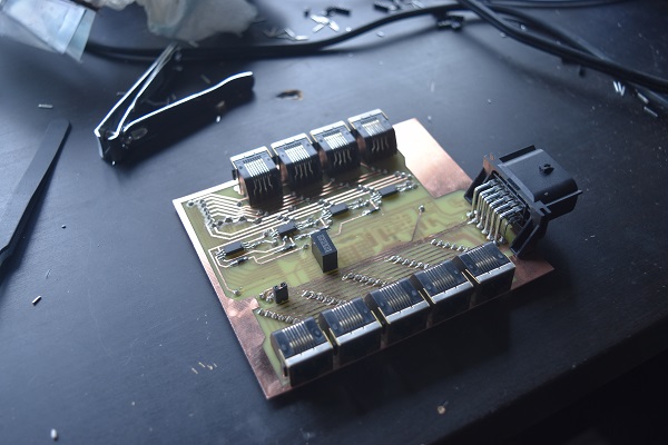
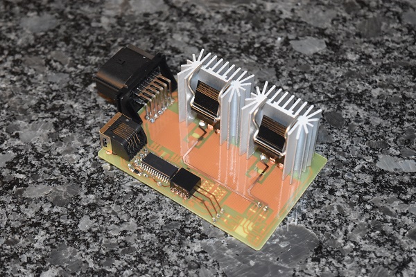
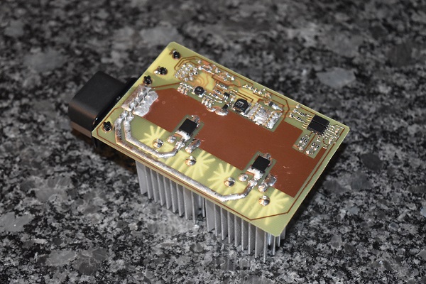
The board was fairly quick to solder since there were few components. I used thermal paste underneath the IGBT's as to best transfer heat.
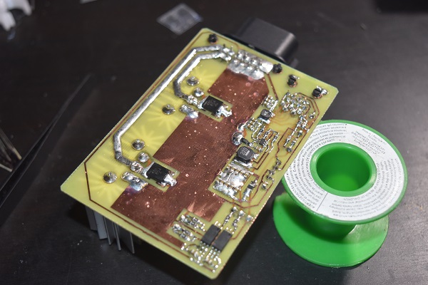
The board was thoroughly cleaned with solvent and then sprayed with conformal coating. I often like how the coating causes the board to become translucent.
This is to aid me in wiring the module.
Auxiliary Module Ver 2
The auxiliary module is for all other outputs that may be required to run an engine or display information. This particular module will be able to control an idle control valve.
In Progress
Auxiliary Module Ver 3
The auxiliary module is for all other outputs that may be required to run an engine or display information. This particular module will be able to control the low current indicators, tachometer, etc...
In Progress
Input Module Ver 1
This
In Progress
Output Bus RJ45 - Control Module
The purpose of the output bus is to send data to all of the output modules.
 1 - Zero Out
2 - Count Out
3 - Negative
4 - Clock Out
5 - Data In
6 - Data Out
7 - Prog (MCLR)
8 - Chip Select
Input Bus RJ45 - Control Module
The purpose of the input bus is to send the engine data to the main control module.
1 - Zero Out
2 - Count Out
3 - Negative
4 - Data In
5 - Ground (Only for Data In)
6 - Data Out
7 - Chip Select Out
8 - Clock Out
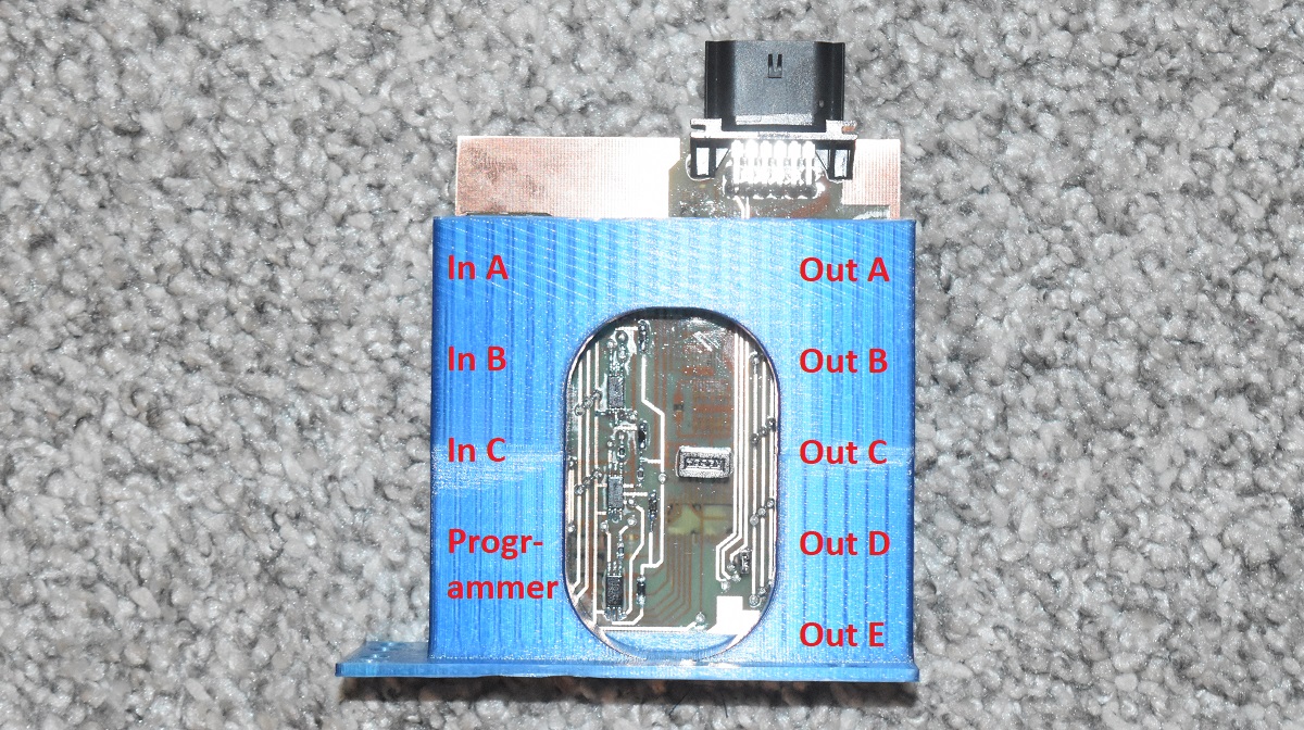
Control Module Ports
These are the locations of the input and output ports for the control module. The programmer has a dedicated terminal which works very much like the input ports, it is polled a lot more than all of the other ports.
Protocols
This is where the real thought has to come into the project as everything must be able to communicate properly. There has to be a set of standards so that a module can be inserted without burdening the system.
Input Module Protocol
1 - Check for Chip Select - When control module turns on this output then it is ready to communicate.
2 - Output Status - RD (Ready), BY (Busy), FT (Fault). Sends status to Control Module.
3 - Wait for response from Control Module - DL (Data Length) How many bytes of data should it read.
4 - Send Data Length - Number of bytes that will be sent.
5 - All od the data to be output.
6 - Control Module drops Chip Select.
Data will be in the form of for each packet of data. A packet of data represents four bytes of data.
xx xx xx xx
The first two bytes represents the sensor ID, the last two bytes is the actual data.
Each output transmission will send ASCII Y(Yes for ok) or N(No, an error or failure)
Output Module Protocol
1 - Set Chip Select
2 - Set Prog
3 - Output ASCII - AC (Output A - Check)
4 - Clock two bytes of dummy data
5 - Check response - RD (Ready), BY (Busy), FT (Fault)
6 - Repeat this for each of the modules (BC, CC, DC, DE)
7 - If all is good then drop the Prog, otherwise a fault may induce limp mode or an engine cut.
8 - Output ASCII - DP (Data Packet)
9 - Output all of the data.
10 - Drop Chip Select
11- If data has to be programmed to the output modules then the Prog output will be set without the chip select.
12 - A , B, C, D, or E will be sent to say which module it wants to program.
Data will be in the form of for each packet of data. A packet of data represents four bytes of data.
xx xx xx xx
The first two bytes represents the sensor ID, the last two bytes is the actual data.
Control Module Protocol
Every 1ms it will check all of the input modules that are in use.
Every zero count it will output the data for the output modules.
Control Module Initialisation Sequence
1 - Power On
Hello, if you have enjoyed reading this project, have taken an interest in another or want me to progress one further then please consider donating or even sponsoring a small amount every month, for more information on why you may like to help me out then follow the sponsor link to the left. Otherwise you can donate any amount with the link below, thank you!