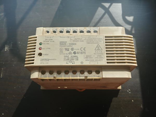
Electronics Troubleshooting and Repair - Omron Switching Power Supply - S82K-10024
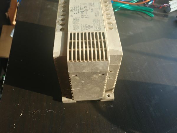
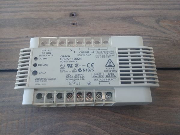
I acquired this power supply in a bundle of non working electronic items. This power supply is intended as a reliable rack mount source for machinery such as CNC lathes, etc... This unit appears to be in bad cosmetic condition and an assumed non working condition. The purpose of this project is to refurbish, test and repair the power supply.
There are many ways to approach a project such as this, the most common would be to replace it with a new unit. It all depends whether the unit is for within the industry or personal use. I would say the only exception to replacing this unit in the industry is if it has to be repaired within hours, the amount of time to invest in this is considerably more than the material worth.
Disassembly and Cleaning
There is a reason this power supply has been removed, likely it is not working. I don't advise powering up any unit until it has at least been cleaned and visually checked. I have seen plenty of examples where an electronic device has failed from dust, moisture or foreign objects. It's not wise to power the unit as removal from it's application may have further moved debris, it could result in further catastrophic damage.
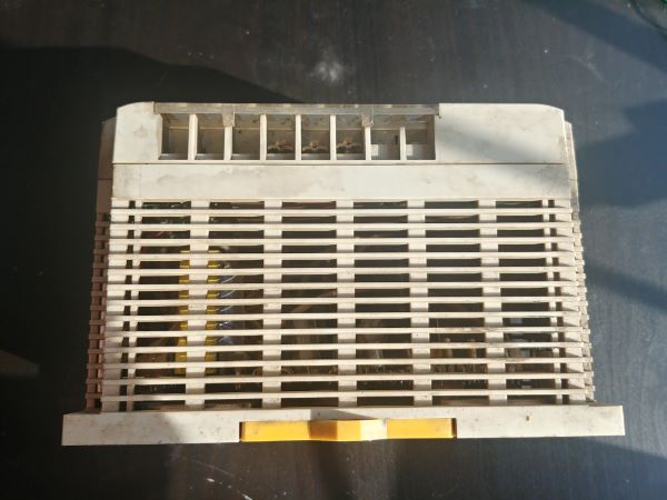
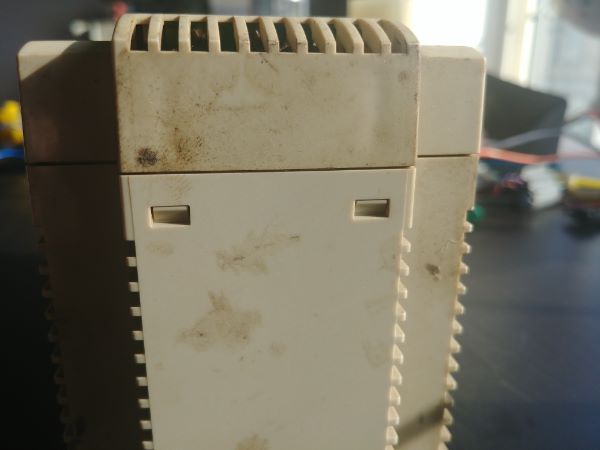
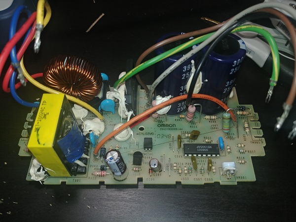
The pictures don't quite do justice of how dirty this power supply really is. The fact that the outside is coated in a greasy dirt means that the inside will likely be too. I'll also add that this came from a CNC machine so it's quite likely this dust could be metallic.
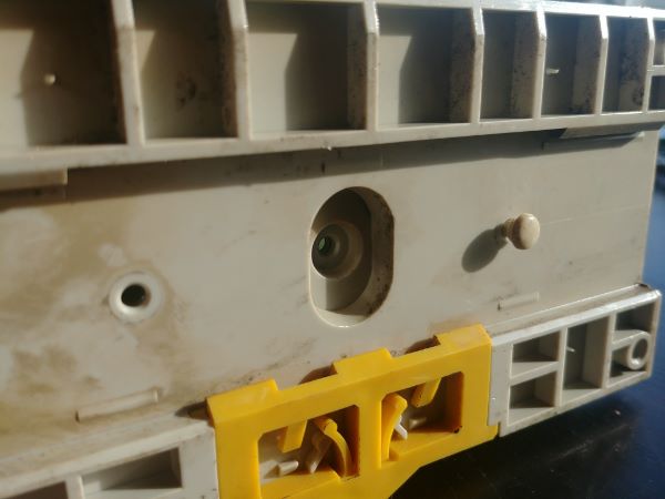
The supply has no external screws and is held together by four clips.
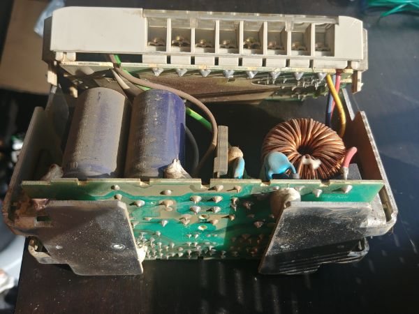
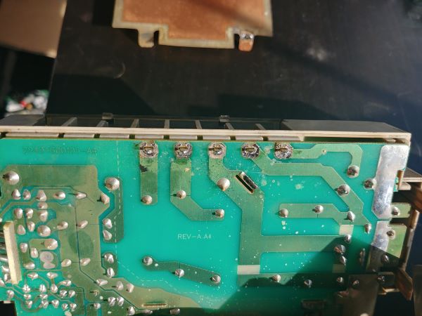
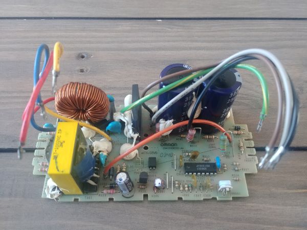
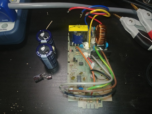
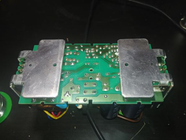
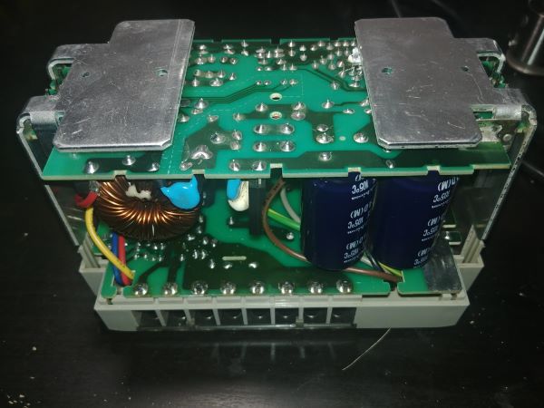
There are three more clips on the bottom which attach to the heat sinks and the bottom of the circuit board. It is quite clear on the second picture that the inside is fairly dirty, take note the colour of the large electrolytic filter capacitors.
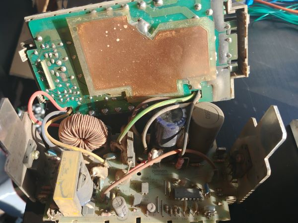
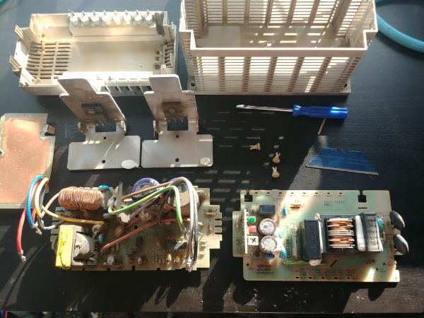
Separating the top board from the bottom shows the extent of the dirt. I used a desoldering station to remove this shield from the top board.
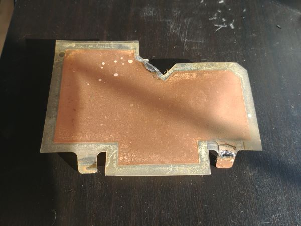
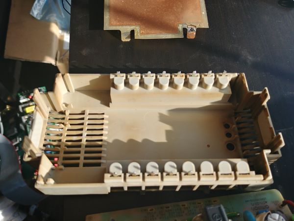
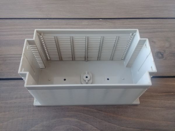
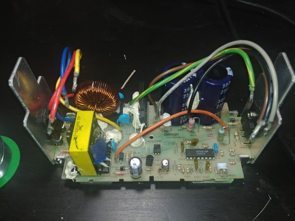
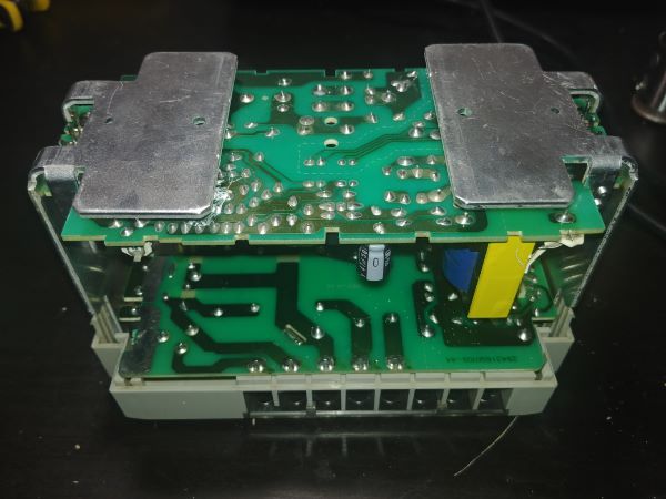
To gain access to the top circuit board the top plastic case needs to be removed. In order to remove the case all of the terminals need to be desoldered from the circuit board, again a desoldering station is a must. It looks as though the plastic is discoloured but is in fact a greasy residue.
I separated the top circuit board from the bottom, this required me to desolder seven wires. I also removed the two heat sinks along with the large semiconductors from the bottom board. There are a few odd conflicts with the design of this power supply, not the electronics but the way it is constructed. The unit has to be dismantled in a particular order and it requires a desoldering tool. The reason this is unusual is because this cannot be serviced by the common service technician, certainly not out in the field. However the way the unit is put together it is obvious that it can be serviced and is not a throw away item.
If the manufacturer didn't want this to be serviceable at all then it would have been glued together. Also the way that the terminals are soldered from the top case to the top circuit board shows that it is meant to be accessible, if not then they would not have placed slots in the through holes, these slots make solder removal really easy, also the legs are not bent over. All of the wires have crimped solder terminals which do not snap into the holes (note the crimps are also for vibration resistance). Lastly the large semiconductors don't have holes for the legs but slots, again making them very easy to remove solder.
Clean and Inspection
The very first step after dismantling the unit is to give a quick inspection of catastrophic failure. If for example there is a large black hole through the middle of the board then it's pointless continuing, unless absolutely necessary. The second step is to thoroughly wash all components of the unit, the cases and the boards. A thorough scrub in a soapy detergent and a thorough rinse is all these boards will need. If there were any carbon deposits present from a damaged component then I would have to use something a little more harsh. One thing for certain is that no solvents should be used.
All components are to have a visual inspection, this is possible signs of a failure, basically anything that looks different from new. Fuses, is the filament broken. Electrolytic capacitors, are they bulging from the top or sides, is it lifted from the board, has any dielectric leaked. Ceramic capacitors, any holes in the middle or chipped ceramic. Resistors, dark in colour or the bands hard to read, heat causes them to fade. Transformers, any burnt insulation. IC's, holes in the top or cracks. Wires, molten insulation or loose crimps. Semiconductors, holes or cracks in the cases. Circuit board traces, any lifted or burnt tracks.
Here are the cases cleaned, there is barely any discolouration and they look almost new.
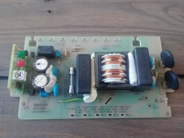
The top board looks to be in excellent condition, no obvious failures. There is a protection device, a glass fuse, this does not seem to have failed and all other components look to be fine.
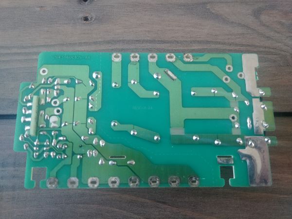
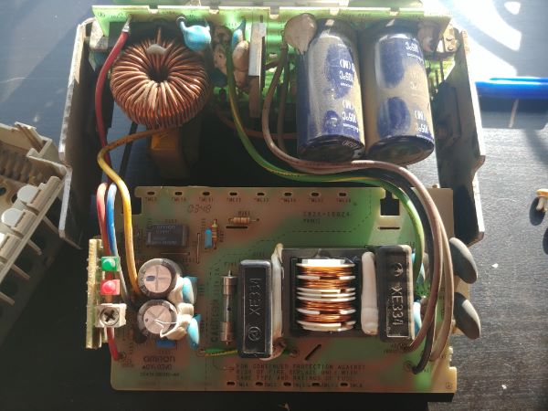
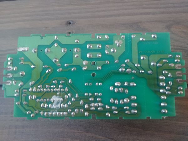
The bottom board looks to be in excellent condition, no obvious signs of failure.
It is strange that everything seems to be in excellent condition and there are no obvious signs of a failure. I would have at least expected the fuse to have failed, a quick check with a continuity meter confirms it is ok. There are now two options depending on whether the unit needs to work for now or continue to work for many years to come. If I did not have to desolder so many components to disassemble the unit then at this point I would just power it up to see if it works. Every time something is soldered to the board it weakens the pads, so in this case I'm going to test all the components before reassembly.
Component Testing
Now we're going to assume that we want this supply to function for many more years. All components have a particular life span, thankfully most of them are very very long. The only components we really have to worry about in common electronics are electrolytic capacitors, anything mechanical or containing a chemical solution. The only components in the whole of this supply is the relay on the top board and the electrolytic capacitors throughout the board. I can say that for now I don't need to remove and test the relay as this is not directly related to the supplies operation. An exception to this rule is any semiconductors doing any kind of power switching or rectification should also be checked. Anything that may be subject to transient voltages such as components in the filter circuitry should also be checked, their sole job is to protect the rest of the unit.
So, all electrolytic capacitors are to be removed and tested. The power transistors are to be removed and tested. The bridge rectifier is to be removed and tested. The supply filter capacitors are to removed and checked.
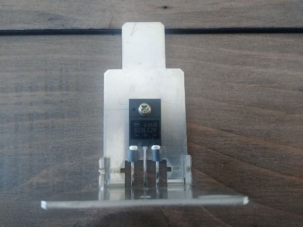
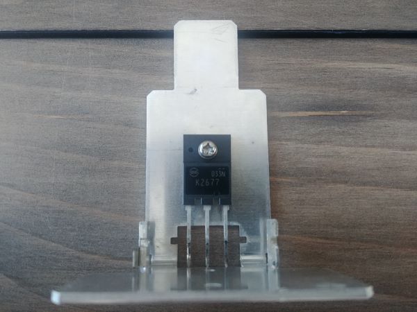
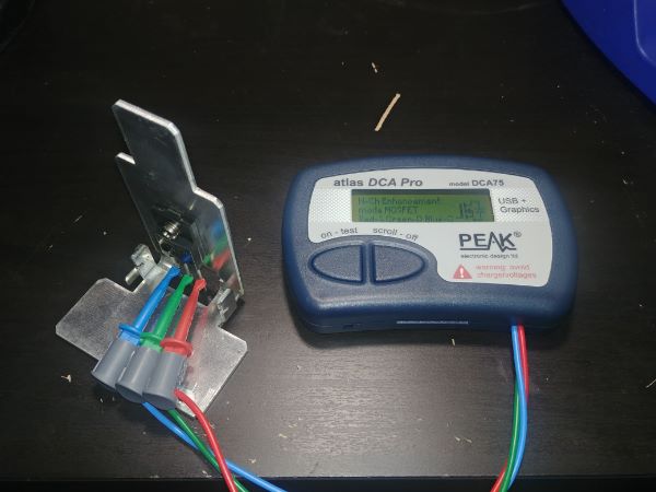
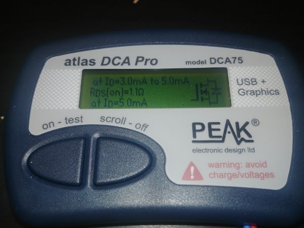
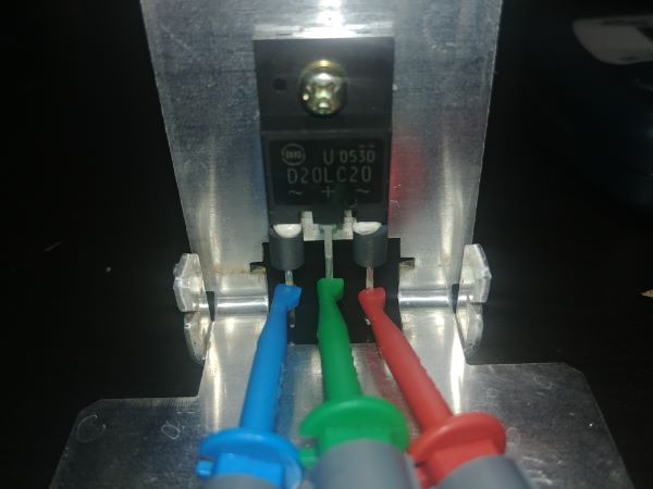
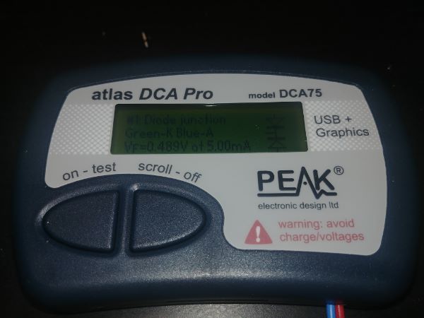
The first parts I would check are the switching semiconductors since I had to remove them to gain access to the board. On the left is a D20LC20 dual diode package and on the right is a K2677 MOSFET, rated 900V at 10A.
I bought this meter a while back that will identify any semiconductor with either two or three legs. It does not matter which way the leads are attached as it will test all parameters independently. The only problem with a unit such as this is that it can only apply small currents and doesn't give any useful information on larger semiconductors. The reason I use it is that it will tell me what the component is and if it is good, especially helpful when a data sheet cannot be found on the part number.
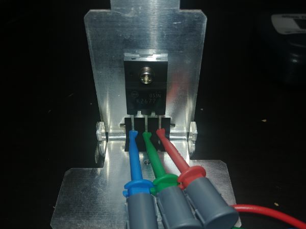
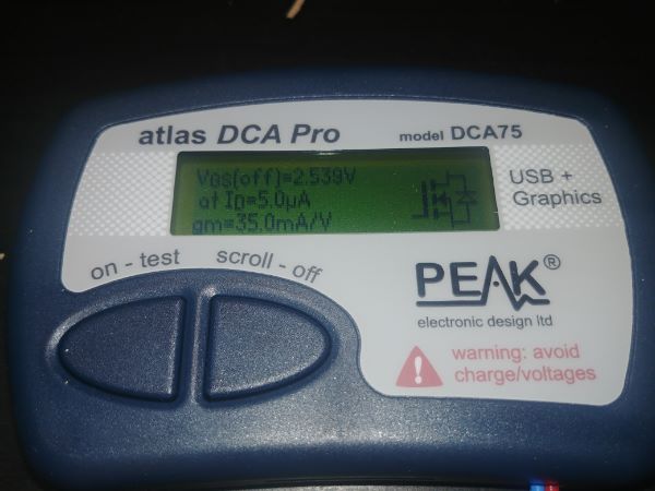
The first readout tells me that the blue connector is the gate, the green is drain and red is the source. Nearly all of the MOSFET's I've encountered have this layout on the pins, but it's very useful when a manufacturer chooses a different approach. The rest of the data tells me at what voltage the FET turns on at a particular current and what voltage it turns off. Again these results are not always so accurate since a higher voltage may be required when switching a larger current, evident from component data sheets. I will say that for MOSFET's of this size and smaller it has proved fairly accurate, but for IGBT's it's been quite a way off.
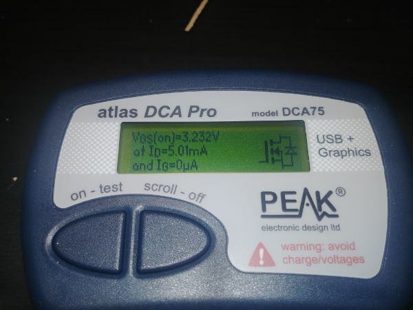
The data sheet says the Rds on is typically 1.04 ohm, 5A at 10V gate. I have to admit that this unit is displaying rather accurate results and that all the readings are well within the specifications. I can conclude that this component is in perfect working condition.
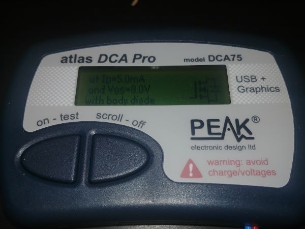
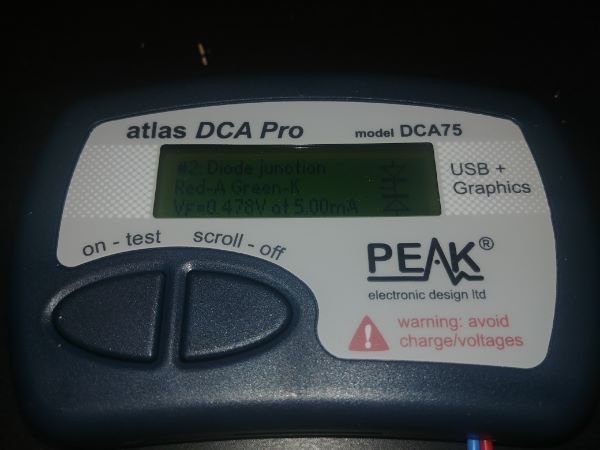
The meter again correctly identifies that this is a common cathode, dual diode component.
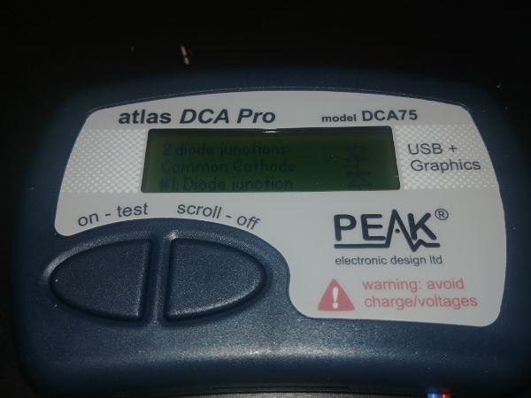
The voltage drops on both are very similar. Taking a look at the data sheet it is a super fast recovery diode rated 200V at 20A. This unit says the forward voltage drop is 0.5V at 5mA, again the drop will increase as the current increases. According to the data sheet the forward drop will be 0.55V at 100mA. The meter in this case is only an indication of what the component is and that it is in perfect working condition, the results are of no use.
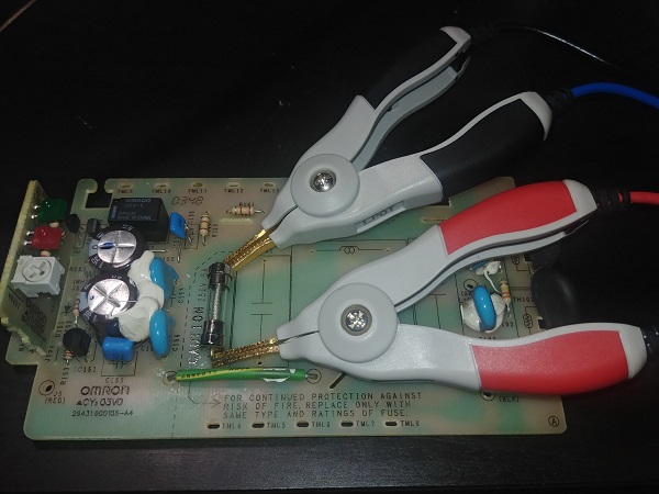
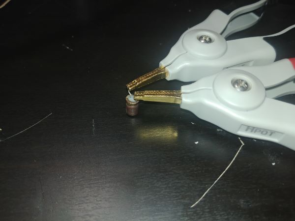
The most important piece of equipment when troubleshooting any device such as this is a desoldering station, it literally sucks the solder from the pad and makes component removal super easy. In this case I'll be removing the film filter capacitors in the supply as these are the first defense against voltage transients.
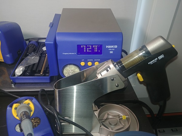
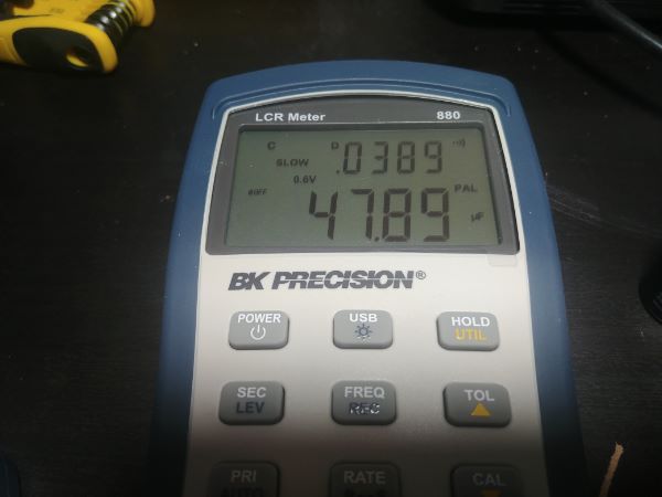
I removed both the filter capacitors and the filter in one shot as I did not want to cut the silicone. The next most important piece of equipment is a high accuracy LCR meter. This meter not only tells me what the component values are but also gives me an indication to if it has degraded or failed. I'm pretty certain that none of the capacitors have failed in this unit as the cases almost always rupture and cause a huge mess. Even knowing this, by removing these components and testing them I can predict if they're on their way to failure or indeed are in perfect order.
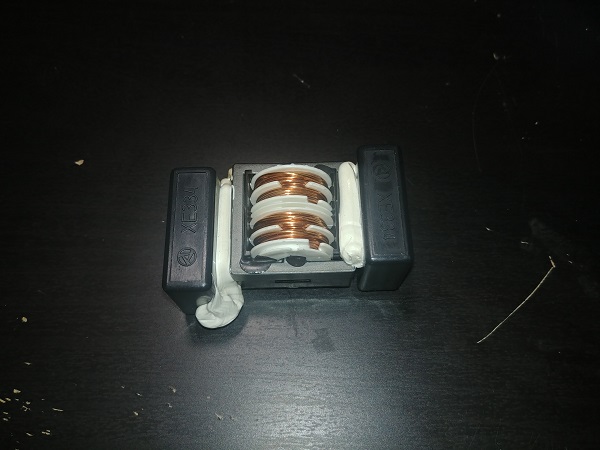
Depending on the type of capacitor will determine what frequency it is to be tested at. The difference between all capacitors is their ESR ratings (Equivalent Series Resistance). As the switching frequency across a capacitor is increased, so does the amount of energy lost which results in heating. In the data sheet of a capacitor is something called the "dissipation factor", this is how much energy the capacitor can loose before failure. Ceramic capacitors have low ESR's and can handle high frequencies, film capacitors are mid-range and electrolytic capacitors have fairly high ESR's and can only handle low frequencies. The whole purpose of this filter at the supply is to remove these high frequencies so that they don't cause the electrolytics to fail prematurely.
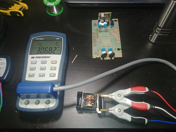
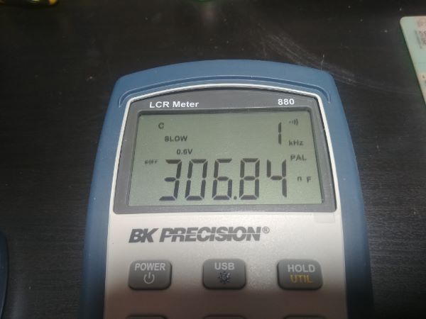
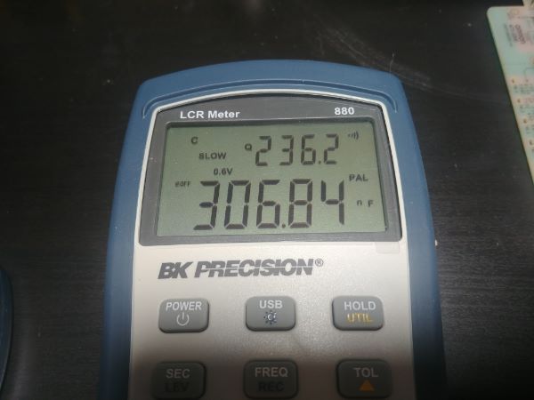
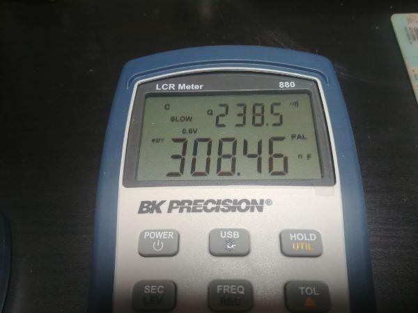
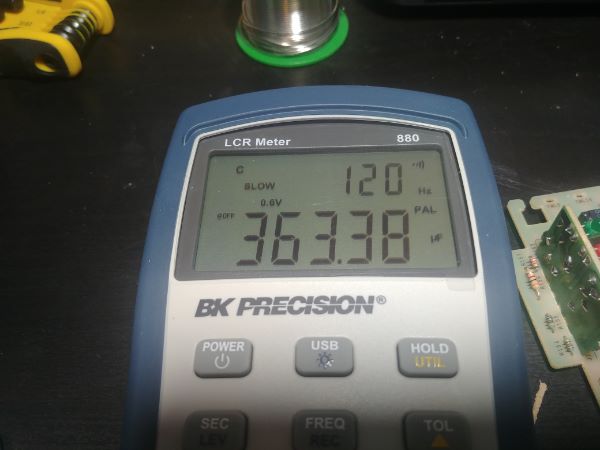
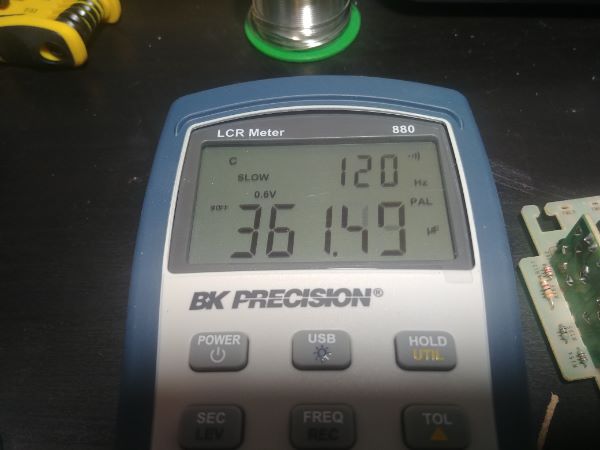
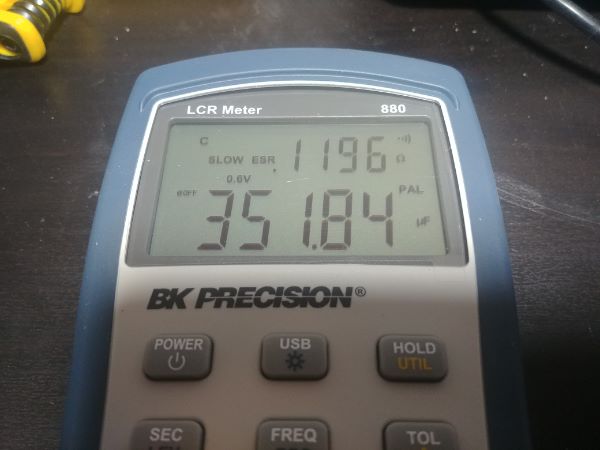
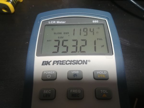
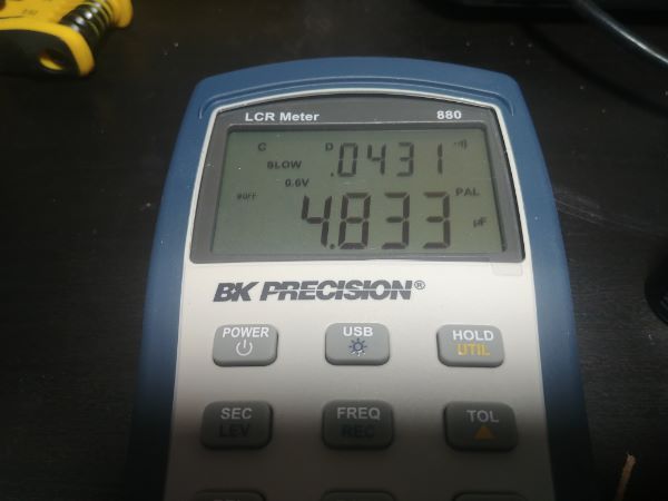
The higher end ESR meters will allow the user to measure the ESR, dissipation factor and quality factor of a capacitor at different frequencies. So electrolytics will be measured at 100 or 120HZ, film capacitors 1kHz, and ceramic capacitors 10 to 100kHz. This is a film capacitor and should be measured at 1kHz. Luckily I managed to find the data sheet for this exact component and can confirm the dissipation factor is 0.01 maximum at 1kHz.
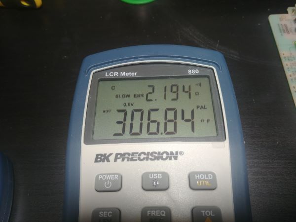
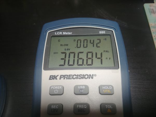
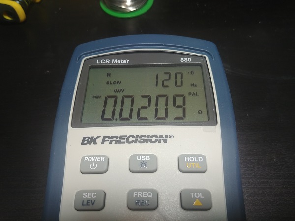
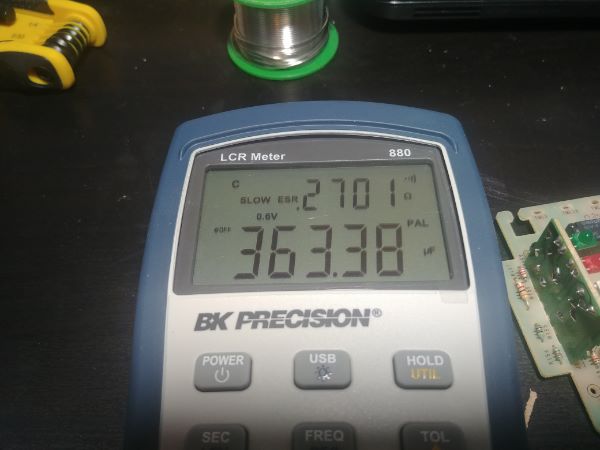
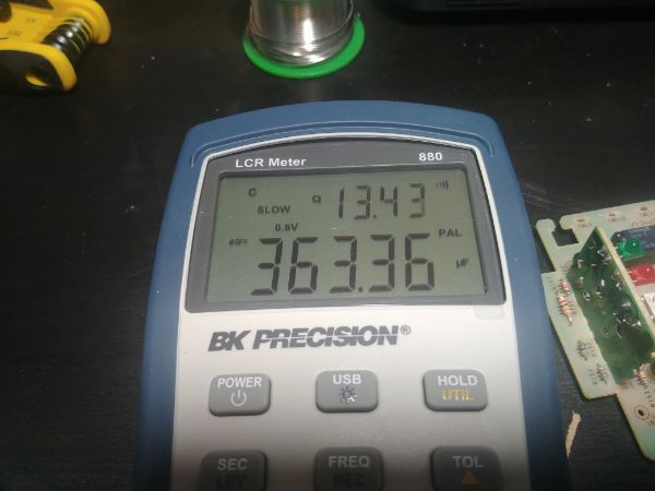
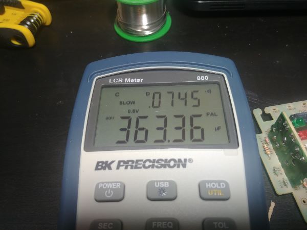
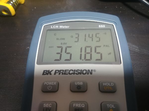
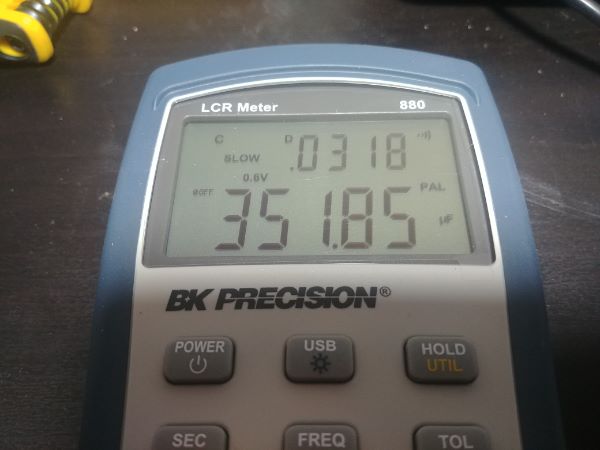
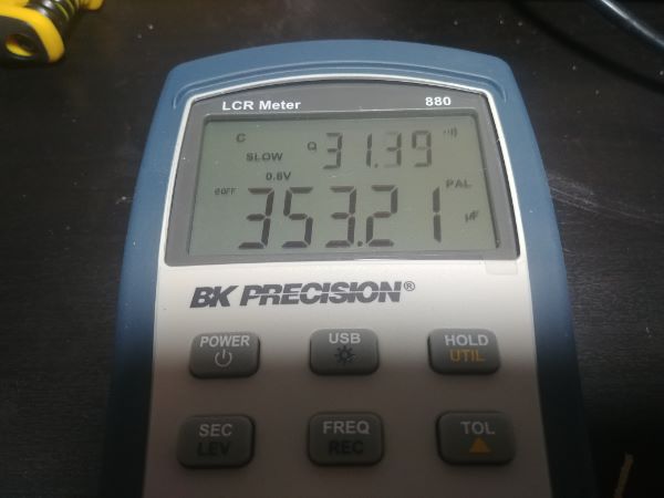
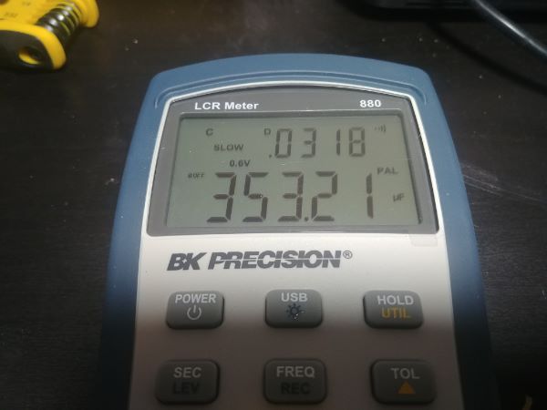
The first capacitor is measured at 306.84nF, the specification is 334, also known as 330nF. The tolerance given is 20%, it is therefore well within tolerance. The ESR is 2.194 ohm, not given in the data sheet. The quality factor 236.2 and the dissipation factor 0.0042. Note that the quality factor is just the reciprocal of the dissipation factor, it is well within specification.
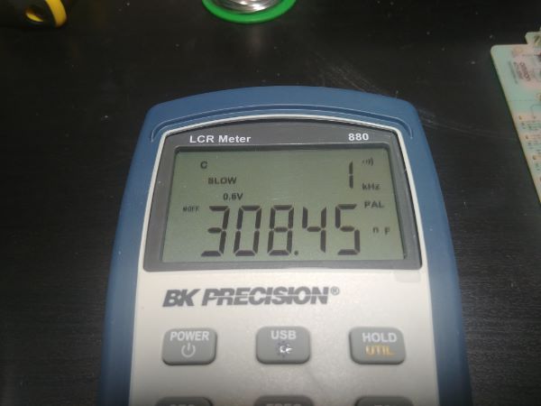
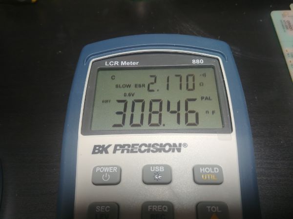
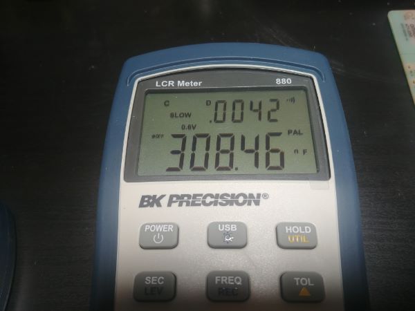
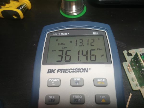
The second capacitor measured at 308.45nF with a 0.0042 dissipation factor, again well within tolerance.
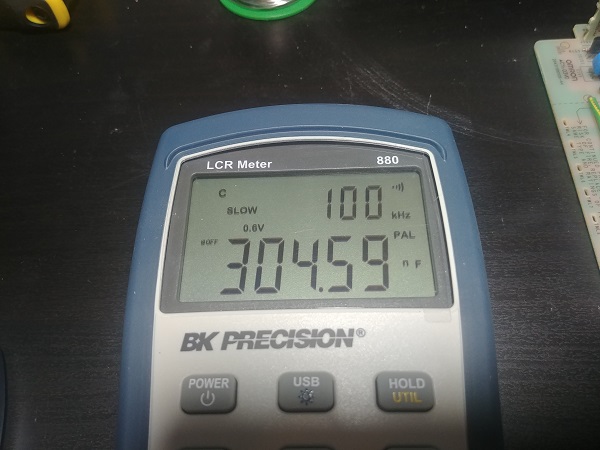
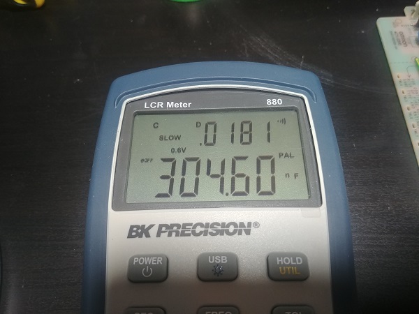
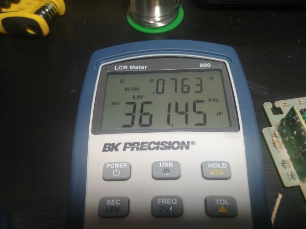
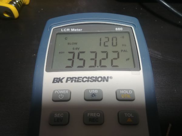
The determining factor to whether a capacitor is good, failing or bad is the dissipation factor. As the component wears it's ESR will start to change and the dissipation factor will start to increase. This increase means more power is being lost as heat in the component, as the heat rises the degradation will progress faster. Once a component starts to produce more heat than it can dissipate then it will fail, this is often seen by ruptured cases. So for example if I were to test this capacitor at 100kHz which is far about it's operating frequency then it should have a high dissipation factor, as proven by the results below. If there were such frequencies present in the supply then this would be a reason for failure. Take note of all the blue ceramic capacitors strewn around this unit, these are to deal with these even higher frequencies, they are almost always reference to earth / ground.
This meter can also perform a simple task like the continuity of a fuse, this component never failed, which is very odd.
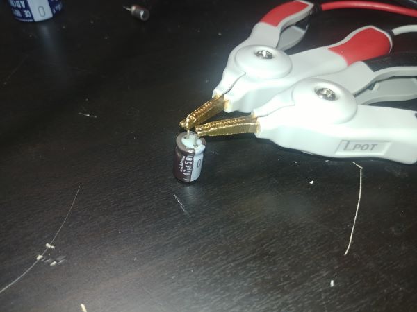
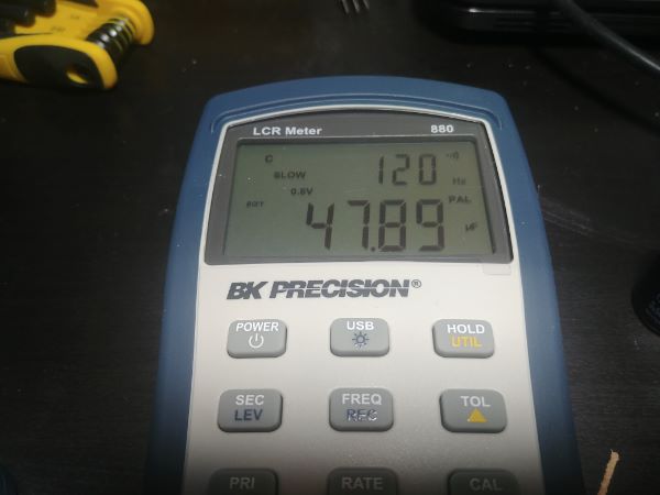
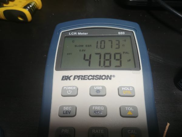
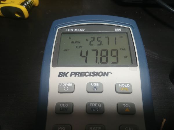
Next to test are some small filter capacitors for the output. I won't be testing the ceramic capacitors as these almost never fail, nor would they stop the supply from working if they had. The capacitors are 390uF, 35V electrolytic Nichicon, a well respected manufacturer, unfortunately often faked too.
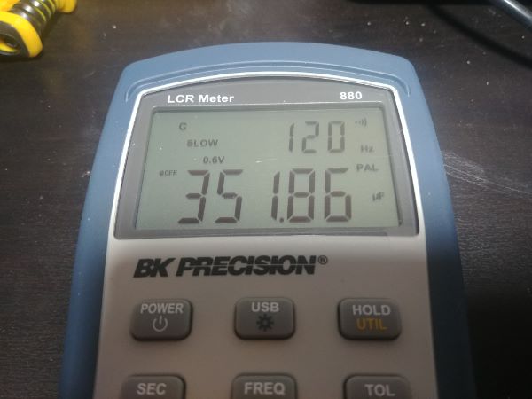
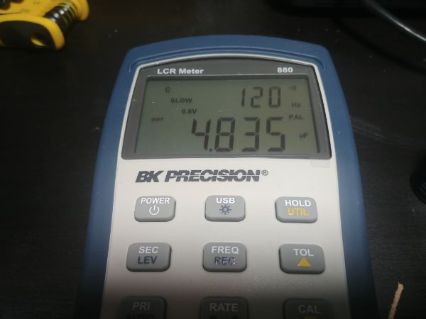
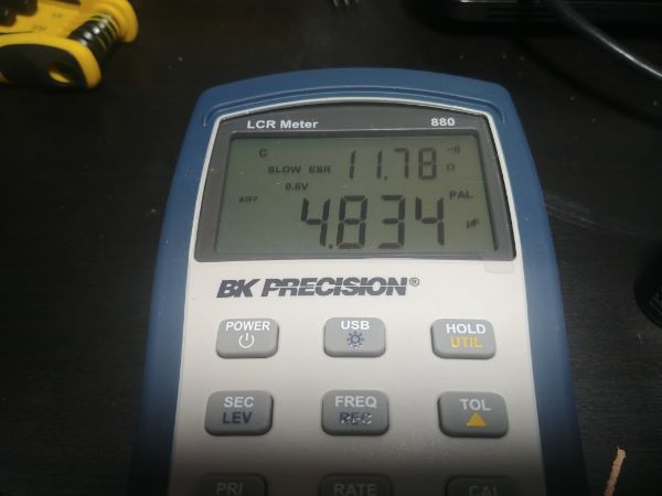
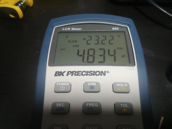
Electrolytic capacitors have very poor ESRs with respect to all other types of capacitor, what makes them great is their capacity and cheap construction. I managed to find the data sheet for these capacitors, the dissipation factor maximum at 120Hz is 0.35. Something to note with electrolytic capacitors is that their dissipation factors are either tested at 100 or 120Hz, double the line frequency depending where in the world. Often 120Hz takes president as this will be the worst case, the reason it is double is because many are run through a voltage double which also doubles ripple frequency.
The capacitance for both are well within specification as well as the dissipation factors. Sometimes it can be hard to determine whether a component should be changed or not. I would say that if the dissipation factor is less than 50% of the limit then it can be left alone, however if it is approaching the limit then it is advisable to replace it. Also when there are multiples of the same components such as in this case, if the measured values are completely different then it would be a sign that one is leading to failure. If the components like in both these examples are measuring almost the same and well within tolerance then we can assume they're perfectly healthy, and likely to last a long time.

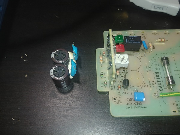
I was happy with all of the components on the top board and moved to the bottom board. Just four electrolytics and a large bridge rectifier. Since the bridge rectifier is glued in place it will mean more work, this is one of those components I can test if the unit does not work, remember I'm checking the most fragile components first and determining their life span.
These two filter capacitors are often open to a lot of abuse. Since there is a good filter circuitry on the input they won't be exposed to high frequency inputs. However, they will be subject to ripple currents from the switching circuitry. The larger this capacitor bank is, the less amount of ripple that will be seen, that is the difference between the high and low voltage peeks. If the ripple is very high then the capacitor is continuously charging and discharging leading to power dissipated. If the ripple remains small then little heat will be dissipated. So if a power supply is run at it's limit where this ripple is high then these capacitors won't last as long as if the load was more gentle. To combat failures the manufacturer will use upgraded materials, the temperature rating and working life will be much higher than that of a standard capacitor, at an additional expense.
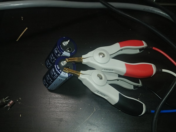
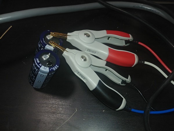
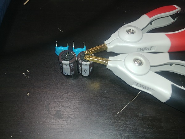
These two capacitors are rated 250V at 390uF. According to the data sheet the dissipation factor should be within 0.15 at 120Hz. I often find that the capacitance values are towards the lower end of the tolerance, maybe that's the manufacturer saving money. The dissipation factors are well within tolerance and both are exactly the same, these are in excellent condition.
These two smaller capacitors on the board are subject to less strain. They are both smoothing capacitors, one of them for the control circuit and the other for the feedback circuit. All measurements are well within specification, they are healthy.
All of the fragile components or those that are subject to more strain have all been tested. I'm confident all the capacitors still have a lot of life in them and that this unit will work for many years to come. What troubles me is that there is not a single sign that this supply is damaged or non working. If it does not work when assembled I would then remove the transistors to test, if these are ok then it could only be the control IC. Regardless, I'm happy the unit is clean and can be assembled, powered and tested.
All of the components were soldered back in place. The only thing I did not do was glue the capacitors since that if it does not work I won't have to wait for the silicone to dry.
Basic Testing
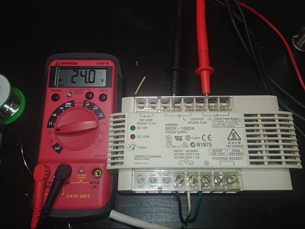
The basic testing is powering up the unit once I'm happy it's clean and all the fragile components have been checked. A complete assembly of the unit is not necessary as if it does not function then I would be adding extra time to the service. I powered up the unit and it worked perfectly, I trimmed the voltage from 24.2V to 24V. I also checked the relays operation, when powered it is open and when unpowered its contacts are closed.
The unit is in perfect working condition, I'm however quite disappointed that I didn't have to search deeper.
Circuit Diagram
For 99% of any electronic items out, there won't be a circuit diagram. The exception to this rule is if you work for the manufacturer or if fixing an electrical machine, not electronics. I would say that if a basic understanding of the item is met and all the passive components can be checked, a repair will be successful in most cases. The only exception to this may be if an integrated circuit has failed and the technician needs to know what to check for. I can't say this is an easy task, considering someone may have spent weeks or even months designing something like this.
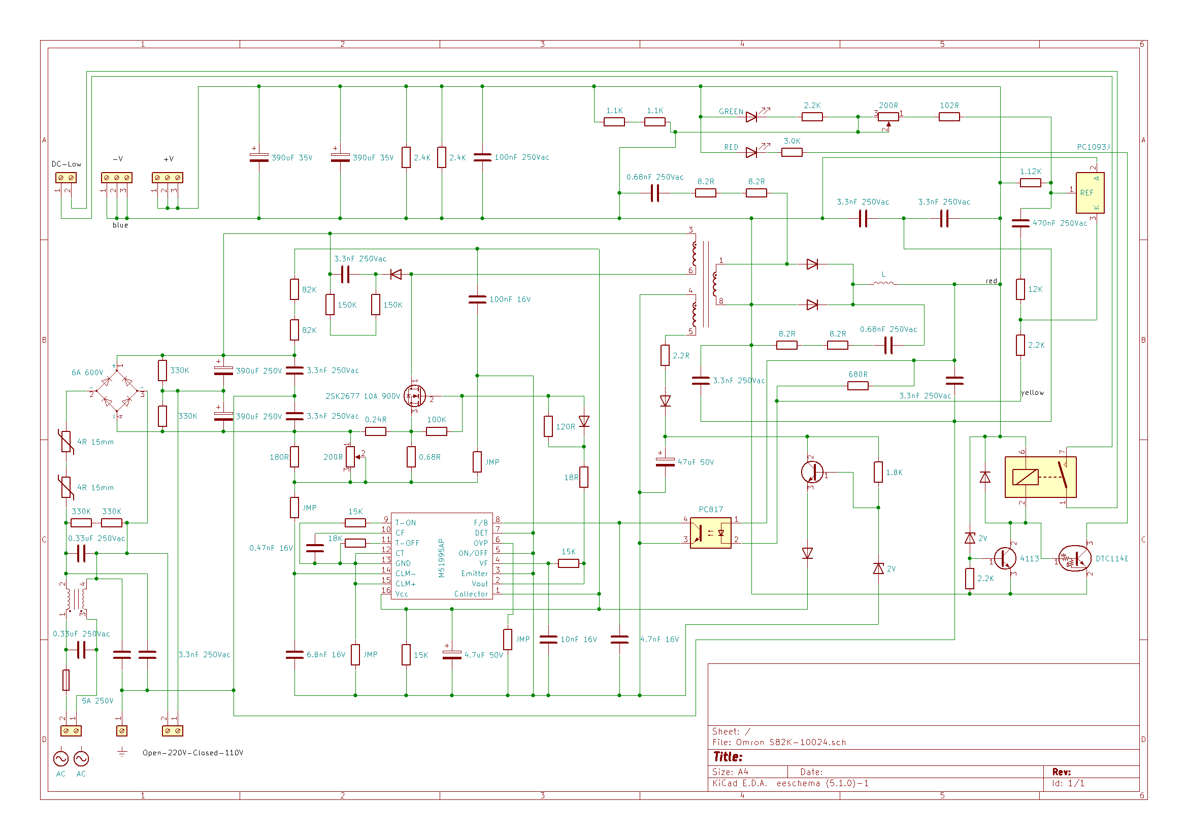
Since I want to demonstrate how this unit works, and the fact I found data sheets for all of the components, I chose to map a circuit diagram. I will say this diagram is accurate and most component values have been labeled, I hopefully made no errors.
How it Works
This is a simple switching power supply, I'll do my best to explain how of each part of the circuit works. The benefit of a switching power supply compared to a transformer driven supply is that it is more compact, less noisy (sound and RFI), produces less ripple, accurate regulated voltage, over-current protection and generally very efficient.
 The first part of the supply is the power section, this changes the supply AC to a smooth DC supply.
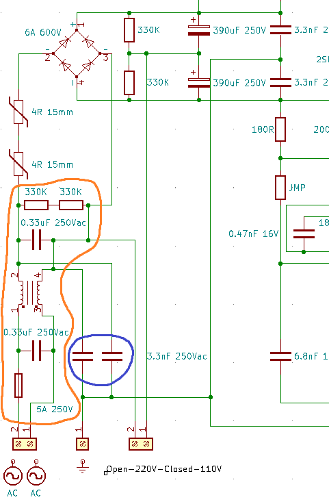
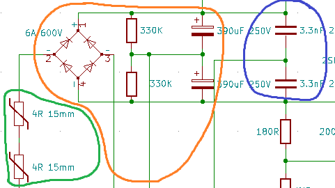
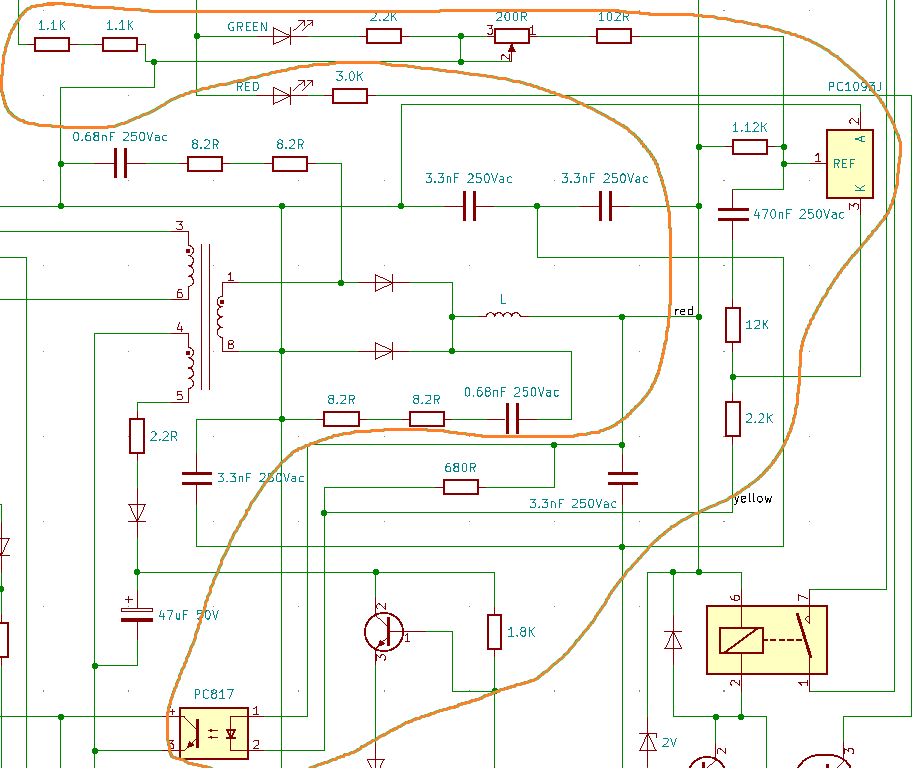
As circled in orange, firstly the supply AC is passed through a glass fuse, in general this is a slow-blow fuse because of initial inrush current when powering on the supply. This would always be the first thing to check when repairing a supply, this almost always blows when a filter capacitor fails, a switching transistor or a short. If this has not failed but the supply is not working then generally it is the control circuit that has failed.
The supply has filters, a few different types which help to reduce high frequency noises and voltage transients. First is a film capacitor placed in parallel with the supply, as frequency increases the impedance across it will decrease. So for example the supply will be 60Hz maximum which is an impedance of 8k ohm, it will only have to take 15mA of current at 120Vac. Or, at 50Hz, 230Vac, 24mA. The idea is that any high frequencies such as 1kHz will be absorbed by the capacitor, at these frequencies the impedance would be 482 ohms, a lot lower resulting in 250mA current peaks. These high frequencies are often caused by other switching devices which are associated with inductive currents and high voltage transients produced. It is quite clear now that if the frequency is high and the voltage is high that the capacitor will draw a lot of current between it, this filter catches these peaks before they get to the switching transistors. This type of capacitor filter is known as a "differential mode capacitor filter" as it's placed across a supply.
The two capacitors circled in blue, which are throughout the supply are connected between a line and ground. These are known as "common mode capacitor filters" as they have the ground in common. These capacitors are ceramics which can work at very high frequencies, they catch the very high voltage transients.
The inductive filter in the middle of the orange circle is known as a "common mode inductive filter" or a "common mode choke". The windings are passing in the same direction, the power passing through it is common. The magnetic fields induced by each winding will cancel each other out.
So why are all of these filters used. In short the capacitive filters catch the high voltage transients whereas the inductive filter catches the high frequencies which can lead to high voltages. The two resistors after the filters are to bleed the capacitors.
 The next important part of the supply is that which provides the switching circuit with smooth DC.
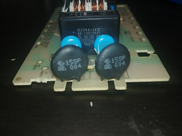
Circled in green are some NTC thermistors which limit inrush current. At room temperature they have a resistance of 4 ohms each, and limit the current to charge the large filter capacitors. They will quickly rise in heat to which the resistance will drop to almost zero, this happens fairly quickly as any current passed through a resistor will dissipate heat. If these were not present then it would almost be a short circuit initially when charging the filter capacitors. All wires are inductors and any high currents will produce a voltage spike, potentially a damaging one. Also the current has to pass through a bridge rectifier, again the instantaneous current may destroy them. This design has chosen two thermistors which in theory is not necessary, the reason is that two small components are less prone to vibration damage as opposed to one large component. These get hot so holding them with a glue is not particularly favourable.
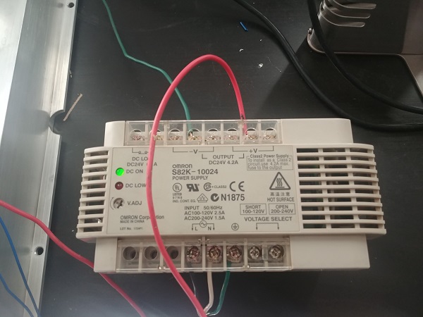
Almost all power supplies will be dual voltage, they can be supplied with 120V or up to 240V. Do not confuse these supplies with those in laptops that can accept voltages of anywhere from 80 to 250V, they are constructed differently for a reason, as explained in another project. The bridge rectifier and two capacitors serve a very important purpose of not only rectifying the AC to DC and smoothing it, but a voltage doubler. There is a twin terminal on the supply that says. "short 120v and open 240V". If left open the capacitors will be charged to rectified 240V, if closed then the circuit will act as a voltage doubler. In the end the voltage across the capacitors will be the same, as long as the supply is wired correctly. Of course if powered by 240V and the terminal was shorted then it would double this voltage, this would likely result in catastrophic failure. The two resistors in the circuit are to bleed the capacitors after power down, a safety aspect.
The last part circled in blue is another common mode capacitive filter, this is the last line of defense for the electrolytic filter capacitors.
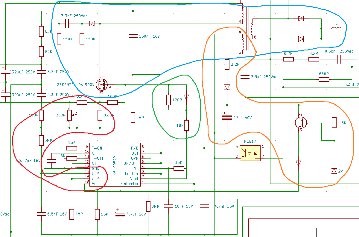
The main switching circuit is circled in blue. To the top left is a snubber circuit that removes any high voltage transients, MOSFET's are very fragile towards high voltages. To the top right is the transformer that steps the voltage down, on it's output stage is a pair of ultra-fast rectifiers. After the rectifiers is an inductive choke which stops high frequencies from passing, after all the circuit is switching at hundreds of kilohertz. To the bottom is the switching MOSFET itself, it is rated far higher than what it is switching at. For one a very high voltage rating is required, more than double it is switching at just incase the snubber does not do it's job. The current rating is also much higher than operating, this is so that if there is a short on the units output then the control circuit has some time to react before the transistor is destroyed.
The orange circle is the power supply for the control circuit. The current is rectified to DC with a diode and limited with a resistor in order to charge the capacitor. To the right is a simple voltage regulator consisting of transistor and zener diode. The zener diode determines what the voltage is supposed to be, it will almost keep the transistor in a quiescent state, neither on or off. It is quite an inefficient way of regulating a voltage, it is however simple and the power lost is negligible. Also note that the value I have on the zener is not accurate, so you have to read this description in order to size it correctly. I could remove the diode and test it, or I can measure the regulated voltage when powered, so read on to find the value. The two 82K resistors in series from the supply bus down to the control circuit is to give it power to start up, initially.
The red circle is the current measuring circuit, this protects all the circuit from being overloaded. The 0.24R resistor is a shunt resistor, as current is passed through it there will be a voltage drop. The 180R resistor and 200R trim potentiometer can be used to vary this voltage drop to what the control circuit reads. In other words the current limit can be adjusted, this is a cheaper method than using tight tolerance components. What will be interesting is to see is what kind of a load this power supply can actually take, that will be later on.
The green circle is the current limiting resistors to switch on the MOSFET. Notice that to turn on the MOSFET it has to go through two resistors totaling 138 ohm whereas switching it off passes through a diode and the 18 ohm resistor. This allows the MOSFET to switch on slower, or softly and it to switch off quickly. Switching the MOSFET on slowly causes it to dissipate more power, so is technically less efficient. The benefit to slower switching is that it produces a lot less noise and is easier on the rest of the components.
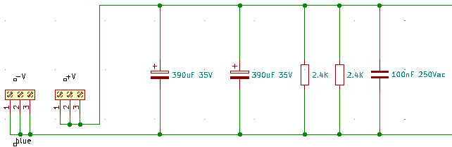 The output circuit is fairly simple, a couple of filter capacitors, bleed resistors and a differential capacitive filter. The size of the electrolytic filter capacitors is dependant on the operating frequency, they are fairly small so I'd imagine it's upwards of 100kHz. I'm pretty sure the supply can output a lot more current, the issue with this is that it creates more ripple in these filter capacitors. The more ripple, the more heat is dissipated in the capacitor and the shorter it's working life.
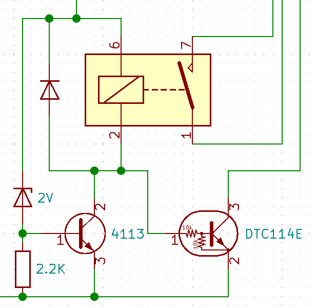
This circuit is for the low voltage output relay. When the output voltage is above a certain amount it will switch on the relay, and when it falls below a certain amount it will switch off. I have got the symbol wrong in the diagram, the relay is normally closed in the off position.
This part of the unit is helpful in telling it's application if the supply has failed or if there is a short circuit in the system. I do know it was installed in a CNC machine, all of the control circuitry is often 24Vdc, so I imagine the supply was replaced due to this fault. From what I've seen so far, my gut feeling tells me it wasn't actually this supply at fault.
The red indicator LED, not shown in this diagram is connected to the biased transistor at the bottom right. When the 4113 transistor is switched on it will pull the base of the biased transistor to zero volts, therefore switching it off, and switching the relay off. When the relay is switched off it will rise the voltage at the base of the biased resistor, switching it on and illuminating the red indicator.
The feedback loop is what keeps the output voltage maintained throughout different load currents. There is a component that looks very much like a transistor, but is in fact a voltage regulator. The PC1093J is known as an adjustable precision shunt regulator. The resistor networks inside the orange circle are what regulate the voltage, the trim potentiometer gives us some adjustment on this voltage. The grounding terminal (K) on the regulator is fed through a voltage divider to an opto-isolator. The isolator gives feedback to the control circuit of whether the output voltage is ok, or it needs more. So when the voltage starts to drop on the output, the voltage drop across the isolators input starts to increase, at some point the threshold is met and the isolator switches on. The control circuit adjusts the duty cycle of the switching circuit depending on how many cycles pass when the output voltage is low. This constant feedback at such high speeds keeps the output regulated. Since the circuit is regulated in this particular way it will actually produce some ripple, it will be shown on a scope later on.
The last part to explain is the control circuit, in the next section I will calculate the design values and compare them to real world results. These types of integrated circuit are always very similar to each other, not a lot changes. For one there is almost always some type of current sensing protection, a feedback circuit and some way of controlling the oscillator frequency of duty cycle limits. These are standard, there are sometimes extra features such as low voltage shut down, high voltage protection, enable, miller clamps, desaturation detection, etc...
Design Calculations
The design calculations I'm interested in are first those associated with the control chip, that is the current sensing, feedback loop and the oscillator. Below is an application diagram taken from the data sheet, it's interesting to see how very similar it is to this unit.
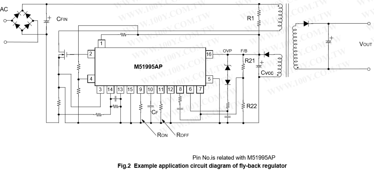
Often most electronics such as these are prototyped first, they never go straight into production. The reason for this is even though design calculations are made they can be a little different from the real world. I'd say that the biggest reason for me to prototype is that the data sheets are often cryptic to read, there is a lot of information, often parts that don't apply to the application. There are so many things to consider when designing a supply such as this, many variables. I'm going to state the order in which I would make design considerations, although this is certainly not concrete.
Many of these supplies are going to have a similar build and will be dual voltage, this means our highest and lowest bus voltages need to calculated. This is anywhere from 283Vdc to 339Vdc (based on 100/120-200/240 input). A core is then needed which steps 280V down to 24V, a frequency is decided on core material and a duty cycle range dependant on the input voltage range. All of these I'm going to reverse engineer from the values provided on the circuit board, I'll then confirm this with an oscilloscope. So first I'm going to start with the oscillator. Here is an extract taken from the data sheet explaining design calculations.
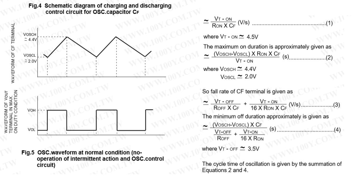
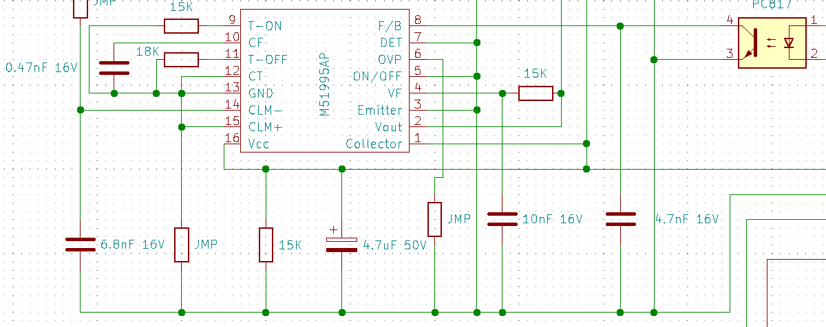
So to explain how this oscillator works it consists of a triangle (saw-tooth) wave oscillator. The wave will start at 2V and switch the output on, when it rises to 4.4V the output switches off and the wave starts falling, when it reaches 2V again the cycle repeats. The on duration depends on Ron and Cf, and the off duration depends on Roff, Ron and Cf. Both of them added together can be used to calculate the frequency. A lot of these calculations given are a little over complicated, especially when many of the values are constants. So first I will make it a little easier to follow, calculations 1 and 3 are not required.
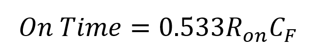
On duration is given by;
Off duration is given by;

I can plug my resistor and capacitor values in to calculate the design frequency and maximum duty cycle. The capacitor is 0.47nF, Ron is 15k and Roff is 18k.
The on time is calculated as 3.75 us
The off time is calculated as 5.29 us
Therefore the frequency should be 110.62 kHz , the maximum duty cycle 41%.
To check this I would connect the oscilloscope probe to the gate of the MOSFET, unfortunately I cannot ground it. Ideally I would use a differential probe, this would allow me to place the ground anywhere in the circuit, the probes are completely isolated from the oscilloscope. Scroll a little further down this page to the oscilloscope readings, I can confirm the frequency was measured at 122kHz. There are tolerances on the resistors and the capacitor, I would say this is a very reasonable result.
The current sensing circuit has two inputs, CLM- and CLM+. The datasheet recommends to use CLM- and that is what has been used in this application. This extract below shows the specification to at which the over current protection will kick in. So when the input sees -200mV between it and ground, the output circuit will shut down for that cycle.

In our application the current sensing resistor is 0.24 ohms which means that for every 1A of current that passes, 0.24V will be across it. There is a resistor network that alters this value by a very small amount, this allows a very accurate trim of the current. In all honesty, looking at this design the trim potentiometer is going to do very little. The design should limit the current to 0.83A.
Load Testing
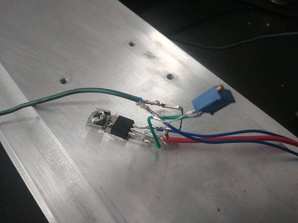
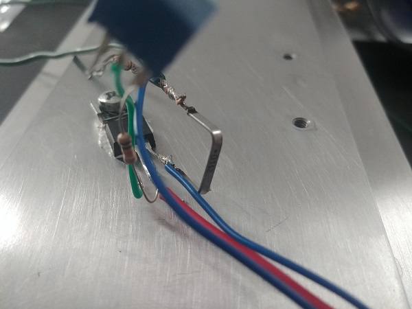
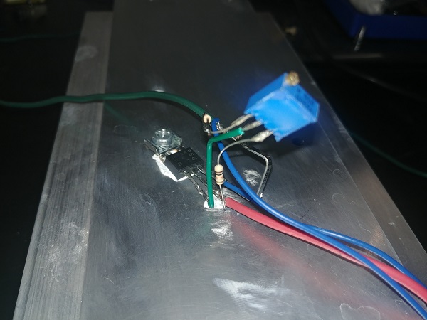
The final task is to load the power supply at it's maximum rating, and then exceed it to ensure it protects itself. At the time of writing this page I had not yet but an official unit for load testing. Instead I quickly threw something together with an IRF540 MOSFET and a 20 turn trim potentiometer. The idea is to bias the MOSFET gate to turn it partially on, the gate voltage will determine the current flowing through the MOSFET. The data sheet says the maximum power it can dissipate is 150W, more than the 100W power supply. I used a very hefty heat sink in order to dissipate the heat with thermal paste in between.
I unfortunately did not have any way of measuring the current directly, I should invest in an ammeter. I used a shunt in a Kelvin configuration to get the best measurement, the resistance a little too low for my liking. 0.01 ohm means 10mV for every amp.
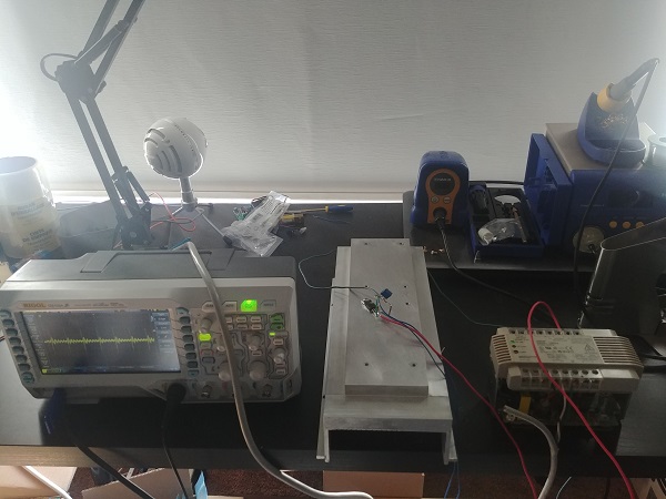
I had to use the oscilloscope in order to get somewhat of an accurate reading. There was quite a lot of noise present, a should have put a quick filter together, regardless I got some measurements.
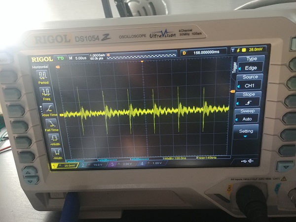
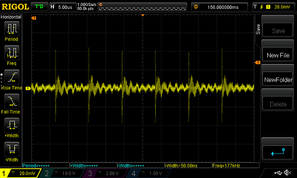
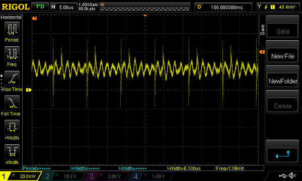
I use a digital oscilloscope due to the fact I can save my traces, it has really been handy. The first trace shows no load through the MOSFET, the scope set at 20mV per division, 2A per division. The second trace is a modest 2A, almost half the capacity of the supply. The large voltage spikes are caused from the switching circuit, the space between them is the operating frequency.
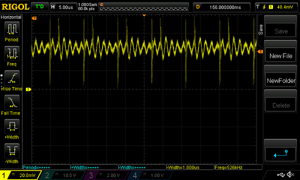
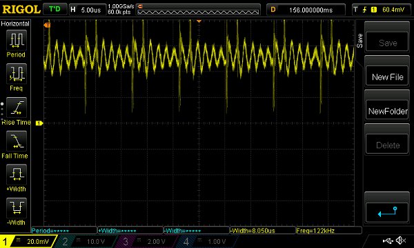
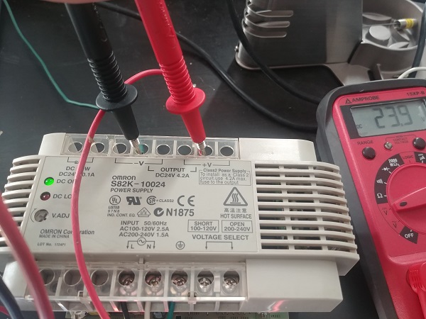
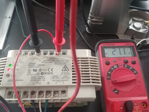
The third trace is the maximum rated current, 4.2A at 100W. At full load I checked the voltage at 23.9V, this supply is very stable. The third trace is increasing the current further which causes the output voltage to drop, once it hits 21V the low voltage light illuminates. The most power I managed to pull from the supply was 110W, the biased MOSFET stood up really well.
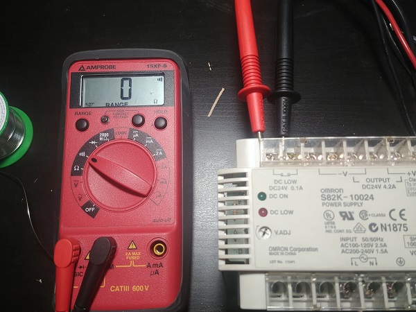
The left picture shows the supply at full load, it fluctuated between 23.8 and 23.9V. The second picture shows the supply overloaded, this causes the voltage to drop, it doesn't shutdown however. The relay switches off and the contacts close, the "DC Low" indicator illuminates.
Conclusion
Overall the project was a success in that I have a working unit. I tested all the vital components and I'm confident it has lots of life left in it. I'm also disappointed in that there were no obvious signs that it had failed. The unit was in a very dirty condition will a lot of metallic dust present. I can only assume that if it was not working then the clean may have fixed the issue, the fact that nothing was damaged because of this would be highly unlikely.
I will also add that there was a lot more testing and theory I wanted to add to this page. I unfortunately do not (at the time of writing this) have a differential probe for my oscilloscope, so I can't go into more details on the measurements. I will add that when I do invest in a probe that I will likely revisit the project if I still have the supply.
Update: I chose to give a demonstration of why oscilloscopes are dangerous if not used properly, due to earthing. So the earth on a probe, is connected to the chassis and the supply earth, which in the end connects to neutral. Often the earth probe will be connected in circuit, which is very bad if not isolated from the supply live or neutral. So for this supply the earth probe cannot be connected anywhere on the input side of the switching transformer, only on the output side since it's isolated. I demonstrate with an earth cable what happens. So ultimately I blew up the supply, this gives an opportunity to actually fix it.
Hello, if you have enjoyed reading this project, have taken an interest in another or want me to progress one further then please consider donating or even sponsoring a small amount every month, for more information on why you may like to help me out then follow the sponsor link to the left. Otherwise you can donate any amount with the link below, thank you!