Precision Hydraulic Forging Press - Page 3
This is the third page into building my precision hydraulic forging press. The unit has completed the prototyping stage and worked perfectly. The unit is now in the second revision and is nearing completion with just the control electronics left.
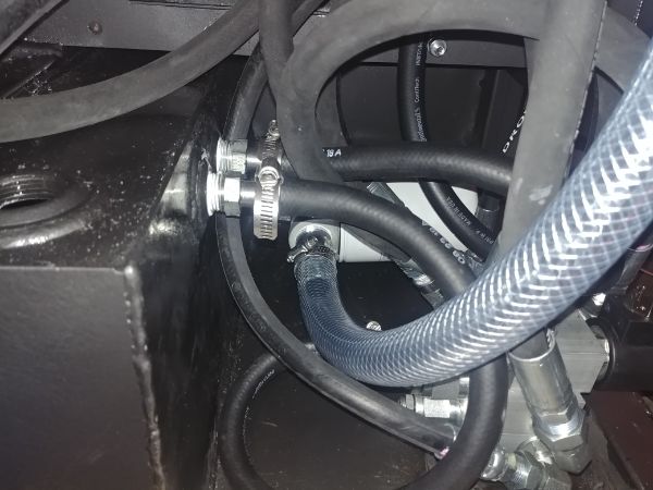
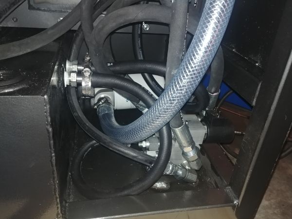
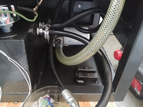
I got some hose for the return lines. I heated it up and installed them the best I could, the hose barbs were never meant for this hose and were turned on a lathe. Of course in the future I will use the correct connections, but these will work for now.
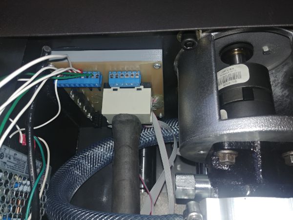
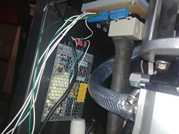
I bonded both the control board and power supply in place with RTV. I would have used board stands but for my own personal use it does not matter.
I finally got a grease gun as I needed one for another project. I made sure to get a high pressure one for this press, stated as 7000psi. I injected some grease into the bushes, once filled it took a lot of strength to get it to extrude, these clearances are very small.
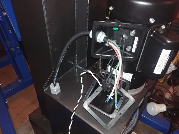
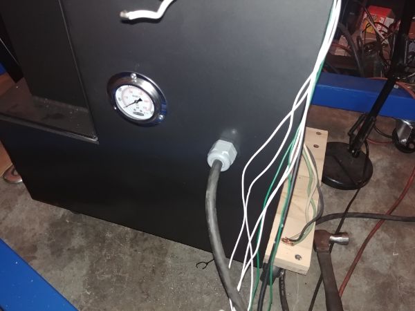
I drilled a hole in the top to pass the motor power wire into the main unit. I also drilled a hole in the side for the power supply cable. I am wondering if I should place some kind of shielding over the cable as it is intended for a harsh workshop environment.
The press is in excellent working order apart from the back cover is left to paint. I put the project on hold for a little bit since I have been rebuilding a CNC mill. The mill will be used to make parts for this press, so I will be doing another design revision.
The design revision is that all of the box frame will be milled to exact size, it will also be welded together using fixtures and a TIG welder. That will ensure that all of the frames are exactly the same, it also ensures everything will align correctly. Secondly all of the sheet will still be cut again on plasma but instead will be riveted together with angle iron. The angle iron again will be milled to the correct dimensions and be TIG welded together at the edges. The oil tank will be a separate part to the frame, it will be completely welded and bolted in place. The valve body will be a single unit utilising a manifold. There will only be a couple of hoses to connect the tank and the hydraulic cylinder.
I believe this will be the final design revision and should reduce all potential leaks or failures. I also need to get the unit CSA approved which means I need to provide a lot of design paperwork to get the labels. There will be a few design updates on the electrical system and the foot pedals, partly because my hard drive failed and these couple of files were not backed up.
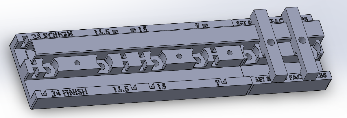
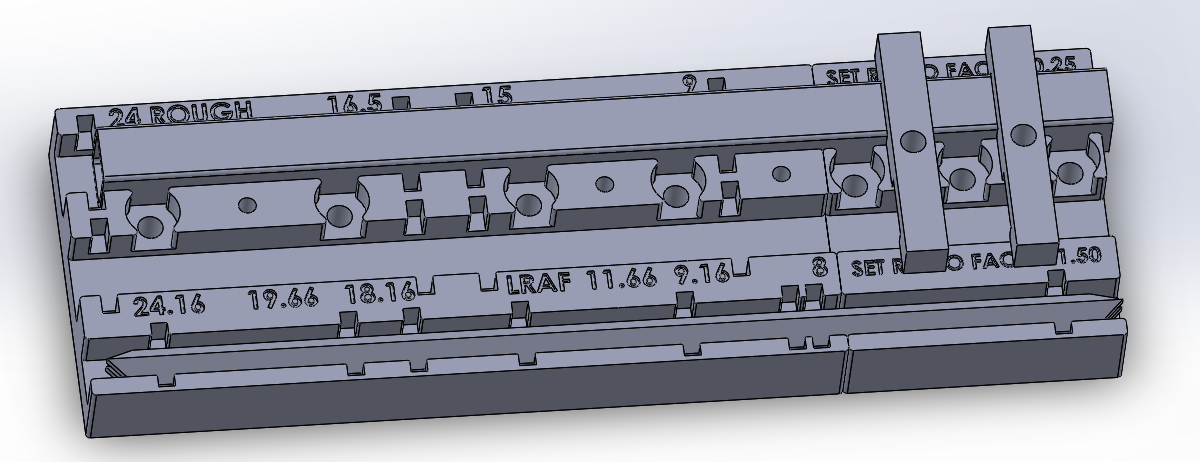
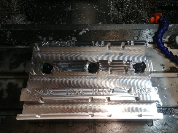
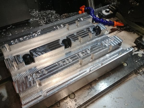
I have started designing a lot of fixtures that will aid in the machining, the very first one is to quickly cut the tubes in the frame accurately to length. The cutting tolerance from the supplier is 0.25 inch, I want them within 0.010". The fixture below is designed for all of the lengths and can quickly be bolted to my milling machine, or rather set in place and remembered as a specific work offset. As a reference for the size of this thing the tube is 24 inches long. I will be making a similar jig for all lengths of angle iron on the edges of the machine, including holes for the rivets.
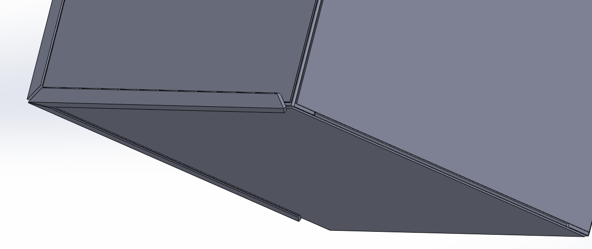
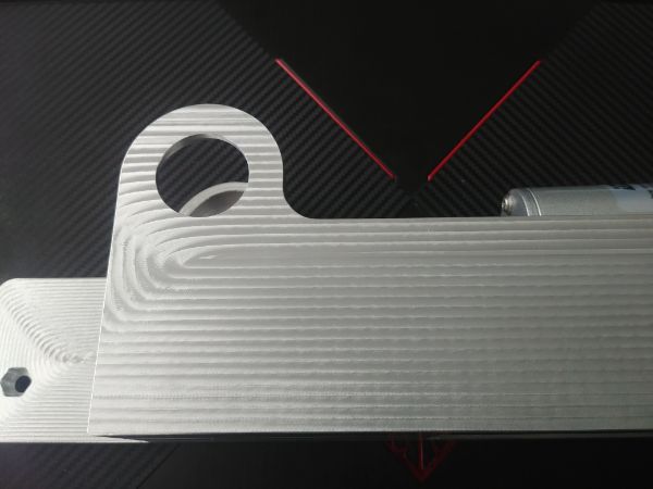
I started from scratch on a new design for the press, this time taking into consideration the tolerance of the stock. Here is a close up of the edge of the frame. To the inside is the box-section, then the sheet panels and then some angle-iron on the outside. The key here was to make the sheets undersize so they would assemble properly, there is a large radius on the inside of the angle-iron which would stop it from assembling properly.

The way I will be milling the ends of the angle-iron automatically leaves a chamfer, this is how they meet. I will be TIG welding these parts on the outside as to make them prettier. The chamfer ensures I can get a full penetration weld.

Here is another picture showing that the panels are undersize, these will be held together with rivets on the outside and a couple of tack welds on the inside. Overall it will still be strong but won't require any grinding, that is very important in terms of the mess it makes.
Here is the progress so far, this is a complete solid unit. Everything here has been cut accurately to size by either a CNC mill or a CNC plasma cutter. I still need to add the rivets and finish off two of the access panels.
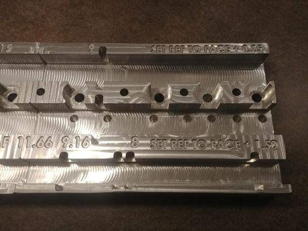
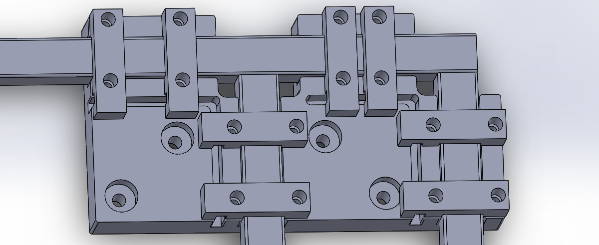
I updated my milling fixture with the additions of all sizes of angle-iron for the above design. It also turned out that to buy a larger size of aluminium was a lot cheaper that the less common size I was originally looking at. I did not include the clamping system for the angle-iron as this will be separate to this fixture. I hope I can get machining this in the next day or two.
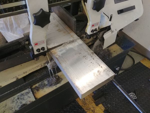
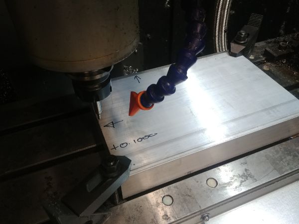
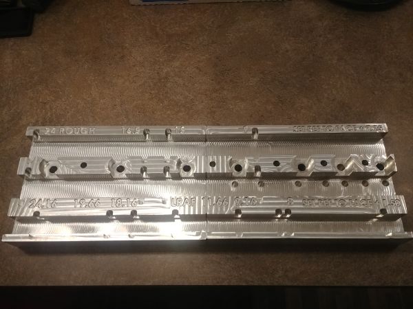
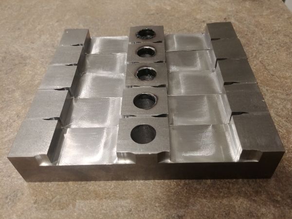
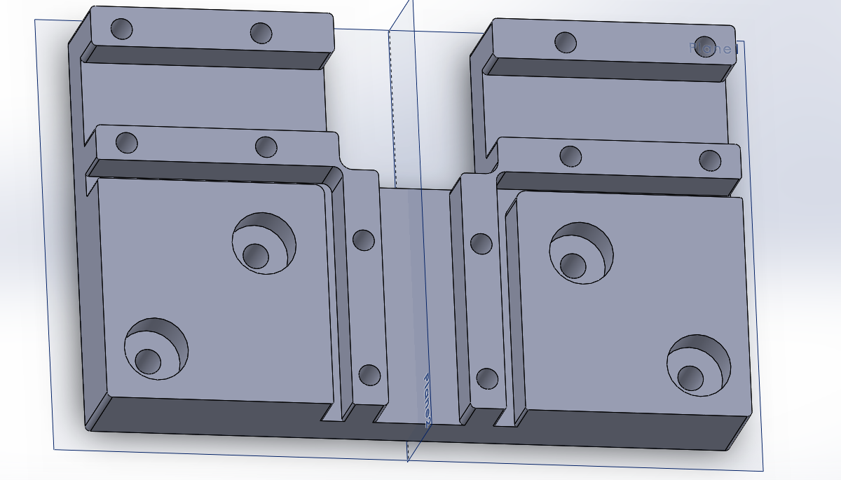
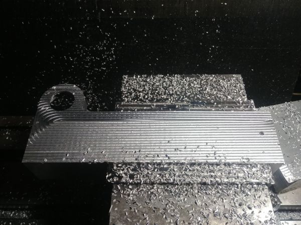
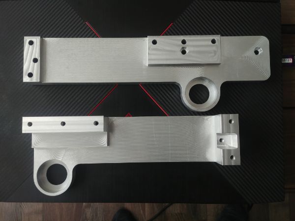
I did a quick little update to the above design because of the limitations of the milling machine I will use. The two parts were merged together and then split exactly in half. I bought a large piece of aluminium and cut it to size, it was placed in the mill and clocked true.
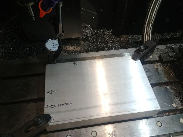
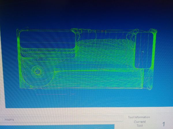
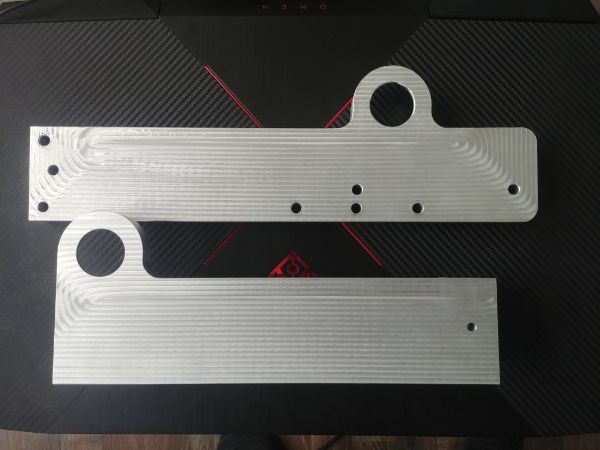
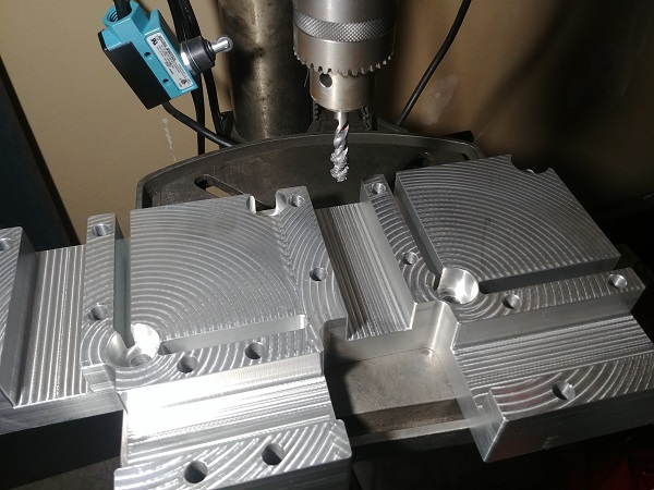
I created a tool path to mill out a pocket and drill a couple of holes.
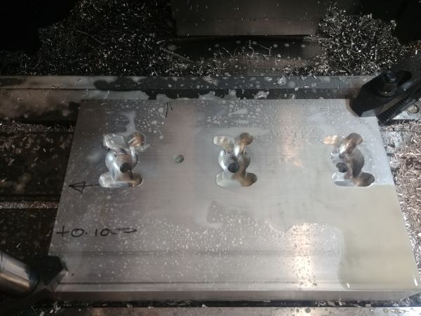
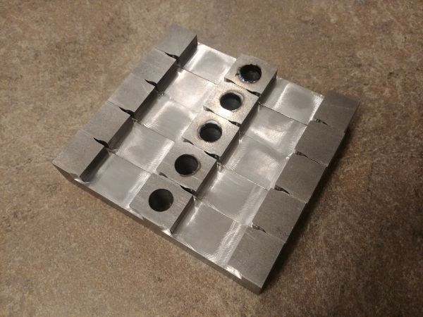
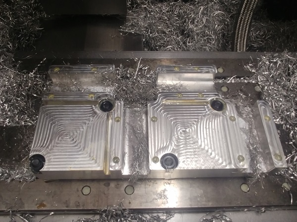
The holes are what will be used to clamp the whole fixture to the mill, they also worked for milling the fixture too. The part came out really good despite rushing to get the second operation started within an hour, it was my lunch break.

The day after I was rushing again to get this part done in my lunch break. I unfortunately made a mistake, I forgot to save the changes of the work setting coordinates. So there are a series of holes that should not be there, thankfully no harm done. Once the first operation was done the second operation took around 2 hours to complete. I was using a coated carbide cutter and left the machine unattended so I was very conservative on the speeds and feeds. I do believe I could get this part to just 30 minutes, maybe even less.
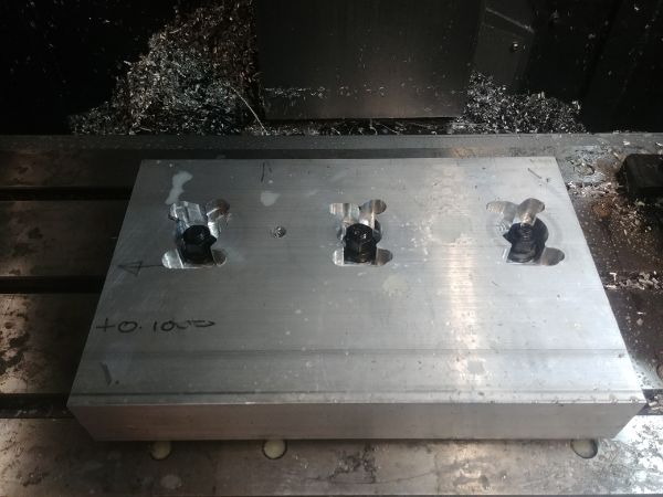
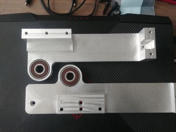
These are some of the clamps, they are in 1018 steel. These I managed to machine in about 3 minutes each, I was in a bit of a rush. I chose to mill out the holes in the middle, however the milling cutter was not long enough causing some heating.
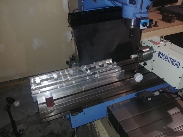
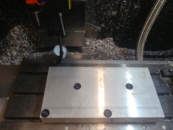
This is where the fixture will be bolted to my milling machine, semi-permanently. The bed on my machine is 48 inches long and the travel is about 40. There are still a number of fixtures to make, the fourth axis is something I may get out of using. There is a single part that requires it, but only for drilling some holes, so maybe I can make something smaller to index manually.
I have been busy designing more fixtures, this time for welding. There are a couple of corner vices out there but all of them seem to be of the same construction, I know from experience that they are garbage. This design may seem to be a bit overkill but it ensures the welds won't make it warp and everything gets perfectly aligned.
I also made this fixture for a tee joint, I'll make just one of these as it will quickly get expensive.
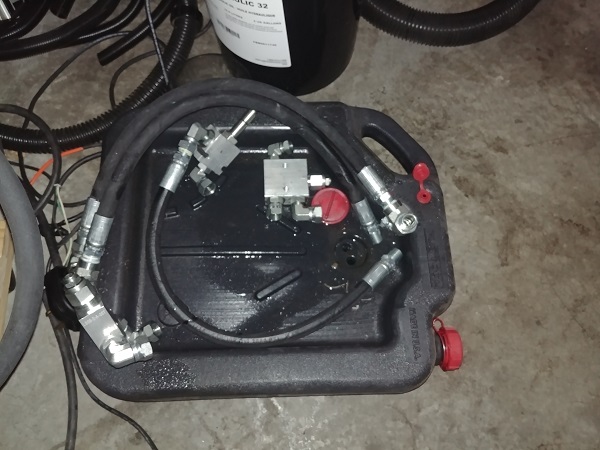
On a separate note I have started looking into a better solution for the hydraulic system. I know how to connect them and how they work, but I lack the knowledge of what products are out there. The system I have works but is a mess of hoses and connectors, definitely something I do not want in the final product. I have been looking into the valves I already have, they are the cartridge type. I have started designing a manifold that will utilise parts of what I already have, the only issue is making it without multiple tool setups is impossible. I have made the decision to reach out to hydraulic suppliers of a better solution. I don't doubt it will cost more money, but for the benefit of simplicity and reliability it will be worth it.
I did one last revision to the welding fixtures, this one will ensure that some of the spacing is perfect.
Bad news! I am now no longer able to use the milling machine at work, but I knew this day would come eventually. I bought a long length of aluminium, cut it down into four lengths, drilled the mounting holes to suit the t-slots on the bed. I managed to almost finish one of the jigs before everyone got banned from using the machines. It used to be encouraged, but my workplace has been going south for a while, this is one of the many changes. I just wish I had been told maybe a day sooner.
This means I still have a little bit of work left to finish on this fixture. The big problem is that the t-slots are different on my mill than the one at work, so I will have to drill some more mounting holes. The biggest difference is that I do not want to use coolant, and dry milling aluminium is not a wise idea. Luckily I managed to find a micro-mister that should do the trick, the blast of air may work better for chip evacuation. I purchased a small silent compressor to run it. I know that kerosene is the best lubricant for machining aluminium, but I don't want headache, so I opted for some extra virgin olive oil, healthy!
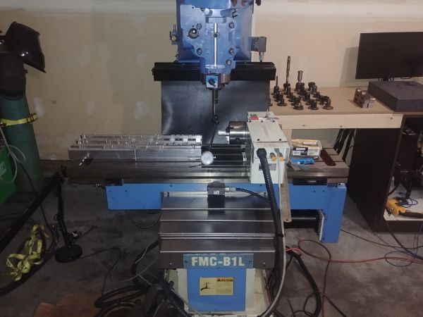
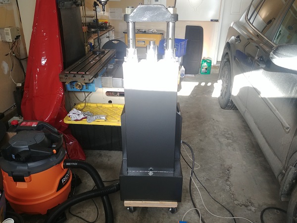
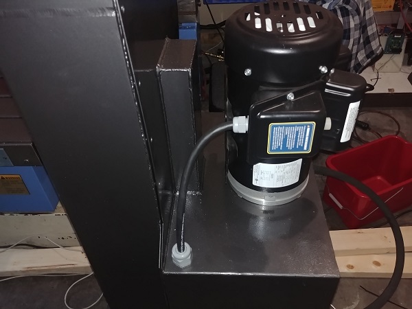
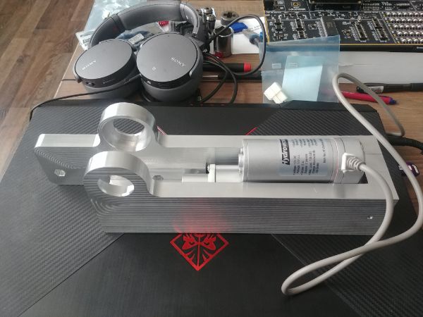
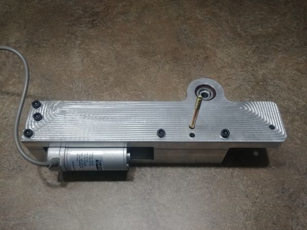
I shouldn't spend too much time machining the jigs on this page, that will be another project in its own. Here is the press at its current state, from the front it looks complete, apart from the foot pedal.
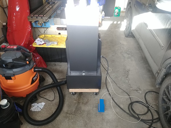
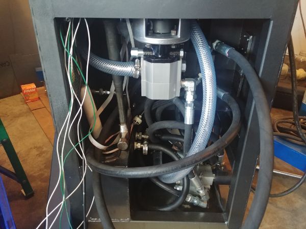
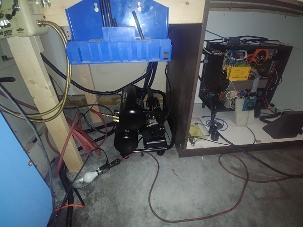
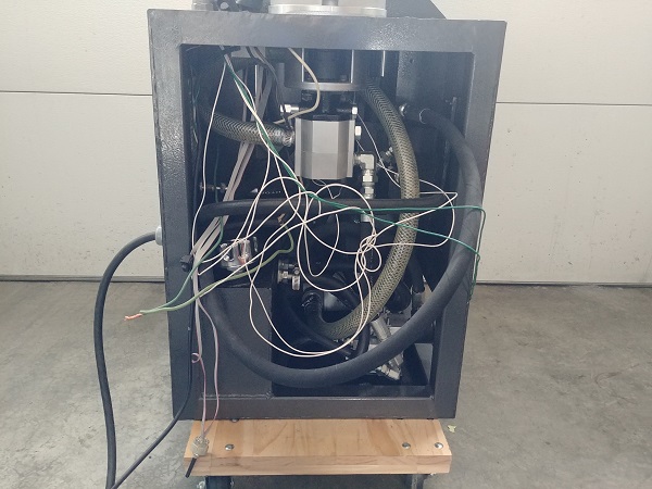
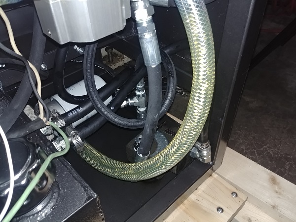
Here is one of the pictures I missed out, that is the cable from the motor to inside of the unit, maybe I should use a conduit of some sort. Inside of the press looks a lot more unfinished and generally just messy, I always said I was not happy with it.
The first thing was to remove the original valve work, it's complicated, hard to work on and all of the connections are something else to fail.
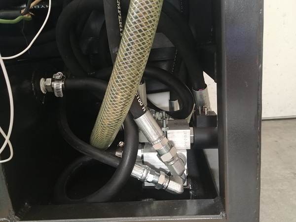
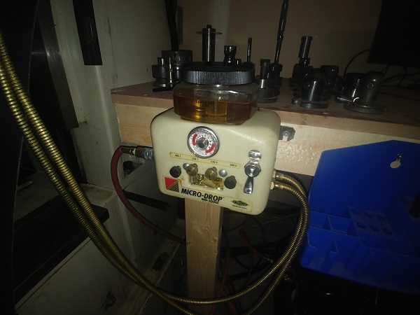
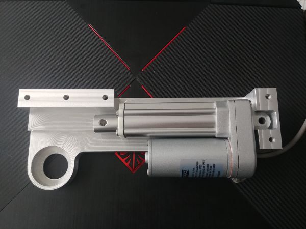
Originally it used a valve to bypass the pressure through a relief valve, that would kick the pump into slow operation, it would also causing heating in the system due to the restriction. The better option is to use a pressure compensated constant flow control valve, ideally an electronic one. I chose to go with a manual one since they are a third of the price, I can modify it to be electric myself with a servo. This valve will allow any flow I like to the hydraulic cylinder to control the speed while the extra flow is diverted back into the tank. The whole system will only see the same pressure as the hydraulic ram, this means less power consumption, less heat generated and a longer service life. It also has a built in pressure relief valve which is adjustable.
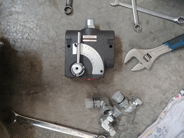
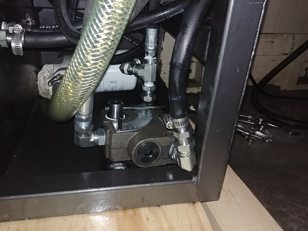
The valve was really easy to install and looks a lot more cleaner. I tested the operation to find I can control the flow while it is moving fluid, that means I can easily control the speed of the hydraulic ram when it is running, a variable foot pedal. I adjusted the pressure relief valve to 3000 psi, that is 53,000 lbs / 24 tonne of crushing force, and a little bit less pulling force.
Since I have changed the system I will need to update the control board. I will source a foot pedal that has a potentiometer so I can control the speed of the ram, two pedals for each direction of stroke. I need to build some kind of a servo to control the flow valve, or maybe I can buy one. On a separate note the manufacturing jigs are nearing completion and so is the final design of the project.
It's been about a month since my last update and I have got a lot done. I first started to reach out to suppliers of mainly the hydraulic cylinder, the electric motor and the control valves. Overall this proved to be a huge waste of time, no one seems to be interested in supplying low quantities or even replying back to me. All of this got me thinking and I decided that the most important part of the press, the hydraulic cylinder, will be made from scratch. I have no problem sourcing the valves, hoses and the motor, I just wanted a better price on larger quantities.
Another really expensive part of the press would be the hydraulic flow control, so I spent a lot of time designing a servo. It is still cheaper for me to build a servo for the valve than to buy an electronic one. There are some benefits to having a separate servo in that worn out parts would be much easier to replace than a whole new valve assembly. I have made sure that the wearing parts are relatively cheap and fairly easy to replace.
In making the hydraulic cylinder myself I can greatly improve the rigidity of the overall press. The bushes will wear less, the seals will be better quality, the safety factors far exceed the original and it is all sourced in Canada. I have increased the capacity of the hydraulic oil tank and included some vents that will cool the oil. I have greatly reduced the amount of welding required, most of that will be TIG welded, there is now very very little that requires MIG welding.
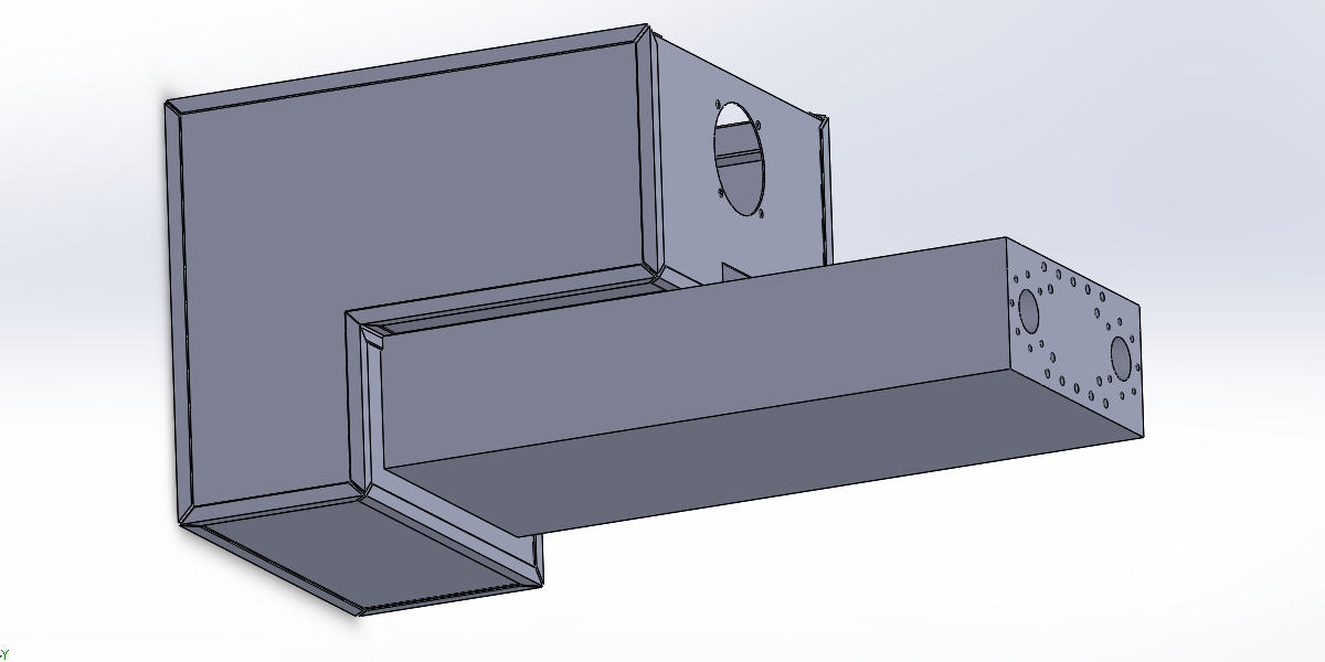
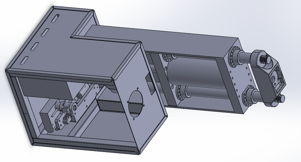
Here is an updated view of the design. The vents on the side circulate air through the oil tank to the back of the unit, it is a sealed system. The top and bottom casting have been beefed up which simplifies the mould slightly, more importantly it helps rigidity of connection to the hydraulic ram. The top and bottom of the hydraulic cylinder are integrated into the frame which vastly improves rigidity and stops any twisting. Both the top and bottom have bronze sleeves to reduce wear and have a serviceable part. Between the top and bottom have high tensile tie rods to hold the assembly apart. The hydraulic tube is thicker than the average cylinder which increases safety factors and rigidity. This setup is far superior in build to the previous but is at the same price.
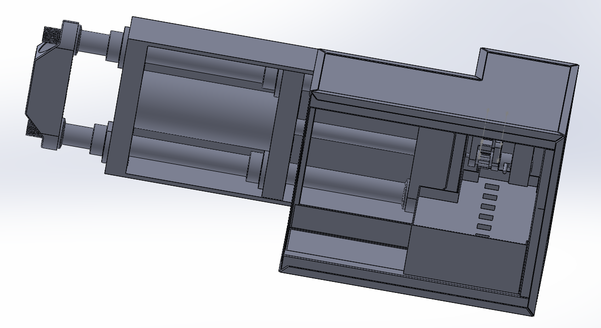
Here shows a better view of the hydraulic oil tank, with an inside panel removed. Air will be pulled in from the back of the unit and passed into a baffle, the air has to circulate in a "U" shaped flow that should remove as much heat as possible. The lower I can keep the temperature in general the longer the life of the oil.
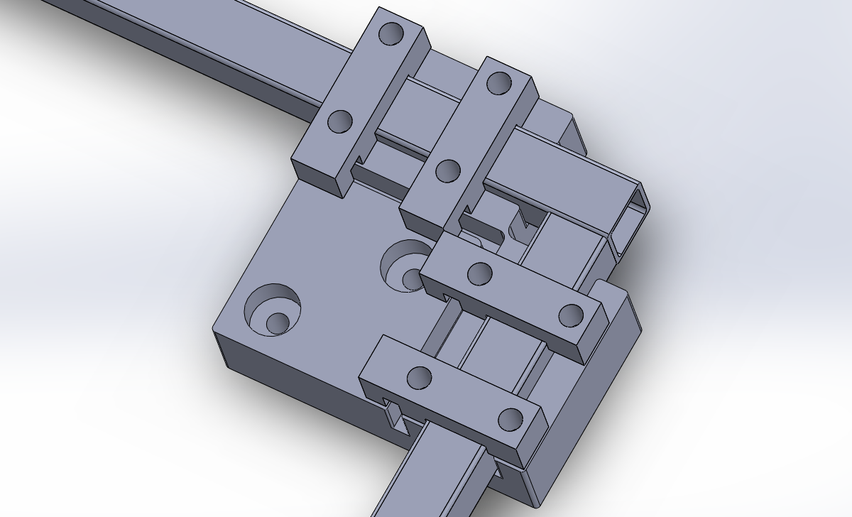
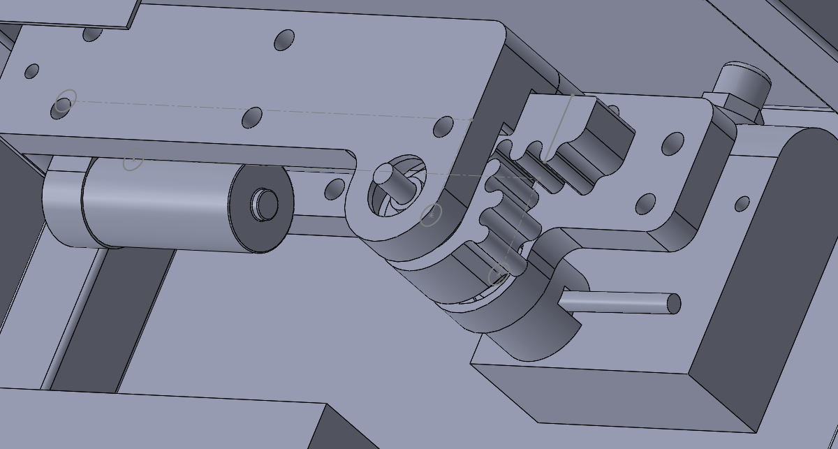
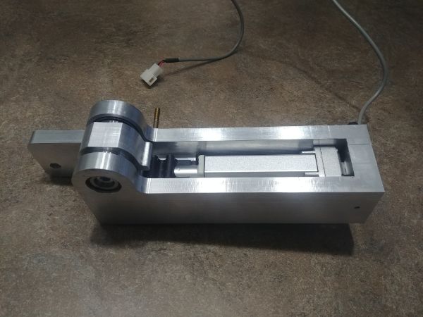
Here is a close up of the servo, there are still a number of components missing here but this will accurately position the valve. The bearings and the position sensor should last a lifetime since they're rated at high duties. The pinion is made from aluminium and the rack from a molybdenum filled nylon which has superior wear characteristics. The servo is easy to service if parts wear out and the parts themselves are fairly cheap.
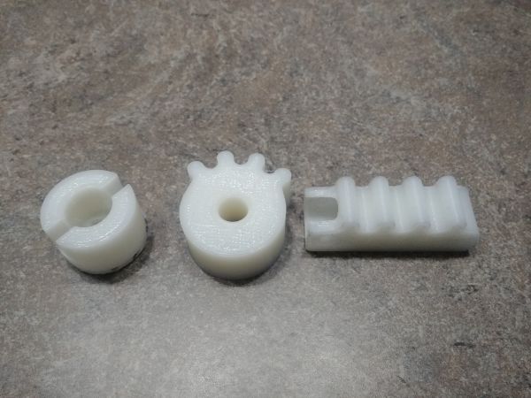
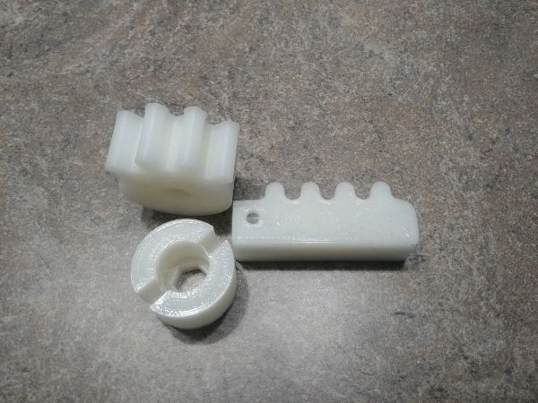
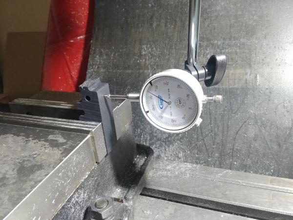
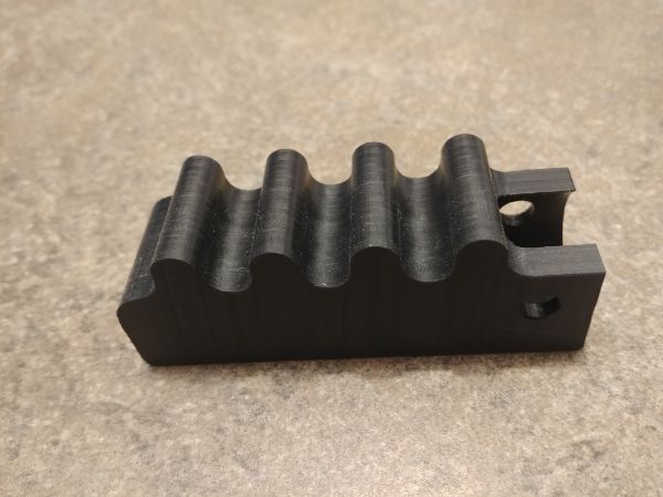
I first started out by 3D printing some of the parts to see how they would fit together, they didn't. I knew the tolerances would be hard to meet and the 3D printer clearly couldn't meet them, even if I cheated some sizes. Although the part with the notch through it can be used as this one just met the tolerance.
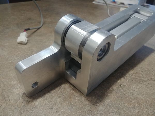
I then started some machining of the frame.
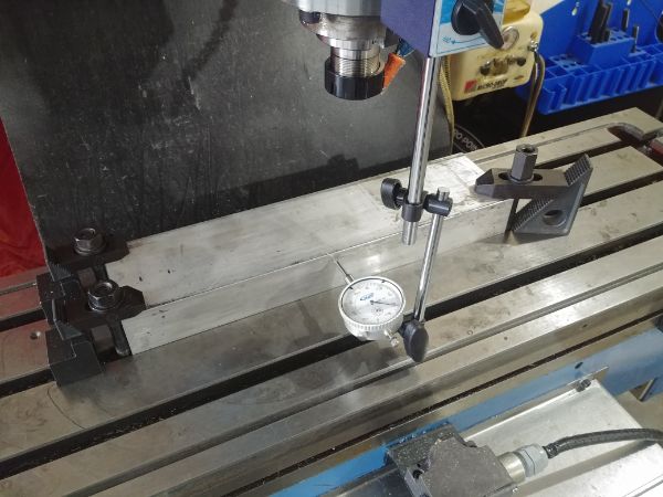
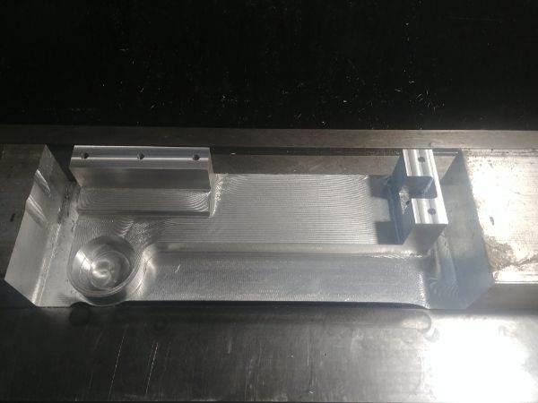
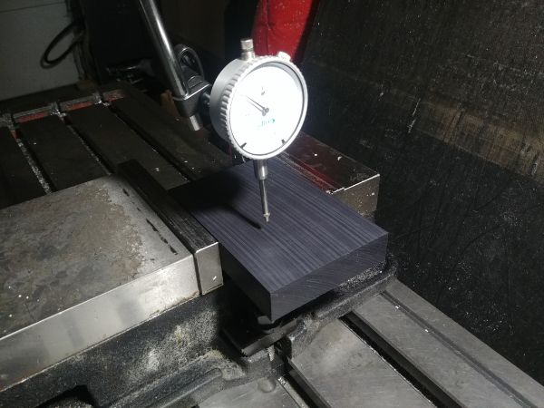
It came out pretty good and I learnt what tolerances my machine was capable of, a lot better than I expected.
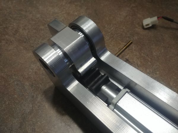
I had to take a lot of care machining the rack in keeping it to two operations. The rack was attached to the actuator using a PEEK pin, this will stay in place due to the design, but I did have to press it into place.
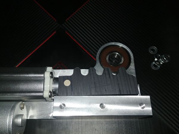
This is the current revision of the servo, it has a revised pinion gear and shaft that connects to the valve itself. The servo does actuate as it should but still requires some modifications to meet my new design. The potentiometer that measures its position is rated for millions of cycles, the extra modifications will connect it to the frame.
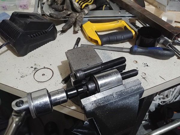
I am really happy with the current progress of this servo. I currently have the revised versions being made on my milling machine and will later make the modifications to this one so I can attach it to my prototype press. I have started work on the electronics and believe I have sourced all the required components. I got some industrial pedals that are originally intended for electric forklifts, these are perfect for my application. On a separate note I have been working on the welding jigs a little more. I got a used drill press so I could thread the holes in the welding jig. I modified the drill so I could use two pedals to spin it forward or backwards. I gave it a quick test with a piece of tube and it works just perfect.
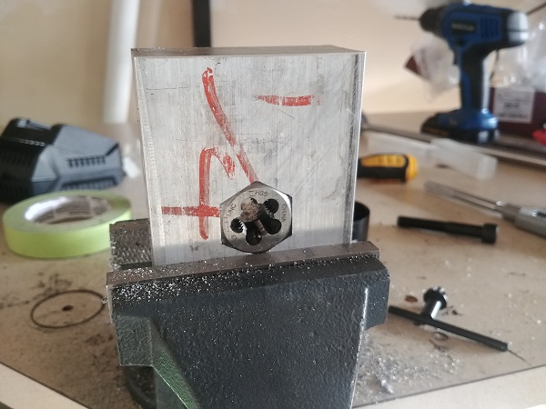
The one thing that is taking me a lot of time is threading the bolts to the end. The biggest problem was actually holding the die which I solved by milling a pocket in some aluminium and pressing it in place. I still have quite a number of bolts left to do but it is now easier, unfortunately they still all have to be done by hand as I have nothing powerful enough to turn them.
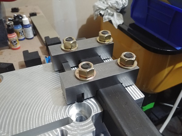
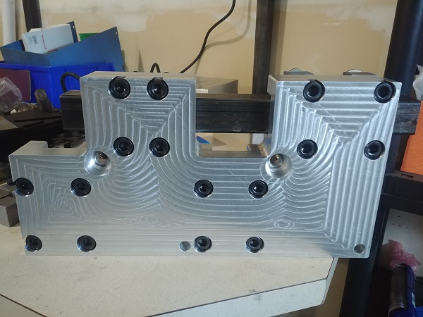
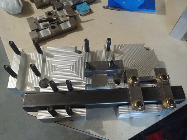
This is one of the welding jigs complete, this will save me a tremendous amount of time on the welding, it will also ensure each frame is exactly the same and perfect.
I still have lots and lots to finish on the whole project. There were some parts that I simply could not make without the use of a large lathe. I made the decision to buy a small lathe and make special fixtures so I can do much larger capacities. The biggest problem originally was turning and threading the columns since they're about 40 inches long. The distance between centres on my lathe is about 26 inches. If I remove the tail stock and make a sub-spindle then I should have no issues. There are other things such as the hydraulic cylinder tubes, making the threading automatically disengage and some other simple modifications.
Keep checking for updates, this is my current project.
Hello, if you have enjoyed reading this project, have taken an interest in another or want me to progress one further then please consider donating or even sponsoring a small amount every month, for more information on why you may like to help me out then follow the sponsor link to the left. Otherwise you can donate any amount with the link below, thank you!