CNC Milling Machine - Page 3 - September 2020
This is the third page in rebuilding and updating my new CNC milling machine.
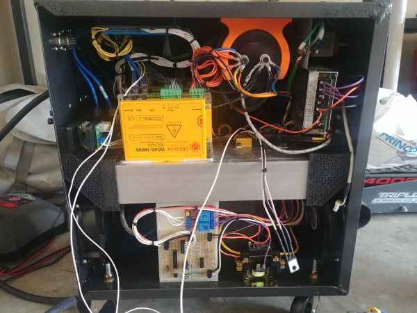
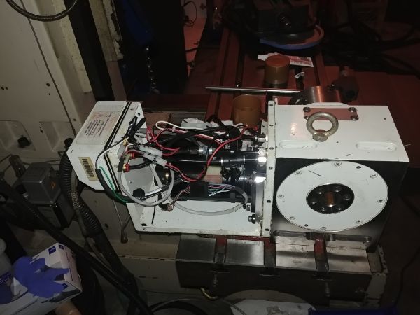
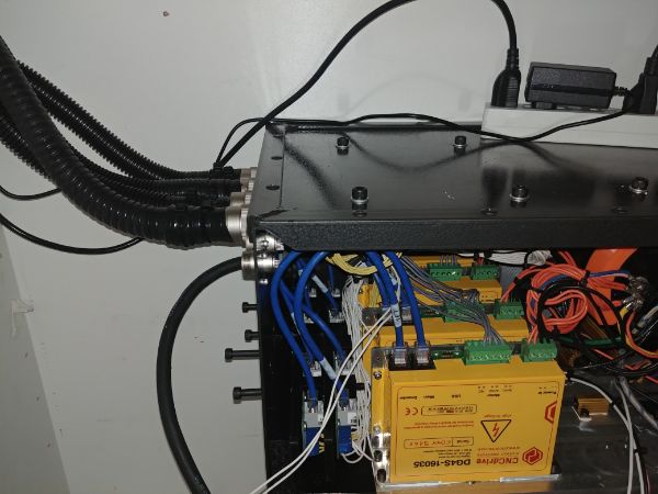
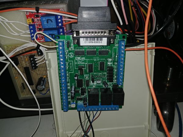
I am getting super close with the control unit. Three of the drives are installed, all of the control wires and all of the power wires. I need to add another drive, the dynamic braking circuit and just one more control board.
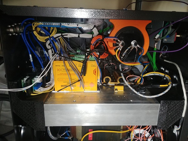
Next on the list is to build a dynamic braking board. When a servo spins up it draws power from the supply whereas when it decelerates it acts like a generator and pumps power back into the supply. The bus voltage in this system is 120V DC and the maximum voltage for the drives is 160V DC. The dynamic braking circuit is to limit the bus voltage from reaching 160V DC. So I need to build a circuit that will "crowbar" the supply when it reaches 150V DC. I must also add some hysteresis into the design as I don't want the switching circuit to act like an oscillator. When the threshold of 150V is hit it will drain the supply until it hits a voltage of around 130V, then it will shut off.
I went overkill with my braking resistors as I wasn't sure how fast I would be running the mill. The faster the movement of the mill, the more power I will pump back into the supply. Having such a large filter capacitor also helps to absorb some of this power and makes exceeding the limit a little harder. I was going to draw up a circuit diagram and make a board from scratch, but this will never be seen again, so here is the result.
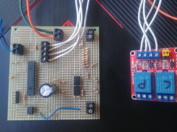
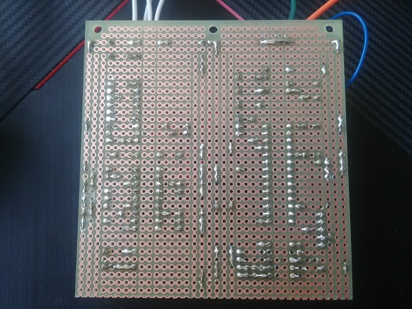
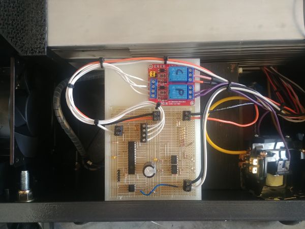
I instead chose to go with strip-board to save some time. The circuit has a large potential divider that reduces the bus voltage down 100 times. There are then two comparators, one set at 1.30V and the other 1.50V. A micro controller determines when to switch on a transistor that discharges the bus through a resistor. Also on the board is a control circuit that charges up the filter capacitor before connecting the supply. In all this board ensures the supply does not start until the control is ready for it.
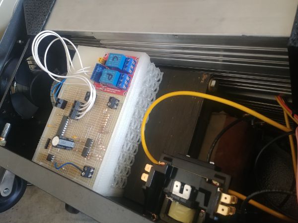
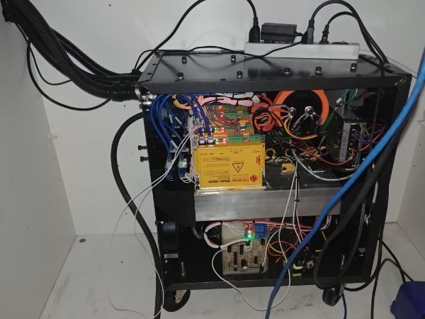
In the mean time I designed a mount to hold this board in the unit.
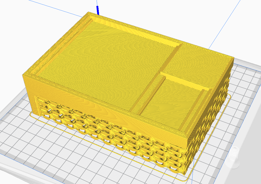
I left the build support in place as it would cause the cooling air to travel over the top of the transformer, I secured it with two bolts underneath.
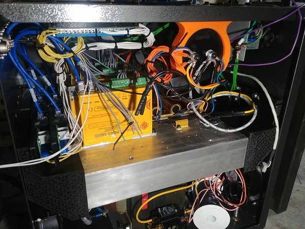
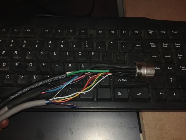
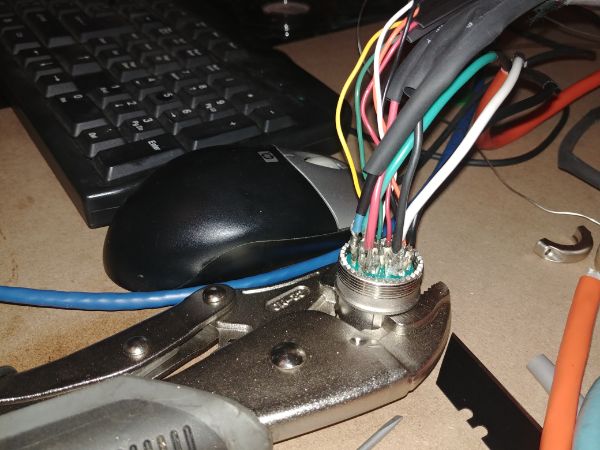
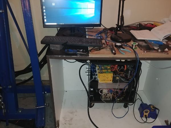
The electronics are almost done, in the mean time I wired a servo to a connector in order to test the software side of things.
I was happy that the servo functioned as it should, so I wired the rest of them. That is the X, Y, Z and A servo's including the homing switches.
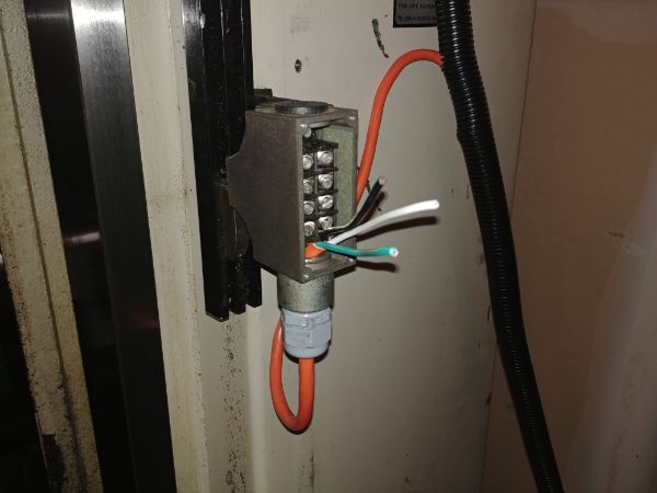
The A-axis was a little different as it used a slightly different encoder, it also has some control electronics for the pneumatic brake.
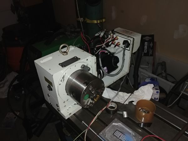
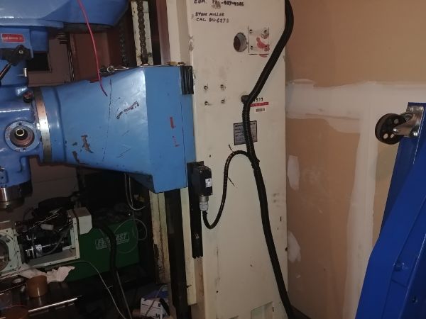
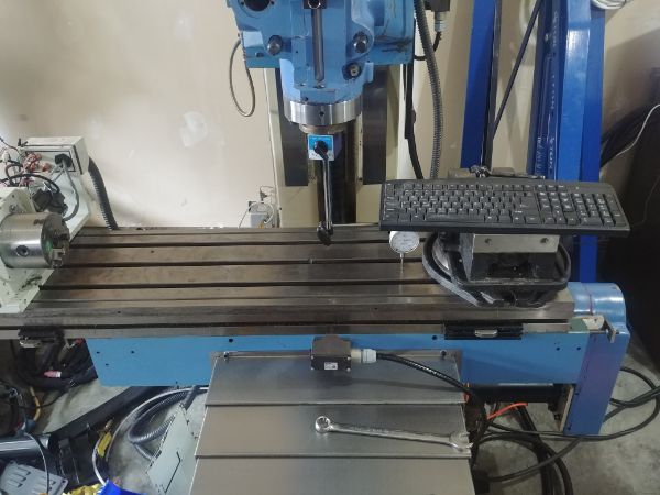
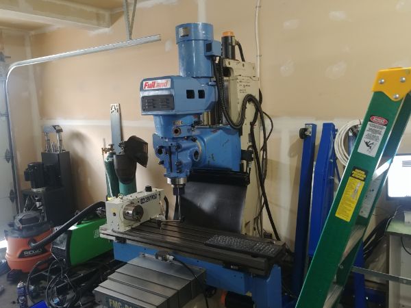
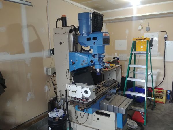
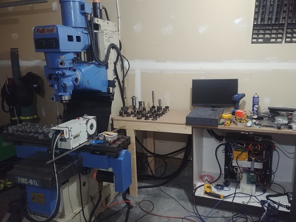
Here is the current setup, that is all servo's move and home.
It has been a busy day and I certainly did not take as many pictures as I should have. The original design for the dynamic braking circuit was isolated from the control as I figured the servo's would be noisy. I made an original circuit that had this to find my isolated DC to DC converter did not output an accurate voltage, 5.5V as opposed to 5V. That in itself would increase the thresholds by 10% and therefore be no good. I also found that a number of old components I bought a while back did not work, thankfully they were not my usual supplier, I did not show that board because it was a complete failure.
So I did a second revision of the dynamic braking board as you saw earlier, the problem is that the logic ground is the same as the drive ground. I quickly found that the noise would cause the micro controller to reset. I also found that the dynamic braking was not at all needed, the servos pumped nothing back into the bus. I disconnected the dynamic braking circuit and the system worked perfectly. The board is still there as it uses the dynamic braking resistors to charge the bus capacitor before connecting the main supply. If I was to add a second 5V power supply and a couple of isolators then I could add the braking circuit back in, but honestly I don't think it will ever kick in with these results.
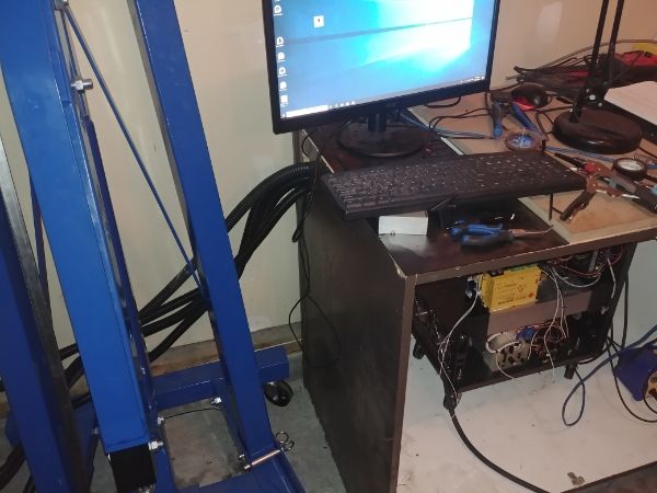
The software took a little bit of working out as it uses a plugin for the ethernet control board. It actually turned out to be easy and I had the servos moving in no time. I now have all of the axis's moving in the correct direction and homing correctly. The servos are however a little noisy and erratic on standby. I will have to connect the programmer and change some of the feedback settings as they're trying far too hard to pin-point their position.
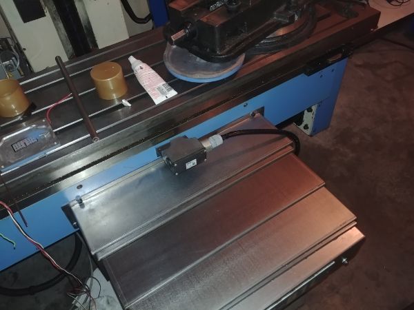
I got the lubrication system working to find one of the lines had broken, I'm not sure how it happened but it must have been in the move. I got that fixed and left it running for a while to fill all of the lines. The pump itself is a mechanical one that constantly runs raising a plunger very slowly. After 15 minutes the plunger reaches the top and then dispenses some oil, it repeats the process. There is no way of changing this time without changing gears, so it's a basic system. I then found while playing with the X-axis movement that the copper line I installed was in the way, it got chewed up. I will replace the line before moving any more axis's, I will ensure I put it in the correct place this time.
I have the hand wheel encoder to wire, the lubricator, tool height probe and the spindle control system. After that I will concentrate on tuning the servos and then make some slide way covers before I machine anything. I think the build is progressing nicely, it is taking longer than expected but it's worth getting right.
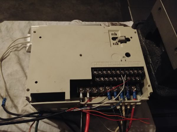
I fixed the oil line and made sure to route it correctly. I then set to wiring up the spindle motor and control. The control board outputs a 0 to 10V signal depending on the speed of the motor, that initially worked, well for 2 minutes. The board then output a constant 10V which tells the mill to run at top speed. I then started playing with the inputs to find the the VFD is setup for three speed ranges. To top it off the VFD does not have a parameter module so I cannot tune it. So overall I can get the spindle to spin in either direction, but I'm not all that certain of the speed. The bottom motor bearing also started to squeal at high speed. I removed the spindle motor and pulled both of the bearings, they had clearly leaked grease. I replaced them with new bearings as they had metal seals, these are difficult to remove without damaging, so a re-grease was out of the question.
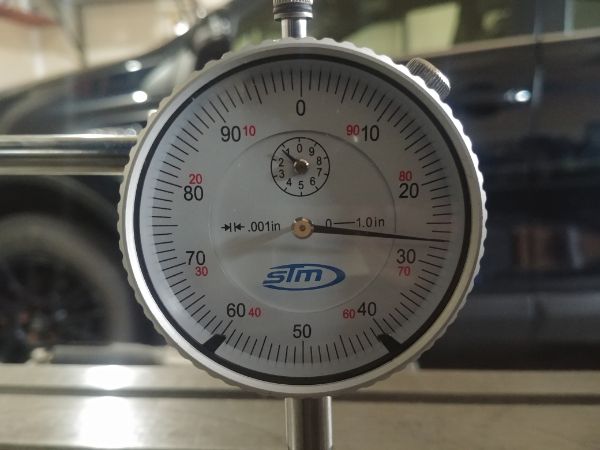
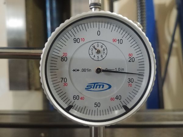
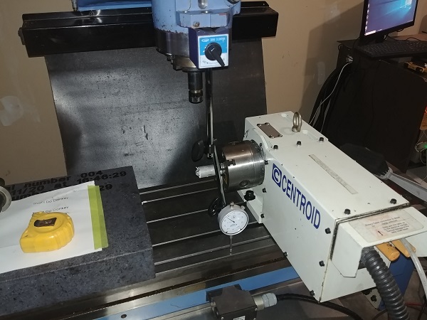
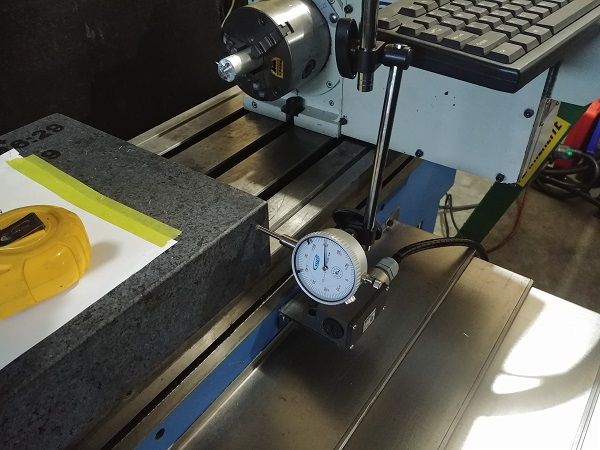
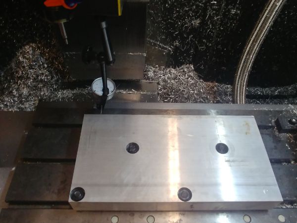
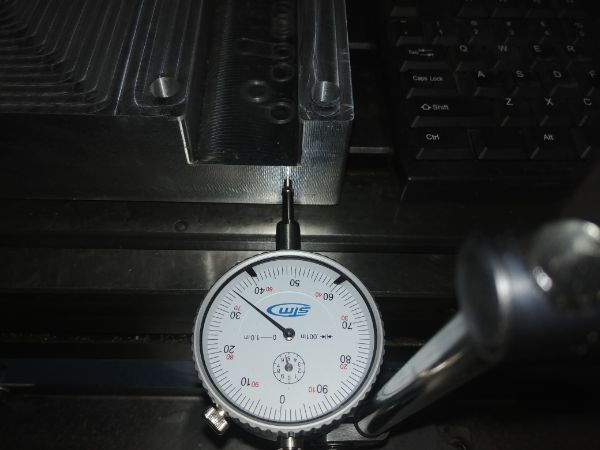
I thought I would level the milling head, this is something I never want to touch again. The distance I'll be leveling it over will be just over 15 inches, if I can get it to within a thou then I should be good.
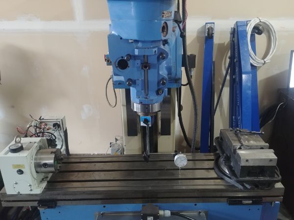
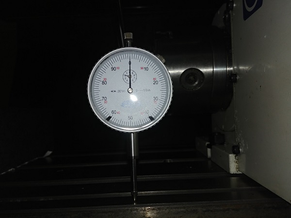
I spent a little time getting it as close as I could before tightening down the head bolts. Over a span of 15 inches I managed to get it pretty close, to within 0.0002".
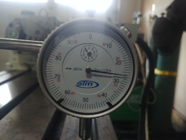
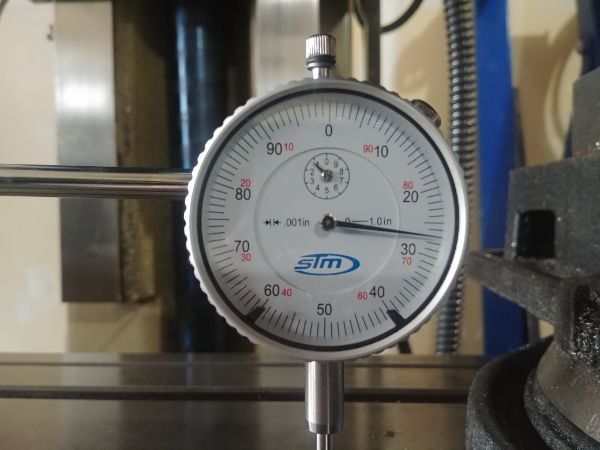
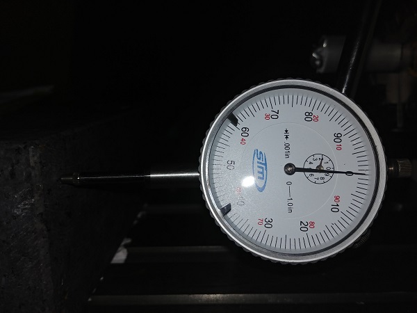
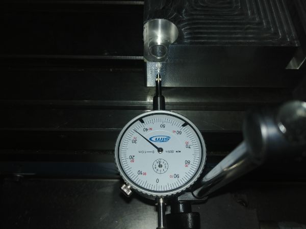
I checked it in the Y direction, 0.0005" over 7.5 inches which is acceptable.
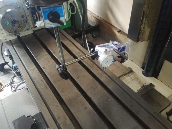
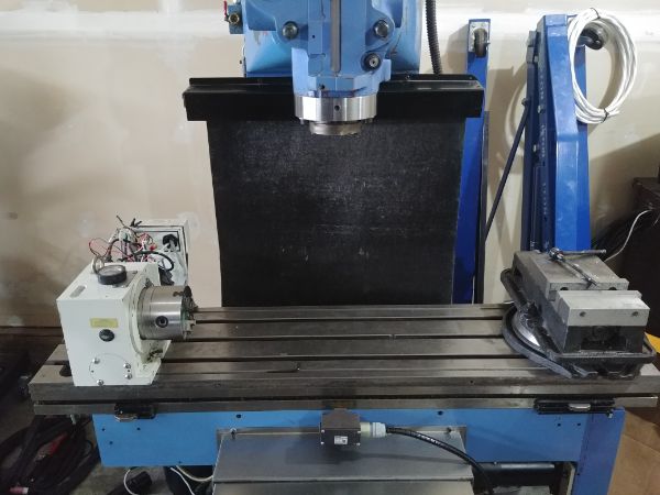
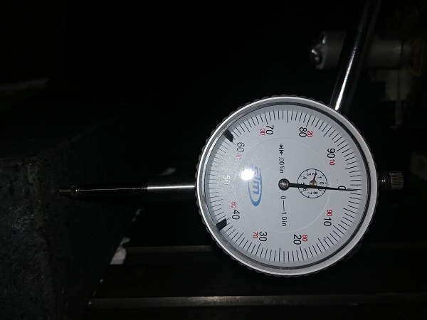
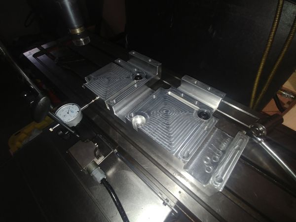
I chose to check the bed of the mill to see if it would ramp at all in the X direction, it turned out to be very accurate.
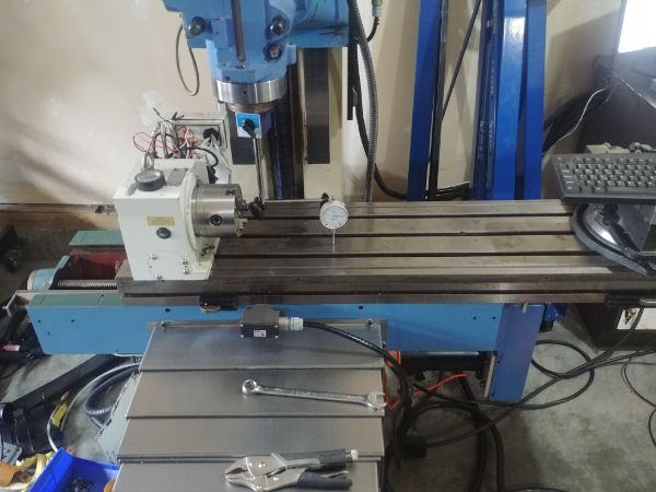
I am happy with how level the mill is in all directions. The next step will be to tune the back-lash and see how accurate I can mill a part. Before all of that I spent some time tuning the servo's as all of them made a notable noise. The noise is the servo trying to home on position by moving back and forth, I got them all silent. I then found out a cover for the Z and Y axis to stop swarf getting on the slides, I just need to work something out for the X axis.
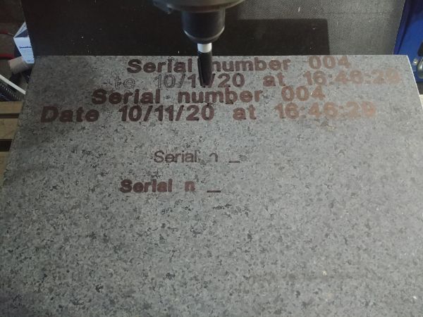
Since I got the machine working and the motors tuned I thought I would have a little play around. I have not tuned the backlash as I'm not ready to cut metal and make a mess yet. I instead placed a pen in a tool holder to run a program.
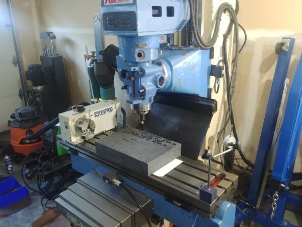
The results were pretty good.

I did some more thinking of how I was going to control the mess. I knew for starters that I would not use coolant at all because it makes swarf stick and generally makes a mess. I would like to use some sort of air for chip evacuation, but again that causes mess. I was going to make a simple enclosure around the mill but thought of an even better idea. I will place a curtain from the roof to the floor that runs on a rail. Once I am happy with the program I can pull the curtain around so that swarf only drops to the floor, I can then vacuum that up. I can then use air as a form of chip evacuation, it solves all of my issues. It might be a little slower working in this way, but I am only doing this for hobby reasons so I can take all the time I want.
I also forgot to mention that I simply cannot afford to buy the CAM package that I use at work, MasterCAM. I found that a similar software, Autodesk Fusion 360 achieves almost the same at far less of a cost. I downloaded the trial version, after a quick play it looks like something I will purchase. I still have access to an older version of Solidworks, a license that I could never justify the cost of upgrading. It seems that this software can do everything that I need multiple software's to achieve, that is CAD, CAM, PCB, simulation and 3D printing.
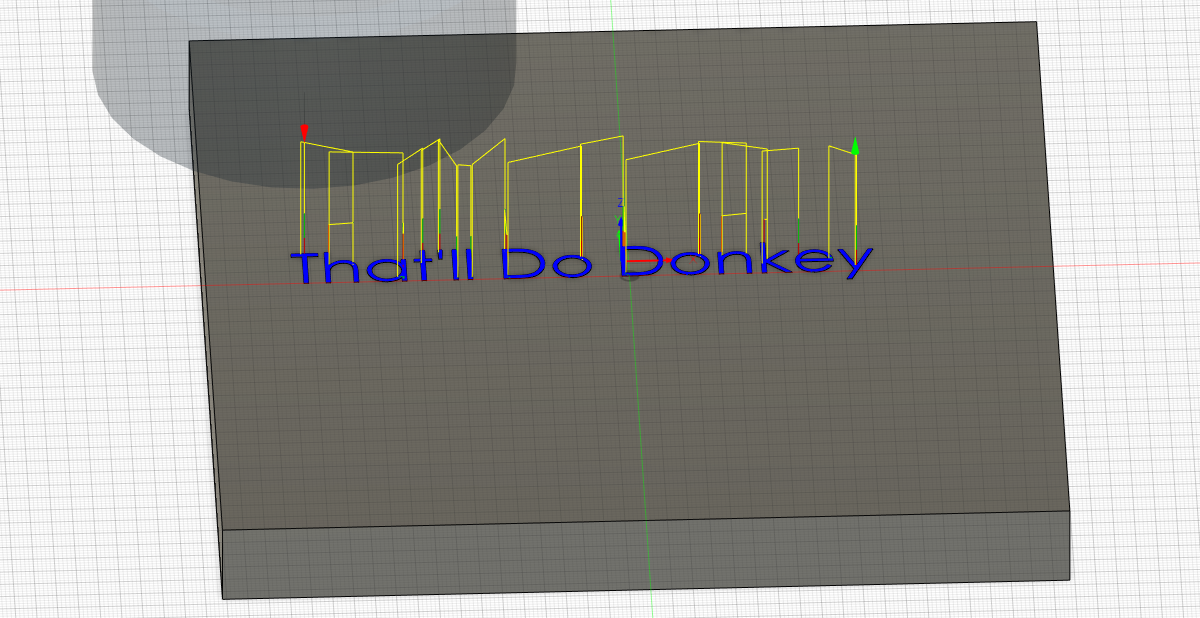
I have not really had the time to finish the mill properly, for the most I've just had a play around. I downloaded the software Fusion 360 to see how it would handle the fourth axis, it does a pretty good job. I created a model on Solidworks, a helix as shown below.
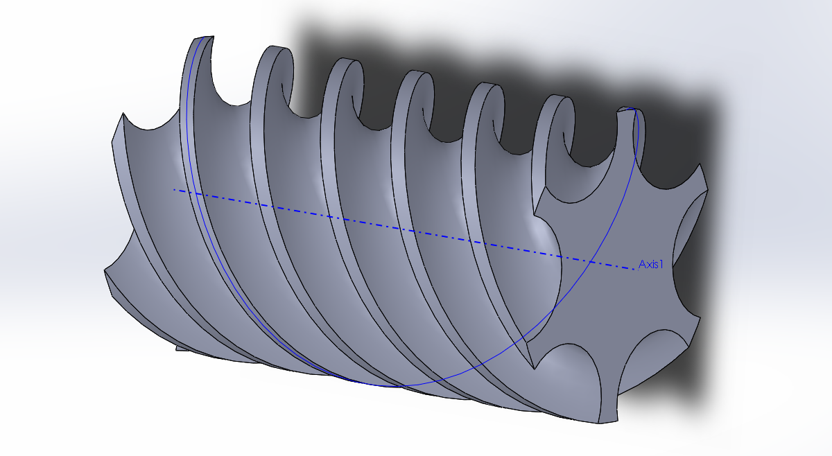
The software was really easy to work out, here it spirals a tool path around the outside.
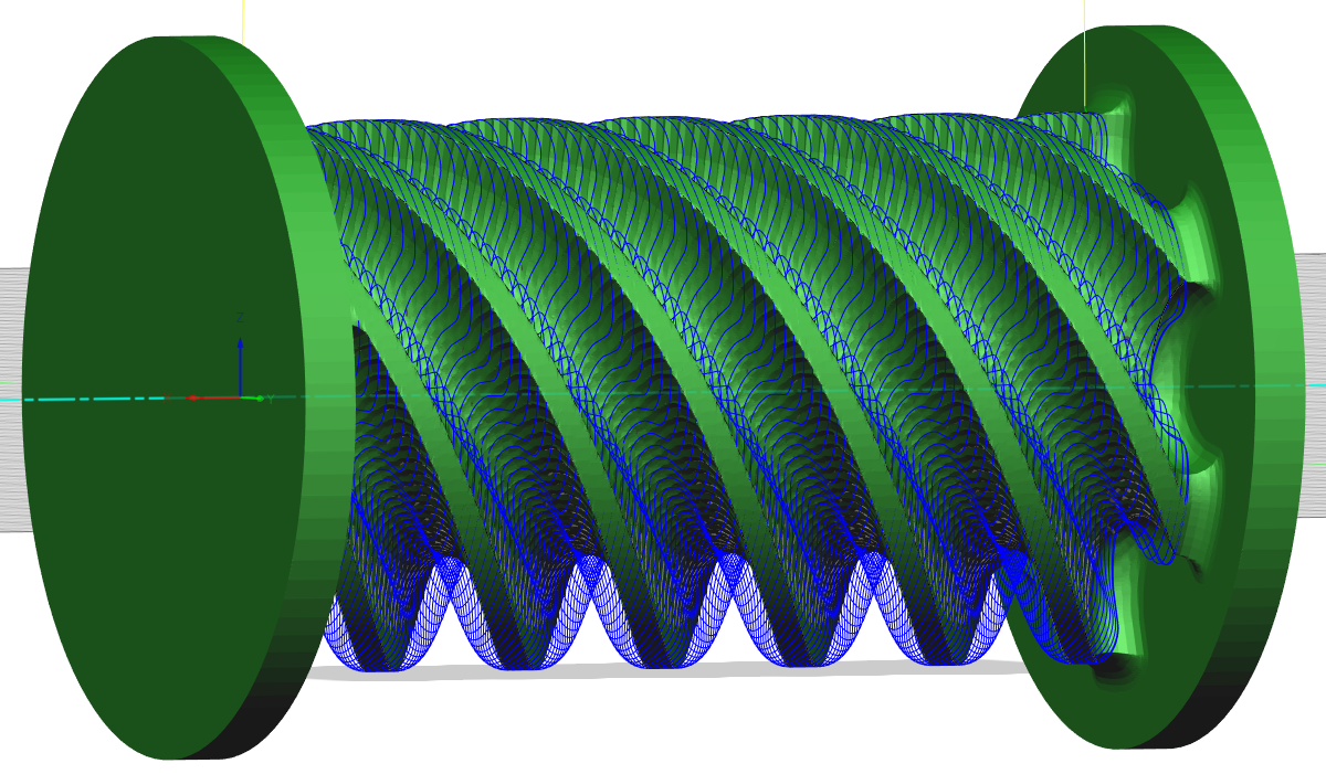
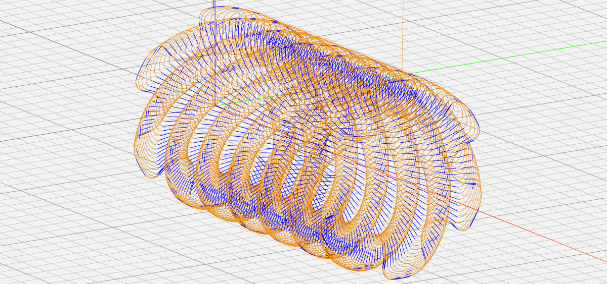
I had to enable the fourth axis in the post-processor, thankfully this was easy to do. To check the code I used an online G-code path simulator, all looks to be good.
I placed a piece of 32mm acetal in the rotary axis and ran the spindle at 3500rpm.
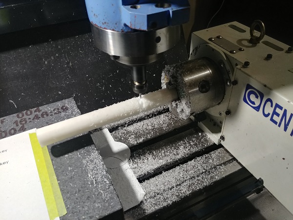
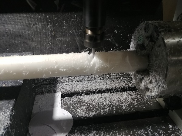
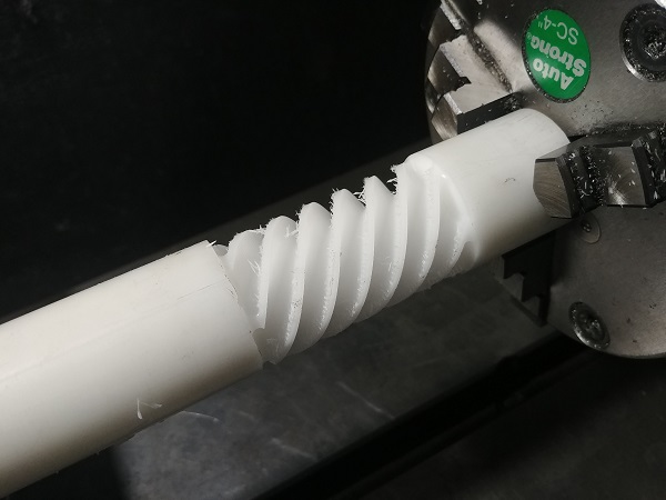
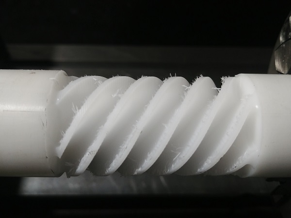
The part took around 25 minutes, it is around 2 inches in length. I have to admit that I was very impressed with the result.
I did have a further play with aluminium but ran into troubles without some kind of lubrication. It gave me a long think of what I can do on this mill without any type of coolant because I want it to be clean. I then remembered why I got this mill in the first instance and that is for the hydraulic press project. I should be able to do almost every single machining operation with the aid of the fourth axis.
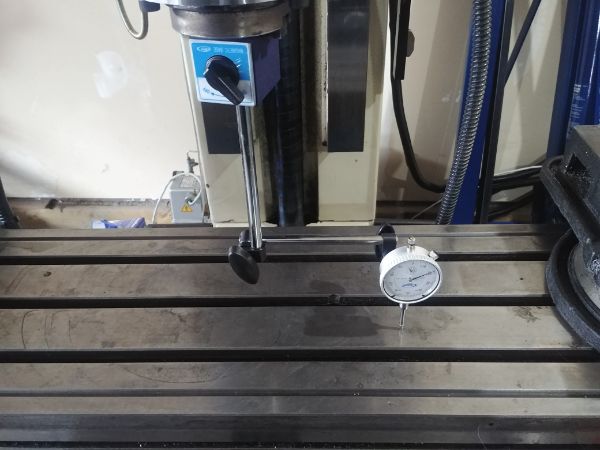
I decided that I needed to get the back-lash tuned on all of the axis, apart from the fourth. The fourth axis will likely only turn in a single direction and be doing operations that don't require crazy accuracies. To test the machine I will place it into manual increment mode. I will move it in a direction until the dial indictor starts to move and then move the axis back until the dial indictor starts to move in the opposite direction. The amount I increment in between the movements is the back-lash. To test this I then move the axis forward and backwards in increments of 10 thou (0.010 inch), with that I should see the axis move exactly 10 thou on the dial indicator.
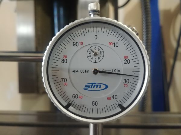
I first tested the Z-axis and found there to be exactly 1 thou of back-lash. I changed the software to compensate for this but it made the movement very erratic, this may be down to the counter-weight and the fact that it's belt driven.
I next tested the X-axis to find half a thou of back-lash. However once I made the increments 2 thou or more then the back-lash totally disappeared. This is down to the friction of the system, once it overcomes 1 thou of movement the friction suddenly drops.
The Y-axis was a different story and had 0.0035" of back-lash, even if I moved it in increments of 10 thou I still had the same number. This is the only axis that I could account for electronically, this made the back-lash zero. The Y-axis has to carry a lot more weight and has a lot more static friction.
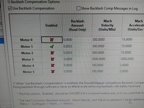
Overall I'm ok with the back-lash, it is certainly acceptable for what I want. The is a difference of opinion to how back-lash should be dealt with. Some believe adjusting it electronically is ok and others believe it has to be dealt with mechanically. I personally believe it should be fixed mechanically, if you want accuracy then purchase better screws. There are other things like having more pre-load on the axial bearings, more pre-load on the ball-screw nut (if design allows) and even loading the whole screw by stretching it (most industrial machines do this). In my case I feel it would require more modern screws as the bearings are torqued a little higher then they should be. The ball nut itself cannot be adjusted on my design without shimming. Sometimes back-lash can also be reduced by using thicker lubricating oil or greasing the ball nuts. One last further thing, use an old that is designed for slide ways. I do know we cheap out at work and use hydraulic oil in our machines, I have a feeling that is what is in the mill, so that can even help with accuracy.
I'm going to put this project on hold for a while since the only thing left is to get the spindle control worked out, for that I need to build something or change the VFD. Either way I have reached my budget limit on the machine, but that is not to say you won't see it machining in other projects.
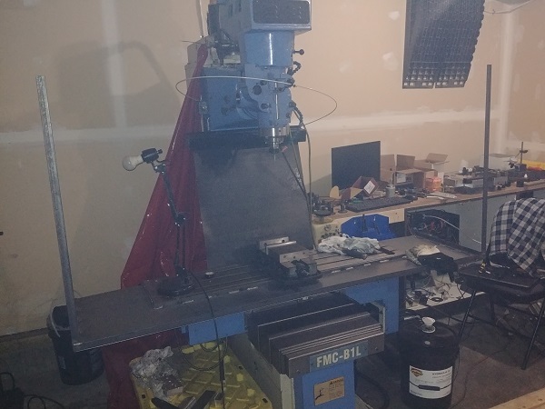
A quick little update, I extended my workbench and added a tool rack.
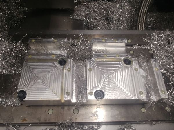
I used to use the milling machine at work and I was ok to do so, that has now changed, everyone is banned from using any work related tool. So in another project I have a lot of milling to do, this is an example of a part I was making, it was almost complete too.
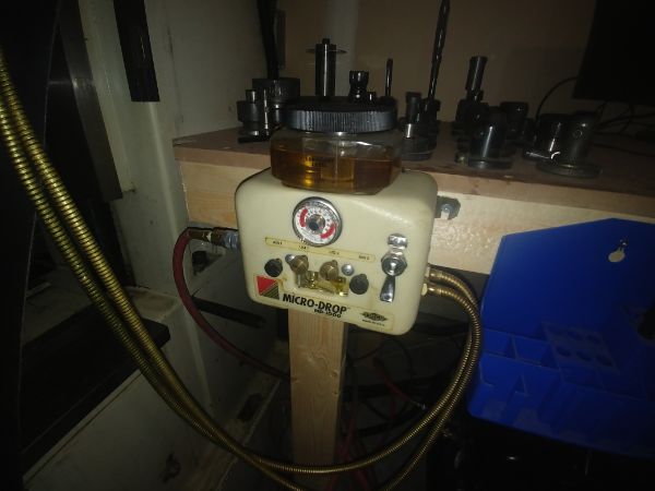
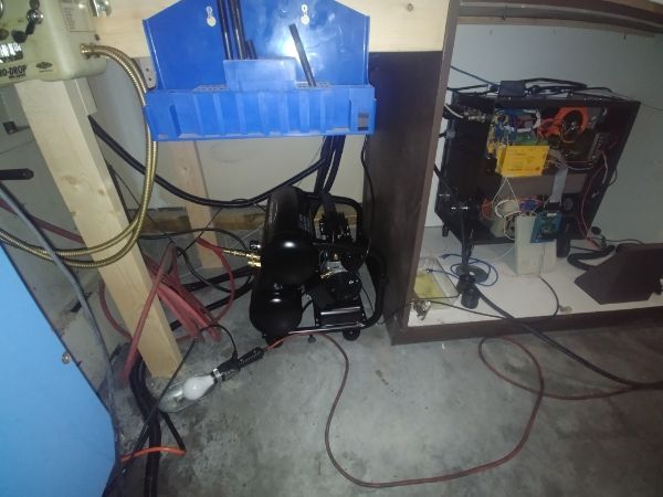
I refuse to use coolant on the mill due to the mess, but I can use a micro-mister. It took me a couple of hours to get this working, I had to take it apart eventually to find the issue, which was a simple fix. I bought a silent compressor to run the mister, this will run almost constantly when the mill is running. Aluminium is best machined with kerosene, but that is stinky and I don't want a permanent headache. I instead filled it with extra virgin olive oil, that should keep it healthy. I think the air blast should work better than coolant ever did for evacuating the chips and only a small amount of lubricant is needed to stop aluminium from sticking to the tools.
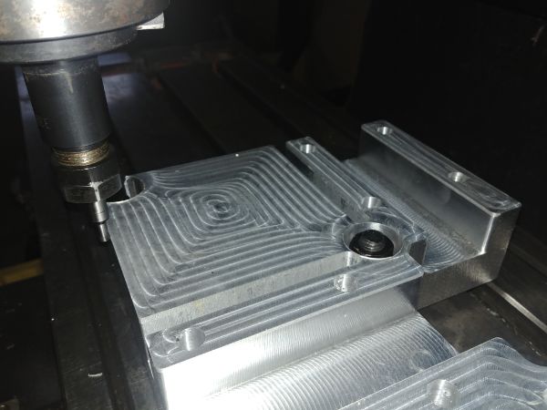
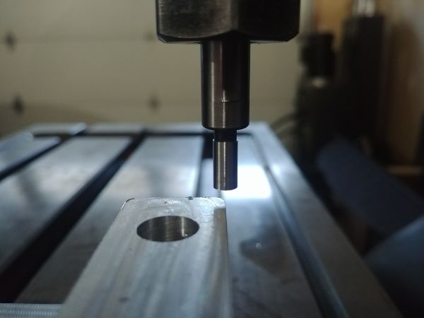
The pieces I was milling were drilled to suit the t-slots for the mill at work, but the spacing on mine is different so I will have to drill them again. I first started out by clocking the piece parallel on the mill.
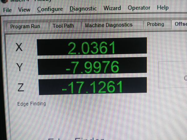
I then used an edge finder to set the work coordinates.
Take note of the Y coordinate in the first picture, this is the distance from one side of the block to the other, minus 0.1 of an inch. I originally made the part to be 7.9 inch and this shows it at 7.8976 which is still pretty close. I could not verify how accurate this was as I did not have a long enough caliper at hand, but I will check it soon. I then moved the machine to zero in MDI.

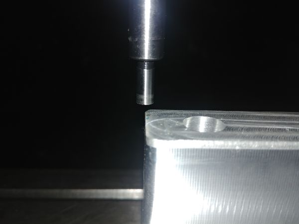
I gave a quick visual to see if I had set it correctly, the edge finder being centre of the edges.
The final test would be to power cycle the machine and home it again. I then touched the edge finder to the same edges to see how accurate the whole system would be as often I would not be doing everything in a single sitting. The first picture shows the X zero point, note that it will be out by 0.1 inch due to the diameter of the edge finder. Amazingly it relocated to within 0.0001", that is very impressive. I did the same with the Y zero point, this should be 3.95 inch, plus 0.1 inch for the diameter of the edge finder. This turned out to be perfect. I cannot ask any more of the homing switches, the final test will be machining something round.


I thought I should do an update since it has been over six months since I did the last one. I have done quite a lot of milling on the machine and so far it has performed just great. I did have some issues in that I updated all of the software and lost all of the machines parameters in the process. In the end I got it back to working how it should but had to revert back to the old software version.
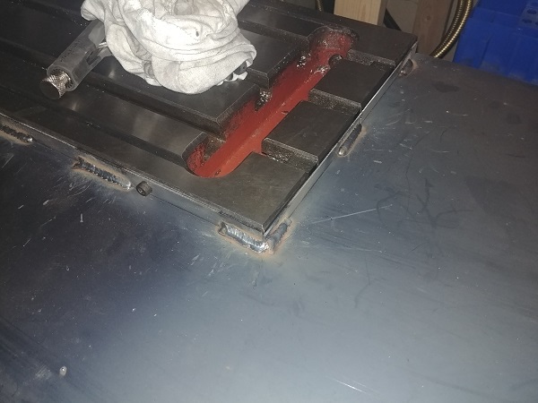
I also built a basic frame around the bed of the machine to catch chips, much better than using a welding curtain. I had some steel strips cut that bolt around the bed, I then welded in a surround. If for any reason it needs to be removed then it is simply unbolted. This tray also stops metal from getting on the slideways, very important since they are plastic.
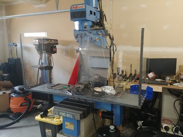
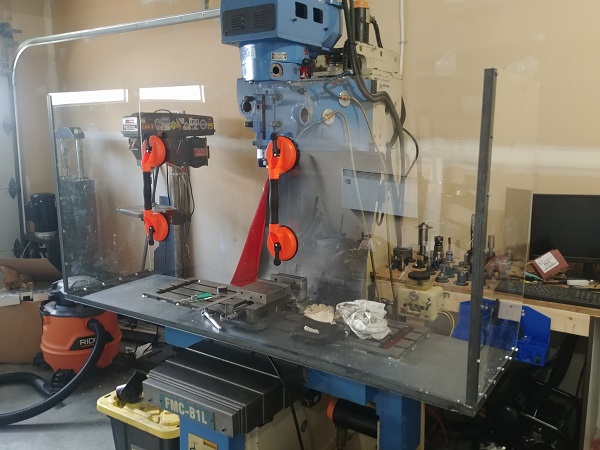
I bought some acrylic sheet as a protective screen. The side pieces are bolted in place and are not meant to be removed. The middle piece sits in place and can easily be removed with the aid of some suction pads. The screen is a little heavy but it is much better than having to clean up the mess without it.
It's doubtful that I'll update this project for a while. I would like to upgrade the ball screws and servos to achieve better accuracy.
Hello, if you have enjoyed reading this project, have taken an interest in another or want me to progress one further then please consider donating or even sponsoring a small amount every month, for more information on why you may like to help me out then follow the sponsor link to the left. Otherwise you can donate any amount with the link below, thank you!