Global Positioning System (GPS)
So pretty much everyone knows what a GPS is, if not it's a global positioning system. The world is divided into latitude and longitude which are measured in degrees. The latitude is the north / south axis and the longitude is the east / west axis. The purpose of a global positioning system is to pinpoint your current location via the used of satellites. Satellites know their own location in space, pinging off several satellites you can triangulate your position. On average it will use around five satellites to do this and normally a maximum of twelve for most GPS receivers.
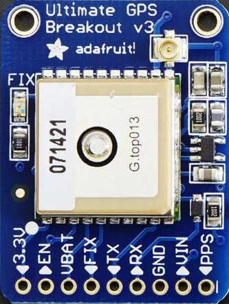
The best GPS module I have found is the Adafruit Ultimate GPS. It has a small footprint and can work up to a speed of up to 10Hz (10 samples per second). All GPS modules use the NMEA 0183 standard of protocols which states how the data is to be transmitted out of the module. The NMEA standard stands for National Marine Electronics Association. The 0183 standard covers a wide variety a protocols for both marine and aviation ranging from positioning systems to engine control.
An example of a message to be sent from my GPS module is;
$GPGGA,044534.000,1224.3211,N,12895.3287,W,1,03,12.2,1239.64,M,12.30,M,1.00,0123*6F
This may all look like a scramble of numbers and letters but this protocol is for the global positioning system fix data. It relates to Time and fix related data. So what does it all mean?
$ - This is known as the preamble which is the start of a string.
GP - The device ID, this example is a GPS but it could be for an autopilot - AG
GGA - This is the type of string data, this is the indication of the protocol we are receiving.
, - Between each piece of information is a comma, this helps split the numbers.
044534.000 - This is an example of time in the format of hhmmss.sss
1224.3211 - The latitude in the form of ddmm.mmmm (degrees and minutes)
N - North, the latitude.
*6F - This is known as the checksum, it is xor of all characters previous, this is to check for missing characters / a complete string of data.
I'm not going to explain everything on this protocol as if NMEA GGA is searched online you will find it's corresponding protocol.
The GPS module sends a total of six messages out;
GPGGA - Global Position System Fix Data
GPGSA - GPS DOP and Active Satellites
GPGSV - Satellites in View
GPRMC - Recommended Minimum Navigation Information
GPVTG - Track Made Good and Ground Speed
PGTOP - Antenna Status
RMC is the main protocol to be used in navigation systems as it has all the required information such as speed and location, it doesn't have pointless data such as satellite numbers and Id's.
This project was first intended to act like a GPS found in a car but this proved to require far too much data and a lot more time than I cared to spend on the project. Instead this project will show all of the GGA, GSA, RMC and VTG data while acting as a compass to direct you to the desired destination, also saved on the device.
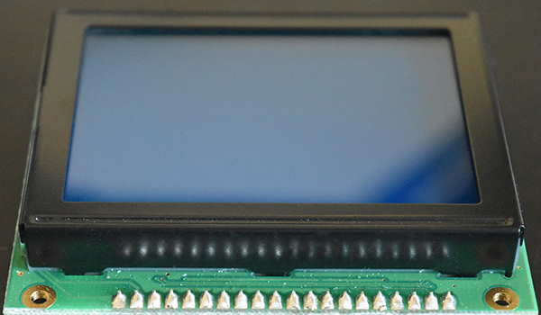
The display I have chosen to use is a 128 x 64 graphic LCD since I do not require it for any other projects, it uses transflective crystal technology which is very slow, it has been superceded by the OLED display. I had to go with the 16F887 due to it's higher pin count to cover the LCD and the input button options. The 887 has a maximum memory of 8k, I literally just scraped under this limit, I thankfully avoided the use of external memory.
Display
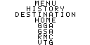
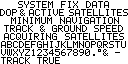
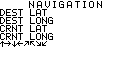
To the Design. Firstly I required some kind of a display title, I had to remember that each picture to the LCD would take 1kbyte of memory which limited me to 2k for the code and six images. The first image was the display title, nothing fancy as I had to manually input the bits. Here are three of the images, the title, a menu and some vital information. Since the data will be stored in one massive lookup table it means that I can access a single letter from either picture, hence the alphabet on the third.

It is quite possible that I could have used just the title image and the alphabet to type out all of these messages to the display, it may however have used less memory but it would have extended the main section to 4k, crossing pages is an easy way to introduce errors. When a call or goto is initiated it only loads 12 bits of the program counter, when crossing a page the 13th and / or 14th bit must be loaded manually and when returning to page zero these bits must be cleared.
Hardware
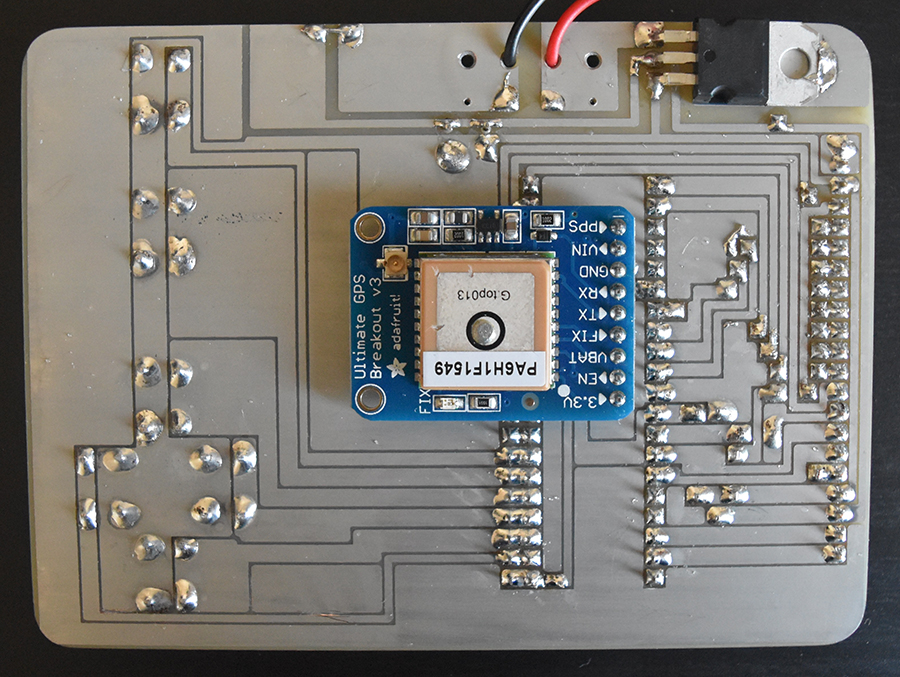
The GPS module, it has a really small footprint.
The LCD.
Code
This took an eternity to write, well two days at it, it took longer than expected due to issues with the LCD which I believed were caused by the breadboard. The issue was that when I wrote to the left side of the display when I switched to the right it copied the contents, why?, I'm not entirely sure but it meant using extra code to clear the right side before I wrote to it. The other problem I encountered was memory space, I actually ran out and didn't quite accomplish what I set out to do. The module was supposed to direct the user to the destination, in the end I had to settle for a compass, only a slight inconvenience to the user. I could probably make room but I really just wanted to get this project out of the way and for now it functions competently.
It would take me a lifetime to explain the whole code so I will just state the basics.
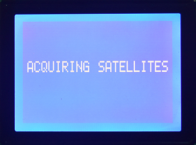
Firstly the splash screen is illuminated for a total of two seconds for which then the menu is displayed, the up and down buttons shift the cursor up and down. When the cursor is moved it resends the previous option with regular pixels, the new option has it's pixels inverted. When either the GGA, GSA, RMC or VTG options are chosen it starts by checking the GPS module to see if we have a satellite fix. There is a pin on the module that flashes every one second when there is no fix and every fifteen seconds when there is a fix. A delay of one second is set in motion, if the pulse is detected it starts again, if not the the satellites have fixed. While searching for satellites the display will tell the user that it is.
After this the serial receive register is polled until the $ symbol has been received, this states the start of a string. The program will skip the GPG and then check for G, S, M or T and then go to the option we chose. When the string is chosen it is written to the RAM using the FSR until we reach * which tells us to stop reading. The required data is sent out to the display along with the values we read from the GPS module, the display will continue looping, since information is received from the module every second it means the display will also update every second.
Choosing the history option will display the previous destinations, these are saved in EEPROM, there is also a pointer which tells us which location was written to last, also saved in the EEPROM. Choosing the destination option will let us go to the current destination, write a new destination or a new home. When the home or destination is written to it will save the values in the EEPROM, the destination option will also update the history. When either the home option on the main menu is chosen or the current destination option chosen it will take the values from the EEPROM and write them to the display.
Also on the display will be the current position updated every second from the GPS module. Some information also tells us the bearing we are moving, this is translated to an arrow pointing N, NE, E, etc... This is the little section I would have liked to improve on, instead of being a compass I hoped it would be used to navigate to the destination but I ran out of memory. Since the program took me so long to write and due to it working I really don't want to go over it and clean it up.
The Program - Text Version
Result
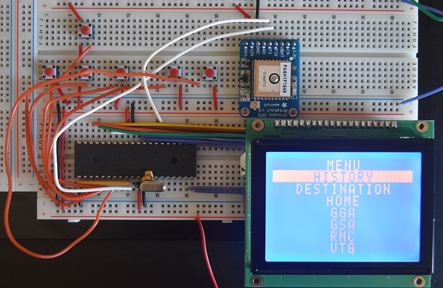
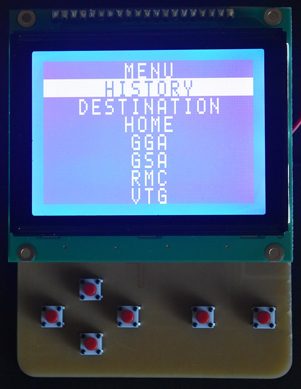
Here is the end result on a breadboard, the display showing the menu.
Finalising
Since I didn't need the components I chose to place this project onto a board.
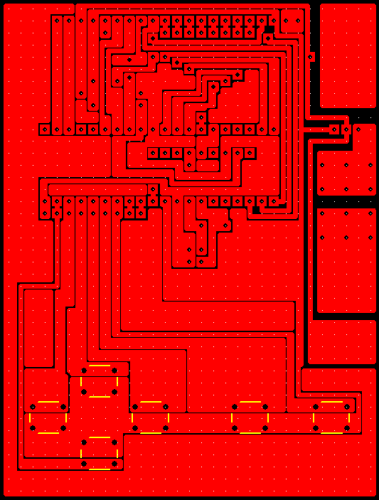
The finished board. I chose to place the voltage regulator underneath to make the top look cleaner, the regulator does get quite hot but it's certainly not going to overheat with the small amount of current present.
The top view of the finished article showing the splash screen and the menu.

Does it work?
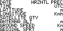
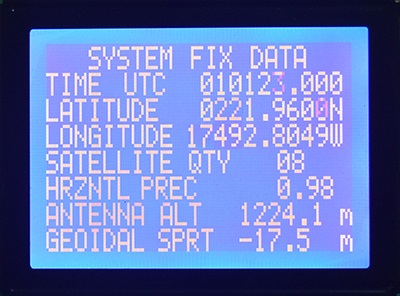
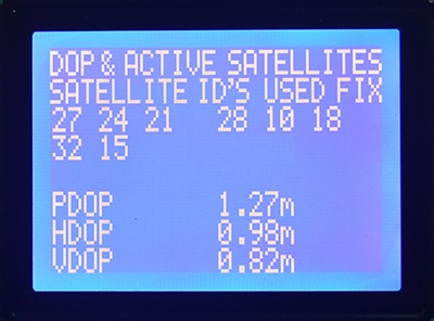
Yes. Choosing to look at the GGA data it first has to acquire the satellites, the manual says this could take up to 30 minutes but thankfully it only took around 40 seconds. I of course have edited the coordinates as I don't want to give out my address, so no I don't live on Howland Island in the North Pacific ocean, or do I? The second option is the GSA which tells us the satellite ID's and the position, horizontal and vertical dilution of precision, pointless data really.
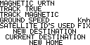
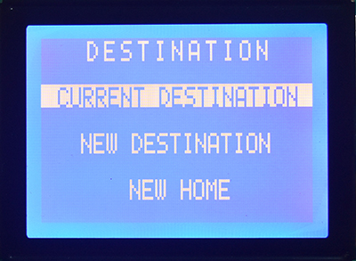
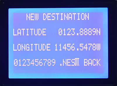
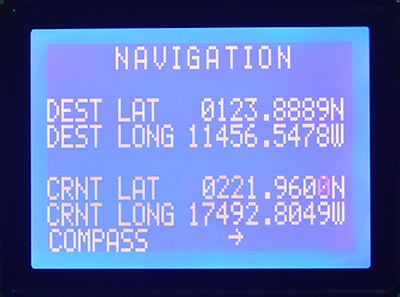
The next option I chose was the destination, I chose to set a new destination and then chose to navigate to it. I originally wanted the compass to point in the direction of the destination however I ran out of memory so just had to settle for a compass.
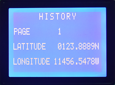
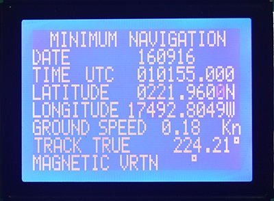
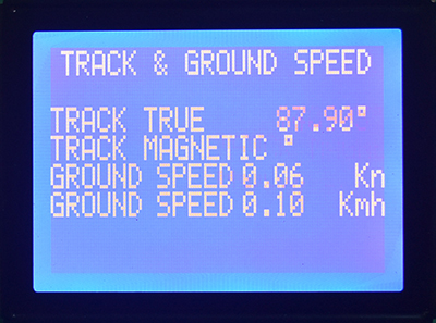
On the main menu I choose the history option, it contains the last ten destinations. The RMC and the VTG. The RMC is the recommended minimum navigation information which is what is used in GPS systems for cars, phones, etc... as it contains our location, speed, date and course.
Conclusion
Admittedly I really hated this project but I had a GPS module, no real use for it and needed a project to get it out of the way. It certainly wasn't difficult but the reason I hated it so much was the lookup table that contained all of the messages, it was 6k long and each bit had to be manually written. Another thing I hated was the issues I had with the LCD, it may have been due to the breadboard but for some reason when I switched to the right side of the display it copied the left side, this further increased code. Overall the project was pretty successful as it read the GPS module and displayed it on the LCD.
Please check out my other projects!
Hello, if you have enjoyed reading this project, have taken an interest in another or want me to progress one further then please consider donating or even sponsoring a small amount every month, for more information on why you may like to help me out then follow the sponsor link to the left. Otherwise you can donate any amount with the link below, thank you!