Grappling Gun - Page 4
September 25 / 09 / 2017
I have revived the project, it was recently shipped out from the UK over here to Canada. I again have the access to a basic machine shop, no TIG unfortunately but it's a useable shop. I now have a 3D printer too so I can make the guide for the rope which would have been almost impossible to make originally. One thing I really should have done is read through this project again because I was a little closer than I had originally thought.
First I thought I should go over all of the calculations again, this was just to give me an idea of what the project parameters were. The original idea was 10m in 2.3 seconds which I imagine wouldn't have been a great deal of fun, that was aimed towards my body weight but not theoretically of someone such as batman.
So my motor is 130Kv, 3000W at 37V which leads to a current of 81.1A and an impedance of 0.456 ohms at full power. From another project I will have a twelve cell LiPo to play with which means 44.4V, I'm almost certain my motor will handle the extra rpm's, of course I will still keep the power to a sensible 3000W as not not burn the motor, this also allows a lower current and a better life span of my batteries.
Where I left the project last was with a spool of 28mm, the part that will move the rope. A voltage of 44.4 along with a Kv rating of 130 will yield a motor rpm of 5772. The reduction stage of my gearbox is 4.4:1 and therefore the final maximum drive is 1311rpm. This equates to a distance of 115.4 metres per minute or 1.92m per second. It's not as fast as I initially wanted but it is still fast never the less. To reach the target of 10m it will take a total of 5.2 seconds with an energy capability of 3000W, this equates to a total of 15.6kJ.
Energy = mass x gravity x height.
15.6kJ = mass x 9.81m/s x 10m
mass = 159kg
Batman is supposed to weigh about 95kg so unless he gets rather chunky this gun would be perfect.
The first step was to take the gun apart to see what I was looking at, I really should have just checked out page 3 of this project. I made some quick sketches on how I thought the rope would feed, I then put this design together in a 3D CAD format.
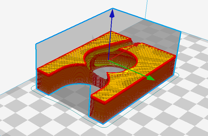
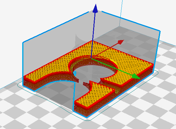
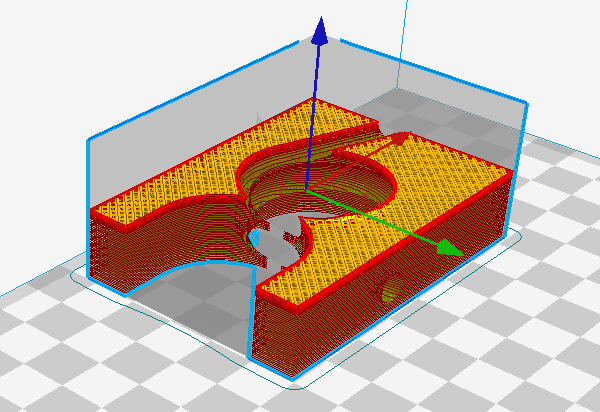
The model was imported into Cura to generate the g-code for the 3D printer, here is a layer view of the print around half way through.
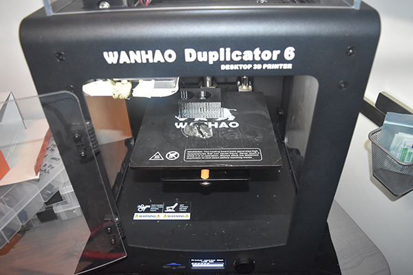
The part was printed in PETG, I used a 0.8mm nozzle which cut down on the accuracy but also greatly cut down on the print time.
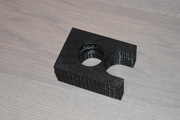
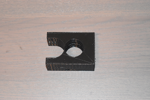
The part was a very tight fit, if this one does not work then I will have to adjust the CAD. So did it work, well it fed the rope but would not lift any more than about 20kg. I chose to look back through chapter 3 and realised that passing the rope between the rollers twice provided ample grip, this was of course the reason why I needed this block, to stop the ropes over-lapping and jamming. Oh well, I didn't waste my effort as I learnt that I needed to make some more clearance in the fit.
September 26 / 09 / 2017
I have revised the block so that the rope will pass through the rollers twice and increased the diameters of the holes to make a little clearance. I have also decreased the diameter of the path that the rope will pass through, hopefully this will not cause any issues.
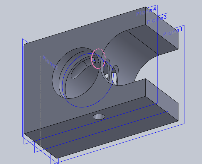
Some cross-section views of the new part.
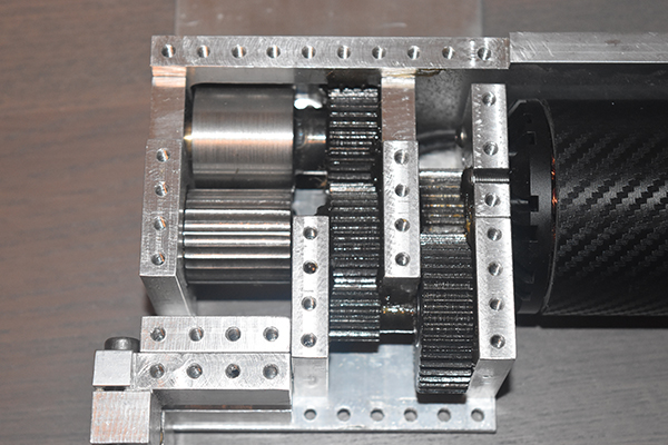
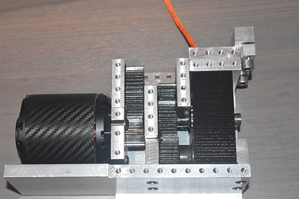
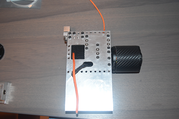
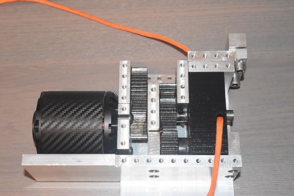
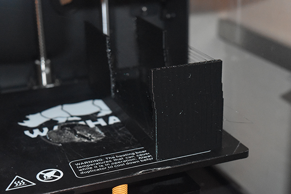
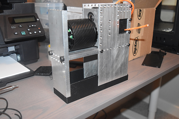
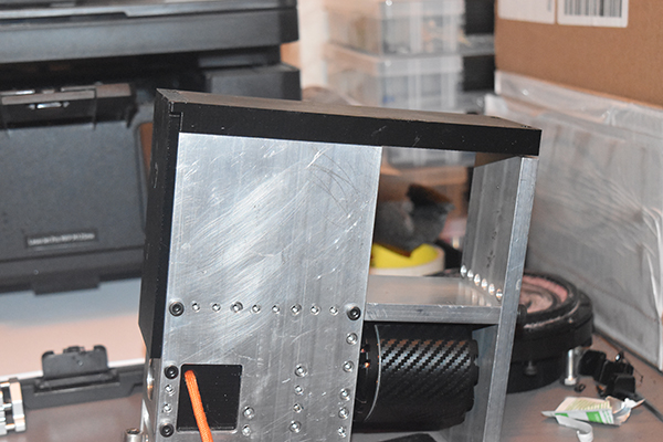
Here is the printed part along with it installed in the grappling gun. I fed the rope in through the top while turning the motor by hand, the rope appeared out of the exhaust port which means the system is perfect. The rope has perfect grip, the more weight the stronger it will grip. I think I will lighten some of the chassis by drilling it full of holes and work on some kind of a holder for the batteries, I'm so close to getting this thing working.
October 13 / 10 / 2017
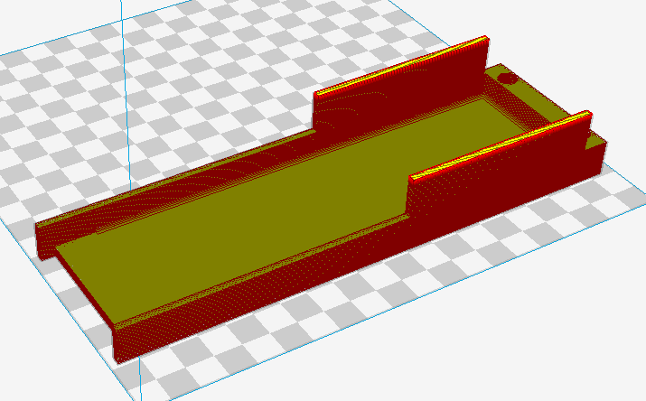
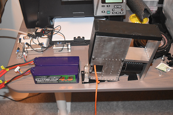
I'm now in the position where my supercharger project needs power and this project is ready for power too. Today I did a lot of research on the best batteries I could find for the price, I settled on two Turnigy batteries rated at 22.2V, 4.5Ah, 20C current capacity, they should arrive in a couple of weeks. The dimensions would suit the grappling gun rather well so today I though I should make a box to retain the batteries. This was the first design that I came up with, I thought that I could possibly have issues 3D printing the lugs to the left.
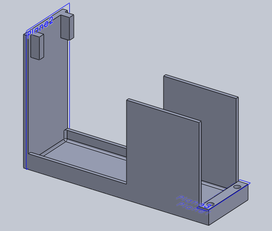
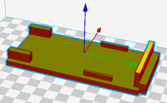
I did have some issues with the print, the printer managed to loose it's place several times due to me switching off the filament retract, the other issue is that if I turn the retract on then I sometimes get missing start points or over extrusion. The print was a failure but it made me rethink the design, it will now be made in two sections that will be glued together. Instead of the battery compartment being completely covered I instead chose for it to be partially as this will reduce the chance of the printer catching and loosing it's place again. The picture to the right shows how the finished result will look, of course the front is missing, not visible in the image.
October 15 / 10 / 2017
I chose to split the design in half, it will be bonded together. I set the first part to print, unfortunately late at night so I won't type it up until tomorrow.
October 16 / 10 / 2017
I set the other half to print.
October 29 / 10 / 2017
I made a mistake on one of the designs realising that it would be difficult to remove the batteries with the two little supports, they were removed and a few small modifications were made.
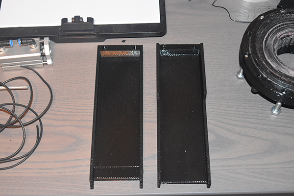
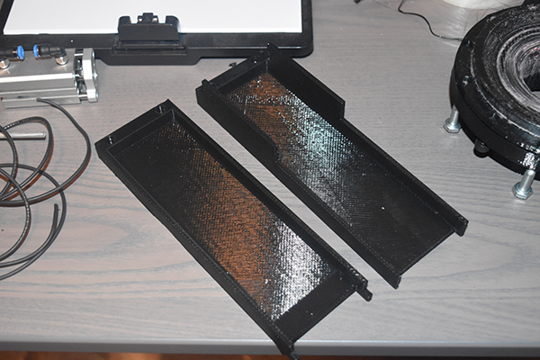
Here is the completed battery box just in time for the batteries I received through the post. I will put the project on hold for a little while since my electric supercharger project uses the same ESC, that project is nearing an end.
March 30 / 03 / 2022
It's been quite a long time since I did something on this project, much longer than when I started it. This would have been the first of it's kind at the time but now I believe a few people have come close or even matched this. Last year I was contacted by a company who saw this page on google and wanted me to build a professional unit. I later found out that one of the market leaders is using a design very close to this one, which is interesting. I now have my own machine shop so can build a much better version of this.
The company that contacted me was very convincing in the beginning, they made a lot of promises. In the initial stage I did a lot of research and design on a completely new system, one that would vastly surpass this one. Eventually they got me to sign an NDA which turned out to be a waste of time. They never sent me a single ounce of information as to what was happening on their side. We would have meetings in which they assured me this was going ahead. In the end I chose to invoice them for a small portion of my time, in which they avoided. To cut a very long story short they could not part with a small amount of money, giving me no reason as to why. My question was how could they invest money in this idea when they cannot pay me.
I'm pretty sure all they were doing was fishing for information or design ideas. I'm sure that I am not the only one they've pursued, so I'm in the position where I'm considering reviewing them online. Not paying for my services is something I really don't want to pursue legally since they're in a different country, but an online review will stop others just like me from being stung. The whole experience has taught me quite the lesson, and that is talk is just talk.
A positive experience has come of this however, I now want to pursue this project again. After doing a lot of research on the competition I believe I can build something to surpass them all. Around six months ago I came up with a new mechanism for the rope, which is just a prototype, but no one has used it. The issue with every design out there is how it is going to hold the rope without damaging it. Another issue is making something that can access a rope midway through without having to feed it from one end first. Just recently I came up with a new design that will accept any size of rope from 7 to 12mm and can be easily attached midpoint on a rope. The design is so robust that I can operate the unit underwater without any issue.
The plan is to finish off the above ascender since the mechanism does work, and to get it looking less "prototypey". I also have plenty of places where I can test it out too. I'm also working on a new prototype with my new mechanism, that I will not be publishing on here since it has the potential to be a world leader. It is likely I will do videos of the progress, just not show the inner workings. I have the capability to make a lot of money if this works out, and the workshop of my dreams.
April 02 / 04 / 2022
Success ! I dug the project out of a box and took a look at the original mechanism. The plastic guide block that I 3D printed was over-size meaning that when bolted together it caused the rollers to bind. I sanded down the sides and assembled the whole thing. I bought a servo tester so that I could control the speed of the ESC and then wired everything up to my power supply. I fed some parachute cord through the mechanism and then fused it together, I had a continuous band of rope with a length of 2.64 m. I set the power supply to 48V and recorded the results. Here is that video, plus some explaining in the beginning.
I originally worked it out at 1.92 m/s but I achieved 2.4 m/s in the video, not quite sure why, but that's a bonus. So what is the next step? Well I don't really have the money to spend on new batteries but I might be able to charge them, hopefully. Most importantly I need to mount the ESC properly and attach a potentiometer switch to control the speed.
Hello, if you have enjoyed reading this project, have taken an interest in another or want me to progress one further then please consider donating or even sponsoring a small amount every month, for more information on why you may like to help me out then follow the sponsor link to the left. Otherwise you can donate any amount with the link below, thank you!