IGBT and MOSFET Desaturation Protection - Page 2
In the previous page I mainly discussed the voltage or Vsat detection method to prevent an IGBT from saturating. There is a huge problem with this method as a huge current has to flow before this condition is triggered, since the current is high the inductance in the circuit creates a huge voltage spike. This method is quite commonly used but it's quite a bad option to choose, if I was to be driving a MOSFET then it would have cooked itself before I could turn it off in time, let alone the voltage spike killing it.
So what is the other method, well it is actually the most simplest and involves the use of a current sensing resistor. The resistor only has to have a very small value as a comparator will be reading the voltage drop across it. Remember that power is equal to current squared multiplied by resistance, so take a 0.01 ohm resistor at 10 amp, that's only 1W of power. There are normally two circuits, one that reads the maximum current to pass and acts like the desaturation circuit and the other is simply for regulating current. This circuit is much more simple to build, you can easily calculate the threshold current and you can stop huge currents from passing.
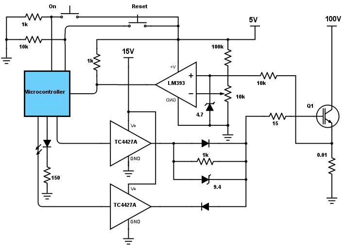
This circuit only contains just the one comparator for over-current conditions, a second comparator could provide feedback to the control circuit to alter the PWM.
There are very few comparators out there that will measure one of the reference points at close to 0V, most are around 0.5V. Say for example I set the current at 10A, that is only 100mV across the resistor, far below the region for most comparators, the LM393 is the only one I know of that will allow either of it's inputs down to 0V.
I have also reverted back to the old zener diode design as this provided the fastest turn-off time for me although I have tried a different 10V zener and it worked out slower than the MOSFET method, again a lot is trial and error.
Below is the circuit, it's fairly simple.

Here is the over-current condition, the purple trace is the gate input, the yellow Vc and the blue the output stage of the comparator.
The over-current condition is by shorting the load resistors above the IGBT collector.
As you can see from detection to the IGBT being off (the yellow spike) it has only taken 7us.

This second condition is turning the IGBT on with a shorted output.
As you can see there is a delay of about 2.2us from the gate being on to the comparator detecting an over-current situation.
1us of this was placed in the program, 200ns the on-time for the IGBT and the remaining 1us is the response time of the comparator. The reason I chose not to use the LM393 in the first instance is due to it's slower operation times however to use a different comparator would require me to have a split supply adding to the complexity of the circuit.
The MOSFET
The IGBT is rather robust and allows us quite a lot of time to turn it off in the event of an over-current situation, there is enough time to "soft" turn off helping to prevent large voltage spikes. So what is the difference with the MOSFET, well it has a much lower voltage drop which equates to a faster rise in current when a over-current situation occurs. In reality your not going to find a MOSFET that can withstand more than a 3us short-circuit, most are only are 2us.
Quite simply a detection method is used to detect the over-current situation, when it occurs the MOSFET is shut down and that's it. There is no two-step turn off like that for the IGBT, consequently there will be a huge voltage surge, however these can be "snubbed" with a capacitor, resistor and / or a zener diode.
The MOSFET will almost exclusively be used for switch mode power supplies and rarely have to deal with a "dead short" situation. Even when they do such as the output to a motor controller there are plenty of other design considerations to prevent voltage spikes.
Conclusion
There were two methods I discussed for over-current protection, the saturation voltage method and the current detecting resistor method. If you are quite simply trying to protect an IGBT from a short circuit then the voltage detection method is viable although it gives little indication to the amount of current present, the detection can however fail as if the current does not rise fast enough then the IGBT could be cooked before the circuit can turn it off in time. For the MOSFET the voltage detection method would be far too slow, it is not discussed as it would be almost impossible for it to save the component in time.
The resistor current detection method is by far the best as the circuit can both detect a short-circuit and provide feedback to the control circuit of the current being drawn. This method is both suitable for the MOSFET and the IGBT due it's almost instant detection (depending on the comparator). The only issue is that a dual supply must be used for most comparators since the input voltages are only around 0.5V minimum, however the LM393 is a slower alternative but can operate at 0V input.
A two-step turn off can be used on the IGBT but not the MOSFET, a drop of around 9-10V is ideal to reduce the voltage spike at the collector. The two-step turn off is only an aid as the inductance in the circuit is the cause of the voltage spike, the only way is to incorporate some kind of a "snubber". The snubber normally has to be chosen to fit the operating frequency and will result in some losses, another alternative is to use high-voltage zener diodes to remove the spike - note that a resistor in series needs to be used otherwise it will temporarily short the supply when conduction occurs.
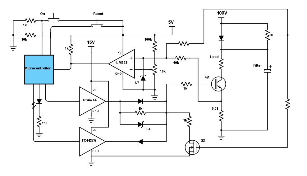
Design note - A large filter capacitor across the supply will dramatically reduce voltage spikes, however it will also add to a higher short-circuit current. The detection should prevent component failure.
Design note - When the power is cut the filter capacitors will hold their power, the control circuit will also loose power which may cause the IGBT to slowly turn off, this could result in component failure. A comparator circuit should detect the supply voltage, when it drops sufficiently low enough the control circuit will turn off both IGBT's like in a short-circuit situation. A back-up capacitor should be used on the control circuit to keep the IGBT's low while either a relay disconnects the supply including the filters or a clamp circuit keeps the gates at zero until the filter capacitors have fully discharge, a bleed resistor across filter capacitors is a "must". Most IGBT controllers will pull-down the gate when power is lost, however if you using an inverted input driver and the controller circuit turns off before the driver then this could raise the gate on both IGBT's resulting in a short across the filter capacitor. (I'm assuming the circuit is either, half or full bridge).
The below circuit will keep the circuit in "over-current" detection mode until there is a supply present (the 100V) until it's reset, this prevents the control circuit from turning on when there is no supply voltage. The 5V logic to the microcontroller will have a back-up capacitor across it and will last considerably longer than the 15V that supplies the driver chip, when the 5V runs out it's outputs will not affect the driver chip. Also while there is no power being supplied to the filter capacitors there remains a voltage present until it is discharged (there should be a bleed resistor across it, although not shown in the diagram). The voltage difference between the supply and the filter goes to a potential divider which if the voltage difference is more than "X" the MOSFET will turn on and pull the IGBT gate to ground. When running under normal conditions there is no voltage between the divider and therefore the MOSFET will remain off.
Hello, if you have enjoyed reading this project, have taken an interest in another or want me to progress one further then please consider donating or even sponsoring a small amount every month, for more information on why you may like to help me out then follow the sponsor link to the left. Otherwise you can donate any amount with the link below, thank you!