Microcontrollers 6 - Keypad Input
We know how to display some characters or some writing on an LCD but now we need some kind of an input, such as a keypad. A keypad is great for data entry, I have chosen the 4x4 keypad as this one is alphanumerical. The program will scan the keypad for an input, when a button is pressed it will scan which button, the program will wait until the key is released before writing the character to an LCD. In this project I will also discuss the "PCL", "PCH" and "PCLATH" as these are needed when dealing with data tables. In the next chapter I will discuss how to deal with storing more data from the keypad and how to deal with larger programs.
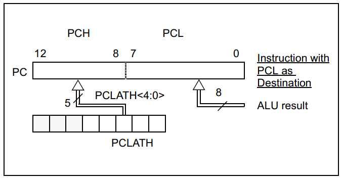
First I will talk about the program counter as this increments through the memory addresses and can be extremely useful for jumping to specific location in a program.
The lower 8-bits of the program counter (PCL) are read / write-able whereas the higher 5-bits are not (PCH). However "PLCATH" is a write-able register, whatever is written to this will be placed into the PCH.
Care must be taken when modifying the PCL as an incorrect jump in a program or crossing something called a memory block can cause a jump to the wrong place in the program. I will discuss how to look out and deal this this concern.
When reading the terminology you will come across pages and page boundaries, now these sound like the same thing but they're not. Firstly a page boundary is dealing with the main program memory blocks, the first 2k of memory being page zero and the second being the next 2k of memory. I will deal with page boundaries in a different chapter as problems will occur when using "goto" and "call" commands. A page is known to be 255 bytes, it should really be referred to as a memory boundary, for example the start of the program in hex is 00, one page would be 00-FF, the next page would be 100-1FF and so on. The PCL contains this address, so as you can imagine if your offsetting just the PCL and it increments over this address then it will overflow, in the lookup table program this would cause it to randomly jump to an earlier position in the program.
To counteract this problem with a lookup table you first need to check whether the PCL offset will cause an overflow, it if does all that has to be done is the PCH has to be incremented, but first how will you know if a page is going to be crossed.
The best way is to first write out the program with the lookup table to see if further actions need to be taken.
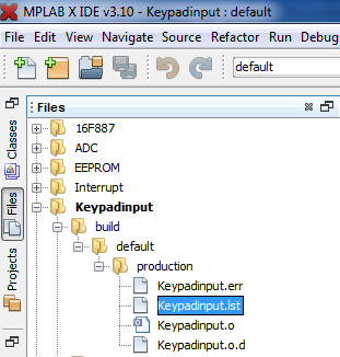
Click on the "Files" tab at the left side of the screen, click on your chosen project and make your way down to the ".lst" file. This file contains everything in your program and shows where in the memory it will be placed.
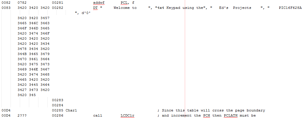
Below is an extract of my program, the far left is the memory location in HEX. As you can see for this example my data table starts at the location "0083" and ends at the location "00D3". When adding the offset to the PCL with a value such as one, all I'm doing is offsetting this "83" to "84" and so on, so imagine if this suddenly becomes zero, it will move the program to an earlier point. All you need to look for in the program is that the third digit in the address does not change, if it does then a page has been crossed.
I have two lookup tables in my program, the first table displays the welcome message and then the second table displays a value from the keypad. Below is the program for my second lookup table.
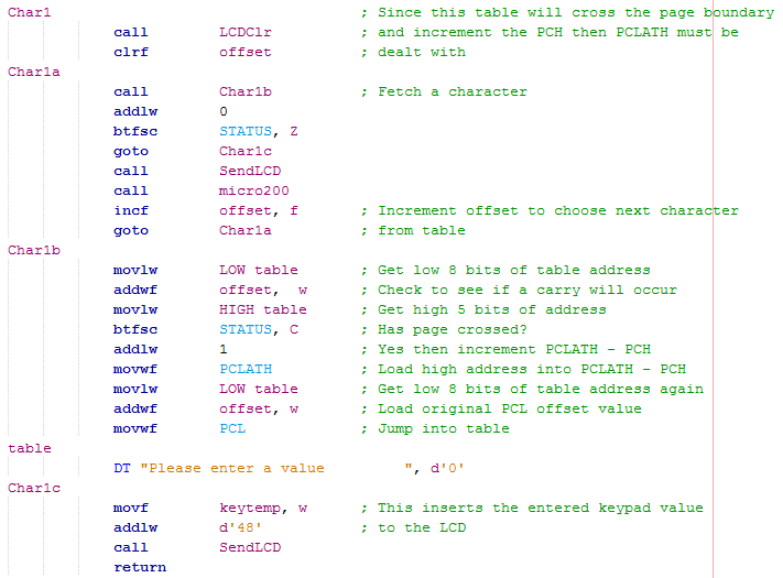
The first half of the program is essentially the same, all it does is clear the LCD, set the offset to zero and then increment the offset after each character has been called from the table and sent to the display.
One more addition is that the display doesn't return straight away, it goes to another program to output a variable to the LCD, variables cannot be placed in a lookup table.
Using the "movlw" command and then a label will load the labels address to the working register, since an address is 13-bit you have to specify weather your dealing with the low-byte or high-byte.
By adding the offset to the low-byte of the address we will know whether the PCL will roll over, if it does then the PCLATH has to be incremented by one.
The low bytes of the table are added with the offset and placed in the PCL. Since we have added the location of the table to the offset and placed this into the PCL it will automatically jump to the table and shift to the character it has been offset by.
Here is my updated program, It's a little more programming but it's an absolute must for the table to work correctly. Note that by placing the location of the table in the program counter means that the table can actually be situated in any page boundary of the program code, this will be discussed in a future chapter of why this is so important. Now to the program, all it does is display the entered character from the keypad to the LCD, here is a copy - Program
Here's a visual representation of what the circuit may look like on a breadboard, note that there should be a 50 ohm resistor between the supply to the backlight on the LCD, inputs should also have pull down resistors, 4k7 ohm.

Here is my circuit below on breadboard.
So now we know what must be done to a lookup table if we need to cross a page and we know how to read from a keypad and display it on an LCD. The next chapter deals with memory, direct and indirect addressing.
Hello, if you have enjoyed reading this project, have taken an interest in another or want me to progress one further then please consider donating or even sponsoring a small amount every month, for more information on why you may like to help me out then follow the sponsor link to the left. Otherwise you can donate any amount with the link below, thank you!