Repair of a MIG Welder
14/03/2012
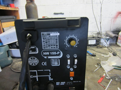
Earlier this month I was asked if I could have a look at a MIG welder in order for me to repair it.
A mig welder feeds steel through a nozzle at a constant rate specified by the user, where at this nozzle power is applied while being mixed with an inert gas such as Argon or Carbon dioxide. The wire touches the work piece and completes a circuit, the current is high enough to melt the wire and the workpiece, this fuses them together. The inert gas is to block out other gases from the atmosphere such as oxygen which would oxidise the weld making it brittle and structually poor. The problem with the welder was that the motor that fed the steel wire was just humming and not moving, after some fault finding I decided that it was the motor controller board. The purpose of the controller board is to allow the user to vary the speed of the motor and therefore the speed at which the wire comes out of the welding tip, when a trigger is pressed on the welding gun it turns on the motor and applies power to the nozzle.
So I had a look on the internet to see how much a replacement board was, £50. The client wouldn't be willing to pay this amount so I designed and built a board myself for about £5.
Power from the mains goes to a transformer which steps the voltage down from 230Vac to 12Vac, the 12Vac is converted to about 17Vdc with a bridge rectifier. This 17V source is then placed through a voltage regulator which steps it down to 12V, it is then sent to the trigger on the welding gun, when the trigger is pressed it allows power to flow to two circuits; the PWM and relay circuit. The relay circuit connects the mains power to a large transformer in the welding unit powering the nozzle. The PWM (Pulse width modulation) circuit controls the wire feed motor, all this does is turn a transistor on and off very rapidly to regulate the power to the motor, the user can control how long the turn on period is. The motor is connected to 12V and the transistor which in turn is connected to the PWM circuit, turning the transistor on for a longer time allows more current to flow in the motor making it turn faster.
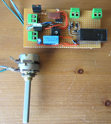
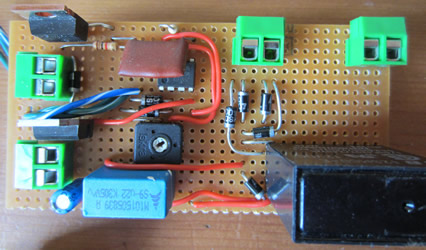
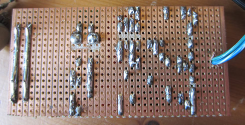 Most simple circuits like this I make up as I go along and write a schematic after I have built it. I found out some suitable components and a piece of circuit board, about an hour later the board was complete. The soldering wasn't great as I needed a new tip for the iron.
The next step was to install it into the welder, I managed to cut out a few unnecessary wires and learnt how simple mig welders really are.

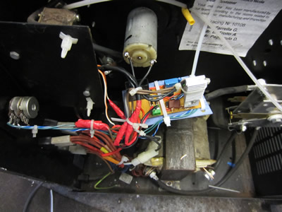
It wasn't quite as neat as I would have liked but it was certainly a lot tidier than when I first looked at it, the most important thing was that it worked perfectly, hopefully it should last a lot longer than what the original did.
15/03/2014 - The welder was sold on just days after me fixing it, to a neighbour, but just over two years later its still functioning.
Hello, if you have enjoyed reading this project, have taken an interest in another or want me to progress one further then please consider donating or even sponsoring a small amount every month, for more information on why you may like to help me out then follow the sponsor link to the left. Otherwise you can donate any amount with the link below, thank you!