CNC PCB Engraver / Mill
This page will be a little hectic, there will be a link to something more detailed at the bottom. For quite a while I have been making circuit boards using the photo-resist method. This involves printing a negative trace on a piece of film, the film is placed against a pre-sensitised copper clad board. A light develops the circuit board traces onto the board. It is then placed in an etching solution which removes all of the exposed copper, only leaving the traces behind.
This method produces excellent results and a high degree of detail. The issue is that the boards I received were never consistent. Some developed at different rates, some had scratches and some were completely defective. I decided that I did not want to continue wasting time or money. I looked into getting a CNC engraving mill, unfortunately they are very expensive new. I managed to pick an old one up cheap.
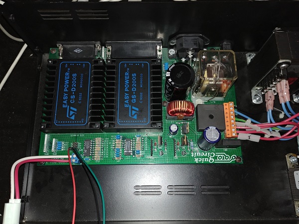
This particular model is called the Quick Circuit 7000.
Specs:
13 x 19 Inch Work Area
18 x 24 Inch Bed
24,000 RPM Spindle
180 Holes / Minute
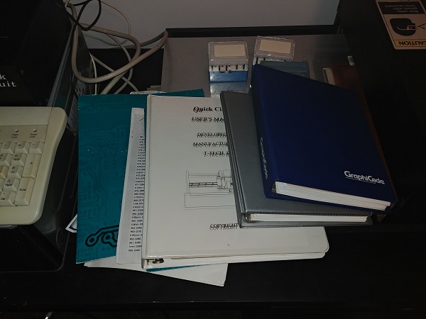
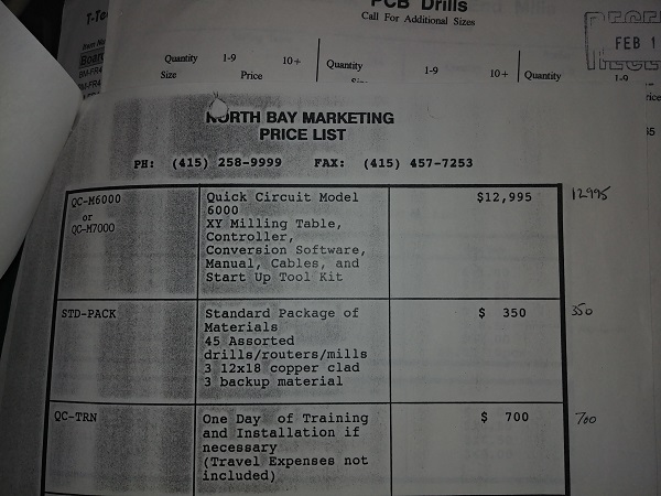
It is quite amazing that I pretty much got everything with this machine, it is 26 years old. I got some manuals showing how to use the software, it is pretty neat to read through but I have no intention of ever using it, modern software is so much easier and faster. What is very interesting is that I have a price breakdown of all parts, options and packages. I do know that North Bay is in Ontario so I can probably assume the prices are Canadian. Using an inflation calculator this machine would cost $20,743 as of 2019. I paid $900 CAD for the machine, $500 of that was courier charges due to the weight.
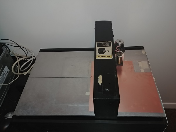
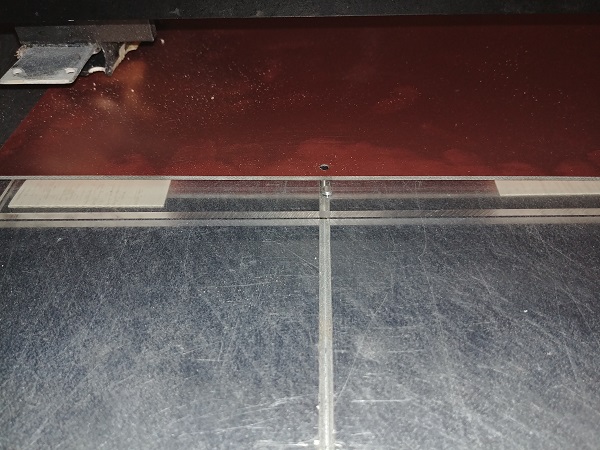
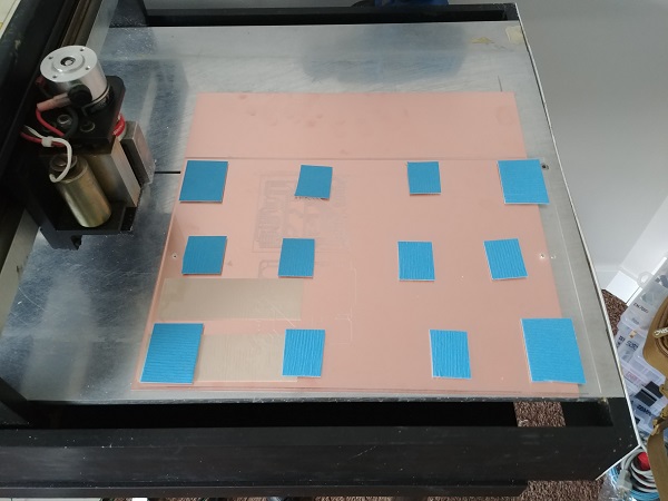
I don't believe I will ever need to make a circuit board the full size of this mill, but I certainly have the capability. The nice thing is that if I need to make a batch or a multitude of different boards I can do so in one shot. There is a slot running the full length of the bed, this runs perfectly parallel with the X-axis. The slot is so boards can be pinned in place, this is excellent when flipping a board to do the reverse side.
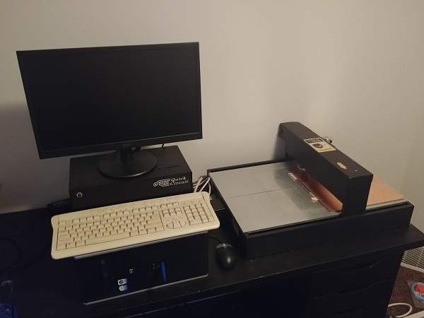
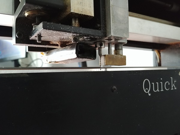
This machine uses a basic brushed DC motor for the spindle. The height is controlled by solenoid, it is either up or down. The depth of cut is controlled by a dial next to the spindle.
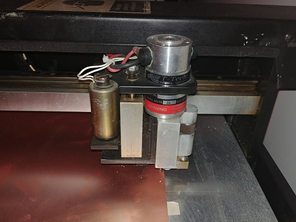
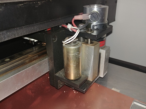
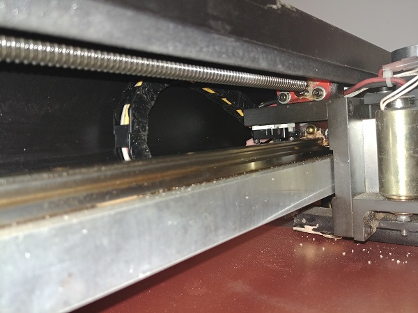
The machine uses precision guides and ball screws.
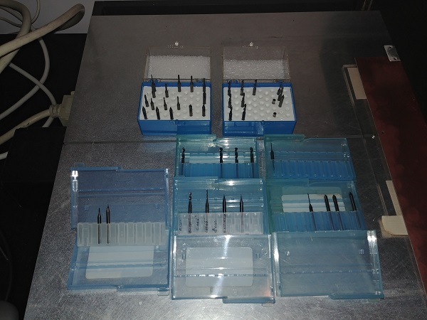
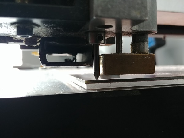
This picture on the left shows the slot that is used to pin the boards. To the right shows the engraving cutters and drills I received, all are carbide.
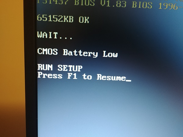
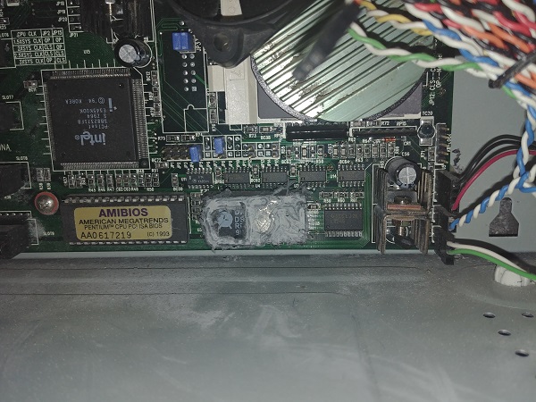
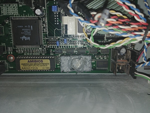
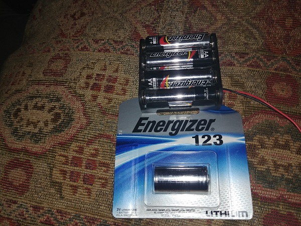
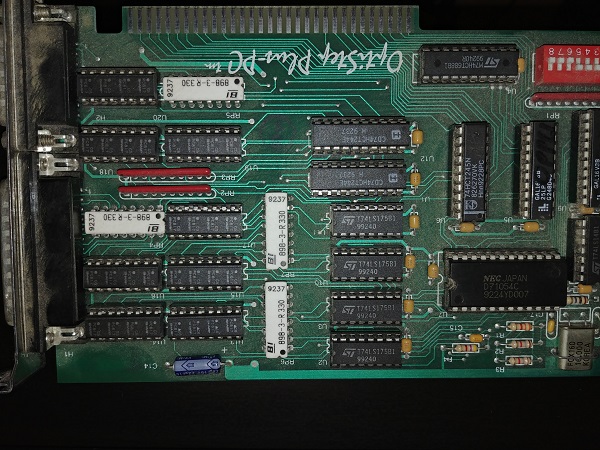
When I switched the machine on I expected to be making boards within an hour, not so. It told me that the CMOS battery was low, this refers to the real time clock for the BIOS. All computers remember the date when powered down thanks to a little chip called the real time clock. All of the settings in the BIOS are also stored in SRAM meaning that if power is lost, these settings are lost. There is a small lithium battery inside of the real time clock that supplies a minute amount of power to it and the BIOS. So when a computer is powered down the real time clock continues to run, this is why the date is remembered.
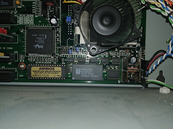
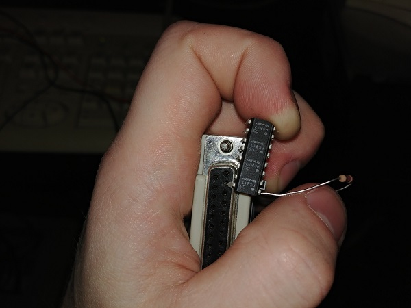
The majority of modern computers will have an accessible coin battery, but these older computers had a shelf life, the battery was sealed internally. One fix is to replace the real time clock with a new one, not an issue if you have the correct de-soldering tools. I instead chose to use an engraver and cut away the case to expose the battery.
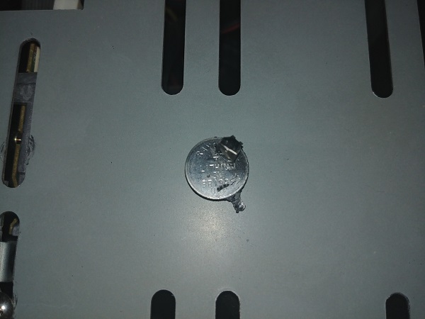
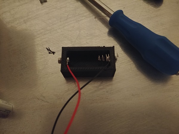
Here is the small lithium battery removed.
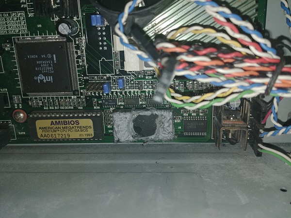
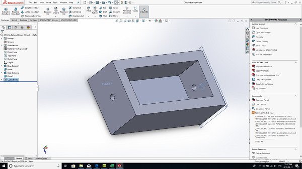
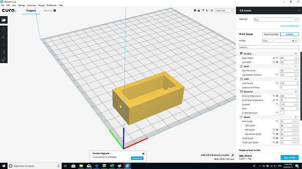
I designed and 3D printed a holder for a new battery.
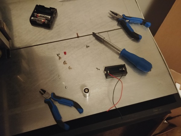
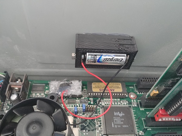
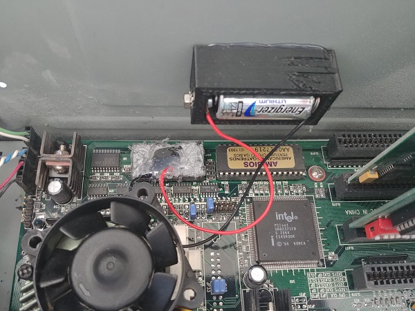
The battery holder was glued inside of the case and the wires soldered to the existing terminals in the real time clock, a dab of hot glue to stop the wires from coming loose.
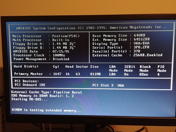
I setup the BIOS settings and booted the computer.
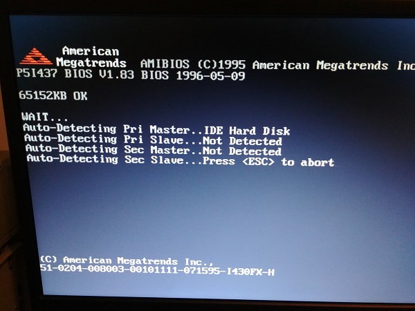
The computer is dated at 1993 and the time of writing this page is 2019, this thing is 26 years old. The BIOS was updated in 1995. This computer was certainly at the end of it's era by looking at the specification, but two years prior this would have been a high specification.
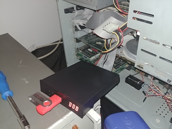
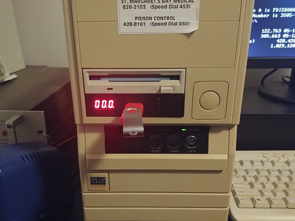
The biggest problem with the computer is that it would only accept floppy drives. I managed to find a floppy emulator that would read a USB as a floppy disc.
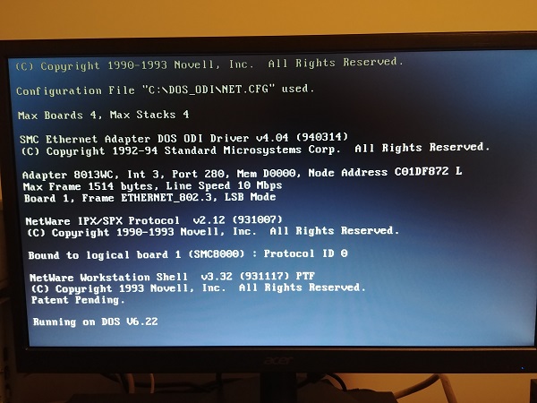
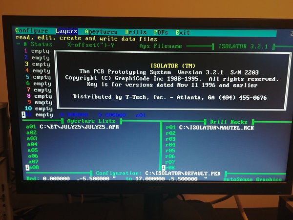
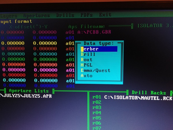
The computer is running DOS version 6.22, I believe this was the final version before the windows operating system. I literally had zero experience but I managed to work out a few commands. I placed two gerber files on the USB and verified my drive emulator was working properly. I then ran a program called "Isolator".
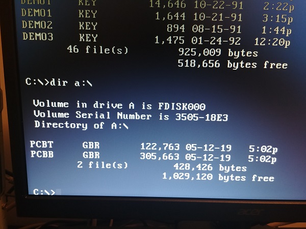
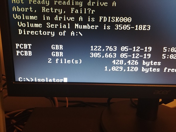
This software can be used to create designs for the circuit board, it can also be used to load existing files. The main purpose of this software is to convert these files into G-code for the mill to operate.
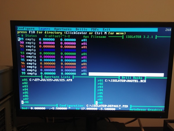
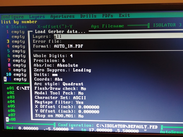
I loaded the gerber files into the software.
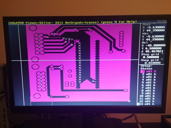
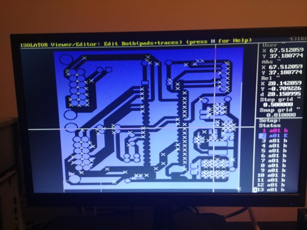
Here shows the top and bottom of the board. Due to the specification of the graphics card it misses out a lot of details unless zoomed in.
It took me quite a bit of time to figure out both the isolator software and that to run the mill. I set my PCB design software to imperial but did not realise that it only output metric gerber files, once I learned this I ran the mill. I quickly found that the mill was extremely slow when running from files not written in the isolator. Between every line of G-code the mill would pause, it was far too slow for me. So I did some investigating into a better control system. I quickly found that the parallel printer port was not standard and could not be connected to a modern computer, I couldn't use the driver board from the old PC either.
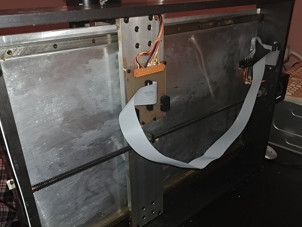
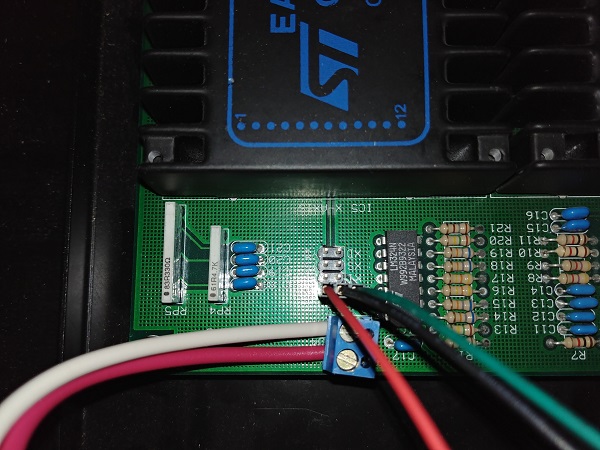
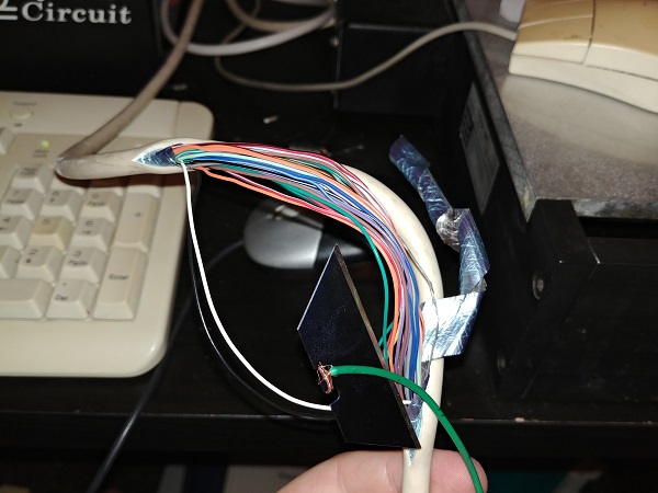
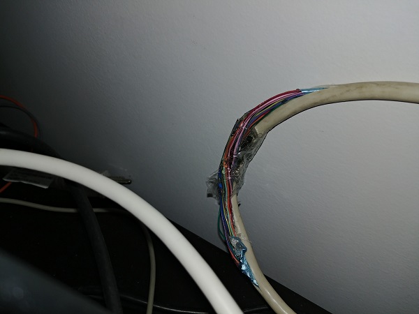
Luckily all of the opto-couplers on the board were placed in sockets and easily removable. I opened up the control box to see how it was constructed, luckily there were some jumpers that I could use to test the pins. Overall I had to modify the wires in the printer cable itself, I also had to use a couple of opto's for the spindle and solenoid drive.
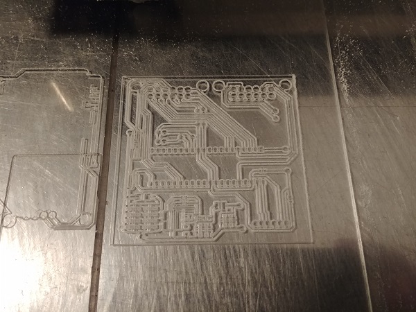
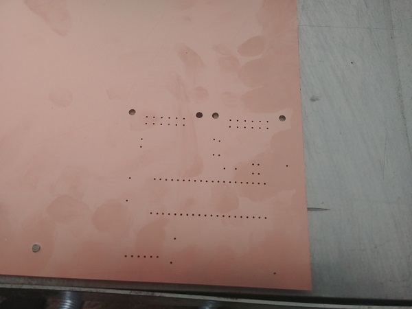
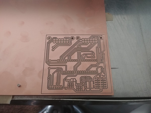
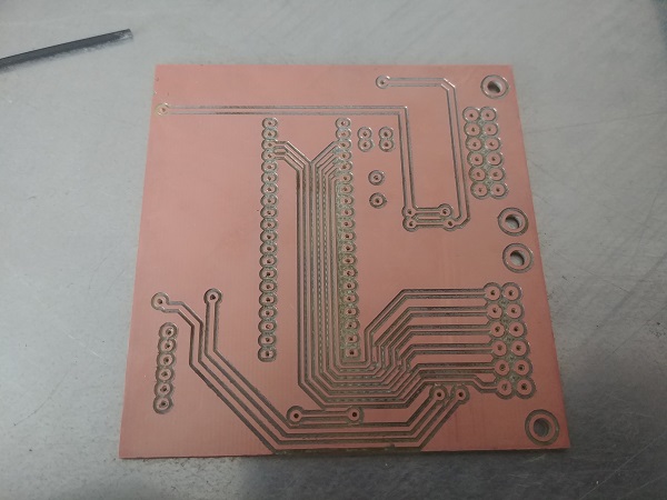
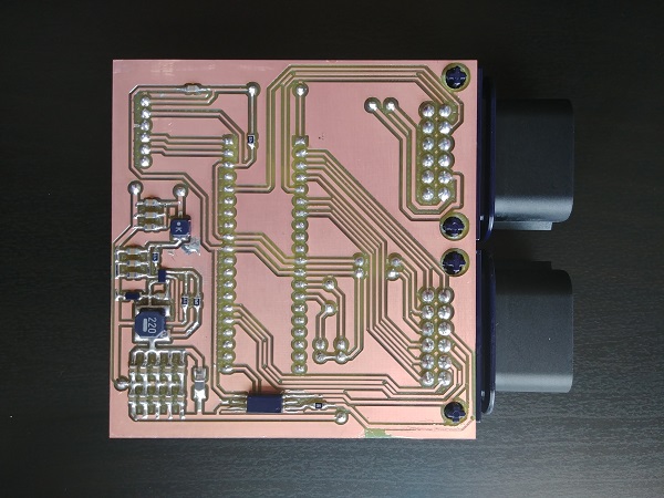
Thankfully it was a success. The left pattern was milled using the old computer and the right using the new computer. The difference is that one is nowhere near complete and the other complete, both took the same amount of time.
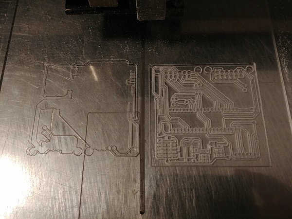
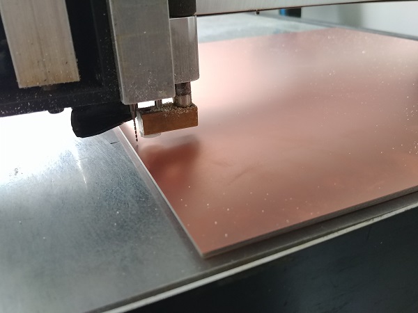
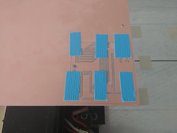
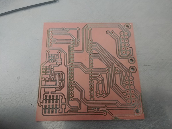
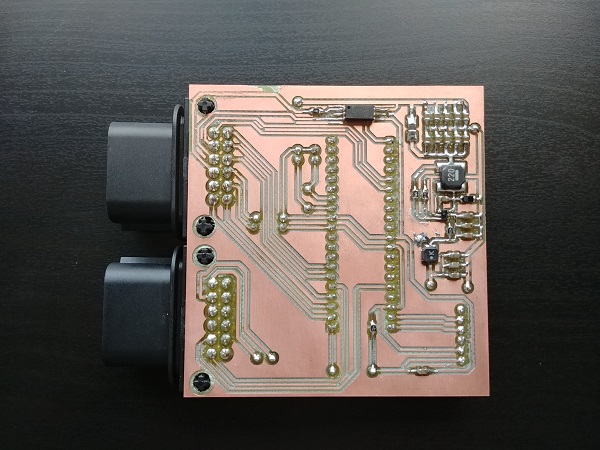
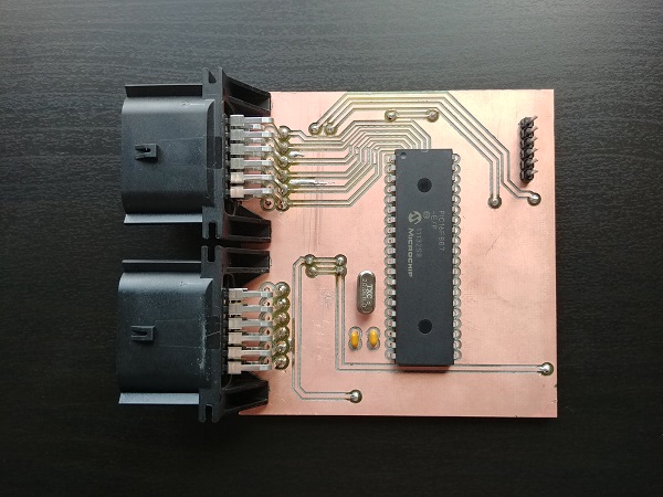
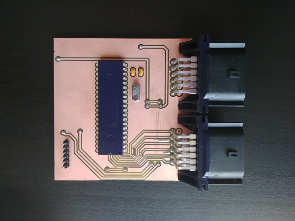
Here are a couple of pictures of a board being made.

Overall I'm really happy with this machine considering how cheap I got it. There are a few things I would like to improve however. The Z-axis is operated via a solenoid, it is either up or down. The issue is that I don't believe the spindle motor spins fast enough when drilling some of the holes. I think either a stepper on the Z-axis or a much faster spindle motor is required, probably the latter.
The machine is very well built, it's heavy, sturdy and accurate. Please check through my other projects as I will go into more detail on how I design and make circuit boards on this particular machine.
Hello, if you have enjoyed reading this project, have taken an interest in another or want me to progress one further then please consider donating or even sponsoring a small amount every month, for more information on why you may like to help me out then follow the sponsor link to the left. Otherwise you can donate any amount with the link below, thank you!