Siemens CNC Lathe Repair
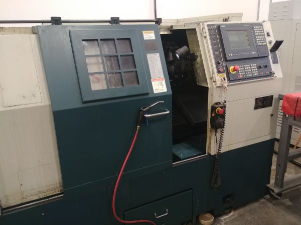
Currently where I work one of the CNC lathes catastrophically failed (September 2019). The machine was able to reference the axis's but soon as the spindle was enabled it would throw an alarm. The alarm I believe translated to an over-current situation, likely an IGBT failure in the spindle drive. I checked around in the back of the machine to see if anything looked suspicious, one of the cables to the motor was loose. I tightened the termination but the issue was still there. I was employed as a machinist so the work was left for a service technician.
In the end the boss would not take any responsibility and decided we should just keep switching the machine on until it worked. The machine was switched on, referenced and then as soon as the spindle drive was enabled there were a series of about 10 bangs. Consequently the room filled with the smell of magic smoke, clearly a big component failure. I killed the power to the machine and told no one to touch it. Again time passed and the boss decided it would be best to replace the machine, already getting behind on manufacturing I proposed I would fix it.
I remembered I have been in this situation many times before, I am paid to machine yet I have gone beyond to fix something. In every single situation I have saved a great amount of time and money, I have never been compensated for it. I then thought that ultimately I want to be repairing machines in the future, so I could add this to my portfolio.
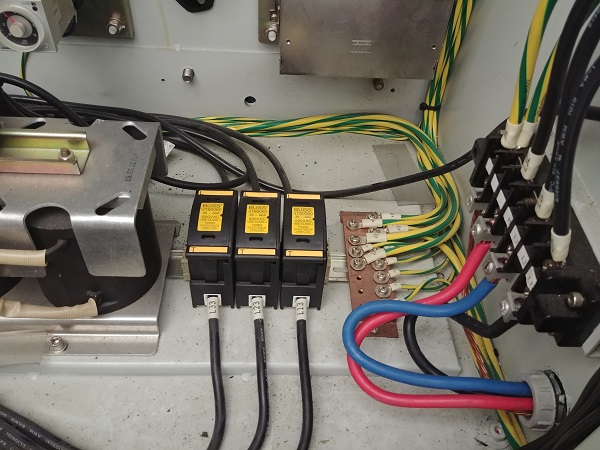
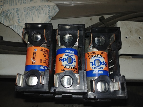
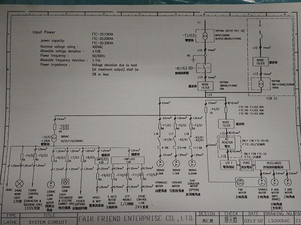
The very first thing I did was make sure the machine was switched off at the wall, and then physically checked there was no power present. When troubleshooting the repair of a machine it is always recommended to check all the fuses first. Quite often the issue can be traced back to where a single fuse has failed. There were three main fuses from the supply to check. These particular fuses have an indicator to show if they are ok, even so it is a good idea to check them with a continuity meter. They were all ok.
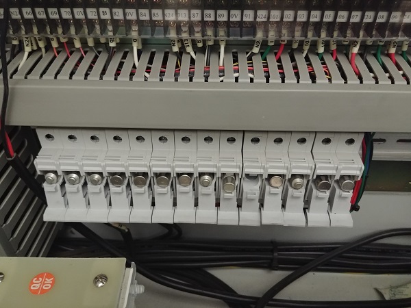
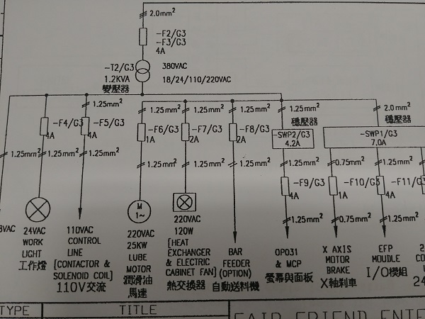
The next set of fuses to check are those for all of the systems. Even though I'm pretty certain what has failed in the machine it is still wise to check over all other possibilities. Considering that the main fuses had not blown and I suspect it is the spindle drive that has failed doesn't quite add true. I like to open all of the fuse holders, the ones that are good I close and the bad ones I leave open. Here there are two bad fuses, one holder without one present.
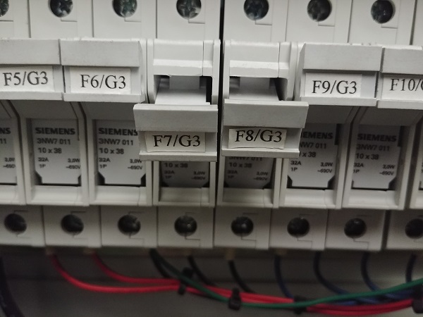
Looking through the electrical diagram I find that the missing fuse is for the bar feeder which this machine does not have. The second is for the heat exchanger which keeps the inside of the machine cool and low on humidity. I do know this unit has never worked since I've worked here, the policy is not to repair or maintain until something breaks. So I can conclude that all is good here, although the heat exchanger is probably what led to premature failure of the machine. I will replace the 2A fuse because the unit does work.
The fuses were all ok but I knew that the spindle drive had failed and it could have damaged the power supply unit. The spindle drive clearly smelt of burnt electronics and had soot extenuating from the cooling vents. I removed this module because I wanted to check what else may have failed and why this drive may have failed.
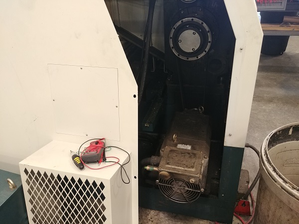
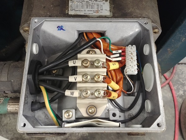
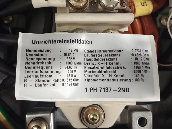
The motor windings would be the first place to start on why the drive unit may have failed. One of the connections to the motor was loose which could have given false back-emf readings to the control leading to it's failure. Knowing this I should still check for other possibilities. The first thing I checked was the insulation resistance, this was good with a basic meter, ideally a high voltage meter would be used. A little piece of paper was found inside the motor termination case with all the details on. What I needed to be looking for was the winding resistance, I don't really know German but I can work out what some of it means by the values.
R - Stander kalt (Resistance - Standard cold)
R - Laufer kalt (Resistance - Running cold)
Stander streureaktanz (Standard Reactance)
Laufer streureaktanz (Running Reactance)
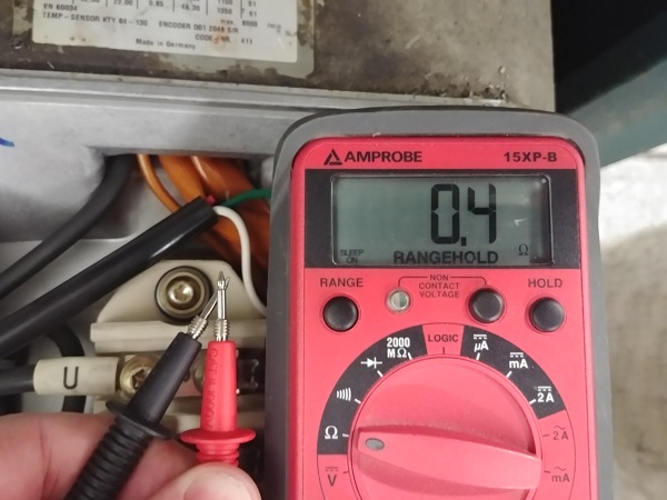
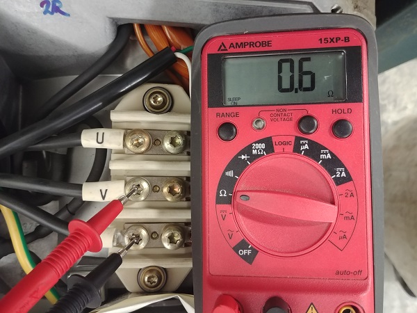
I have a cheap resistance meter but it will give me an indication to if anything is wrong. So first I checked the probe resistance, this meter does not allow me to zero. I then checked the resistance between all of the windings, each winding came out as 0.2 ohms. The standard resistance should be 0.15 ohm, I was happy with this result.
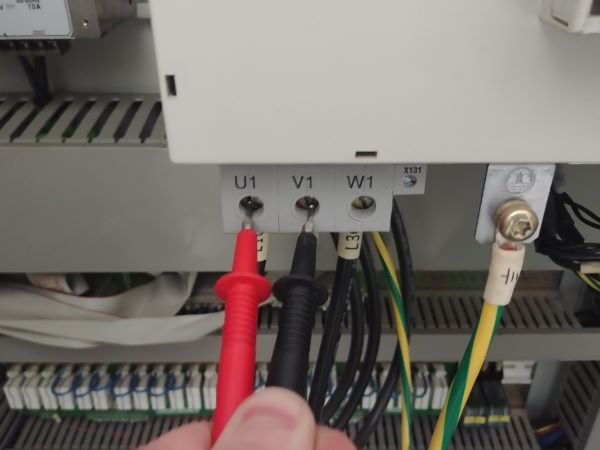
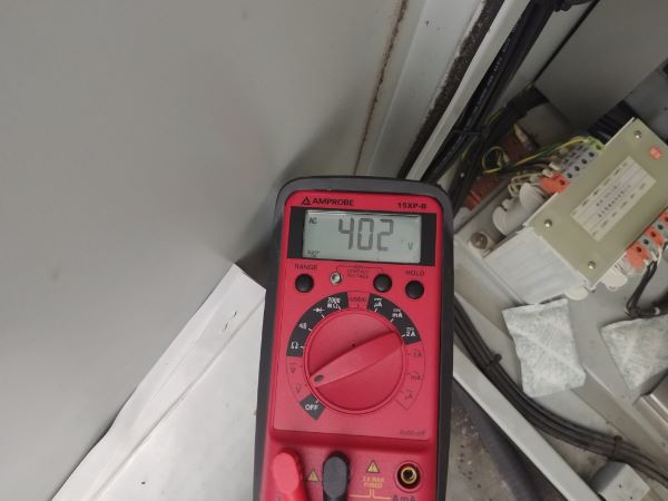
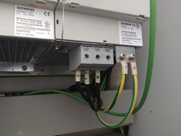
I was happy that the motor was ok, the next step was to check the power supply as this could have been damaged too. I switched the power on and checked the voltage between the phases to the DC control supply. Each phase had a similar voltage so I was happy the supply was ok. Since the supply fuses were ok it was wise to check this supply as the reactor could have failed internally.
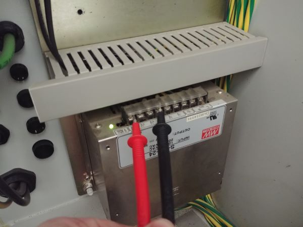
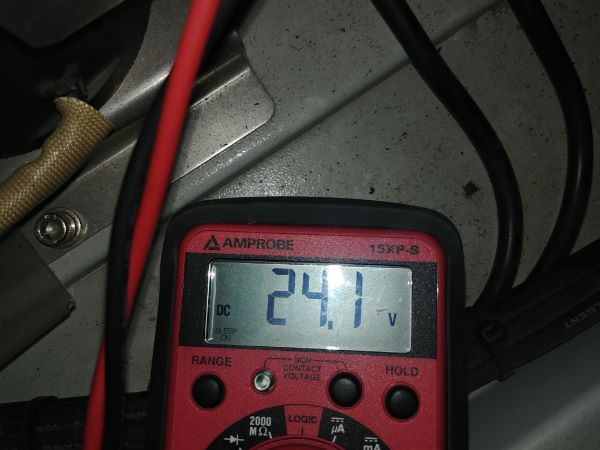
I then checked the main control power supply to make sure this was ok, it was.
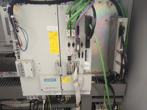
I opened the electrical manual to see how the main supply was controlled as I have no experience or the diagnostic tools for a Siemens machine.
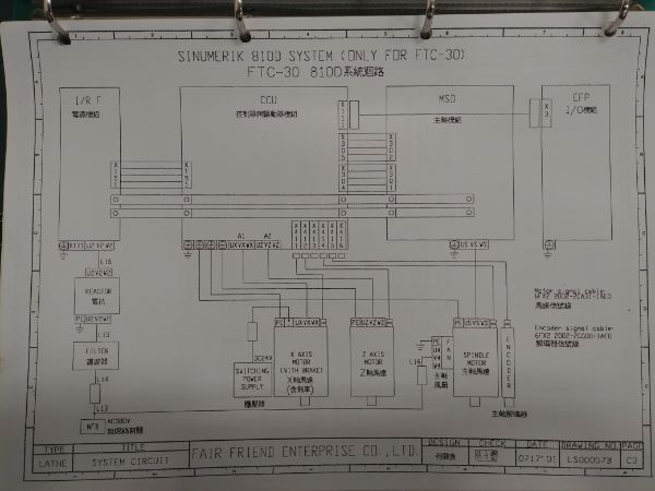
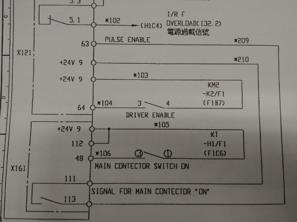
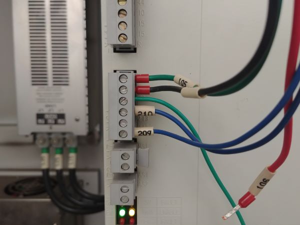
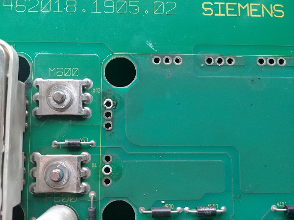
I found the main supply was labeled as the I/R F module, this was the alarm present on the machine before it failed. I could see there was a possibility of two connections to manually override and switch on the main supply. Block X121 connects to a relay in block X161 so I can assume that block X121 is dependant on block X161.
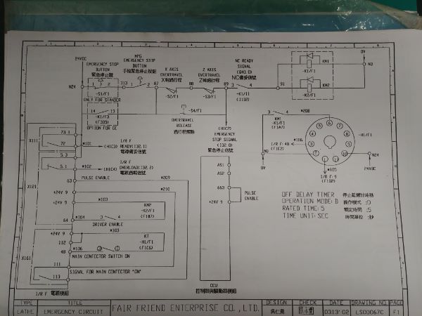
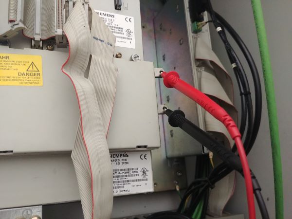
I connect a voltmeter to the supply bus and then a wire to the +24V terminal on the control power supply.

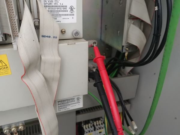
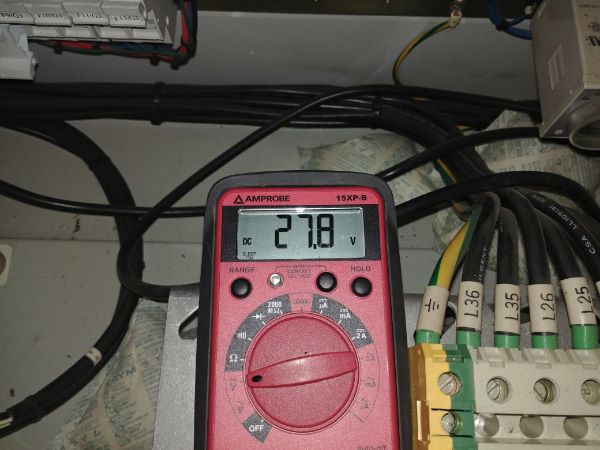
I can see from the diagram that terminal 48 in block 161 should switch on the supply. The bus voltage is currently reading just under 28V, I know this will likely be around 600 Vdc.
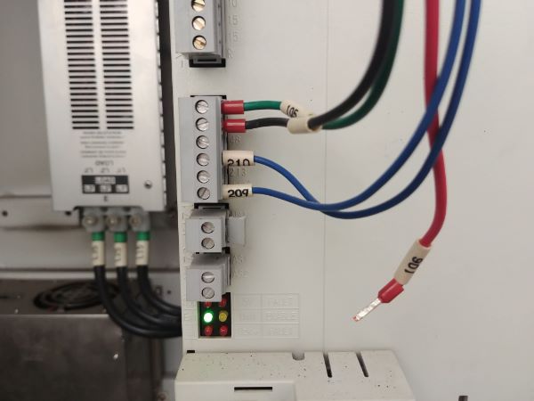
I remove the wire from terminal 48 and connect +24V to override the supply, this should switch it on.
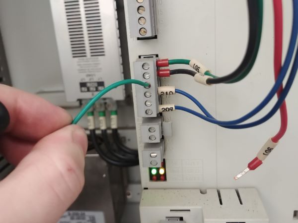
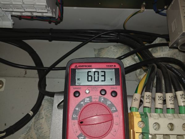
The supply clicks and the bus voltage rises to 600Vdc.
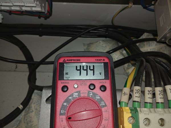
I then remove the wire and the supply switches off, the bus voltage slowly discharges. It is best to leave the meter connected to the bus until it reaches a safe voltage, this could be fatal if touched.

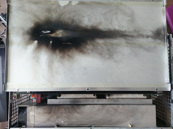
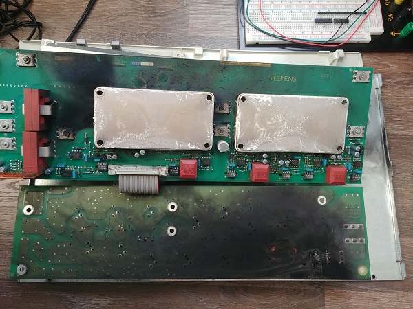
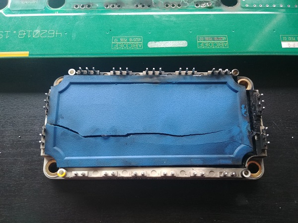
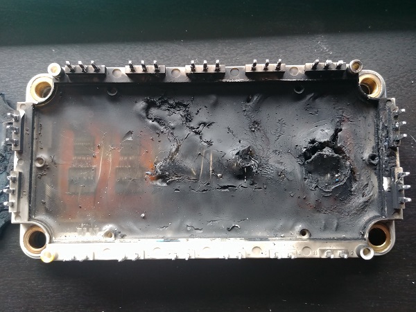
Everything else in the machine looked good and it checked out electrically. Everything pointed towards the spindle drive so I decided to open it up. Clearly something had gone wrong in this drive, the heat had broken through the plastic protection.
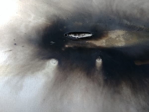
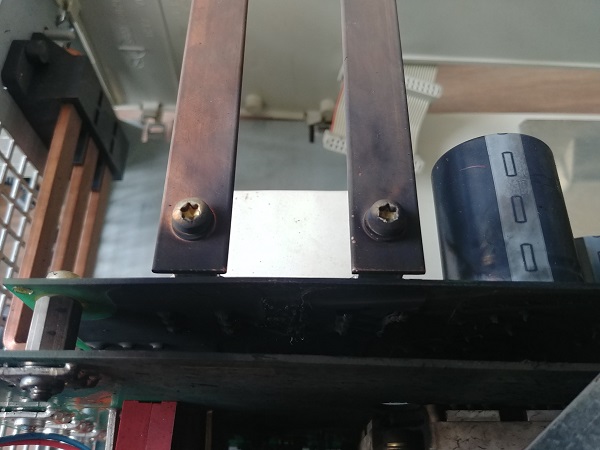
I wondered if maybe the bus bar had broken through the film and shorted on the case. If this had been the issue there would have been visible burn marks on the opposite side of the case and potentially holes through it.
I imagine it would have been a failed IGBT which often short when damaged. The short will have subsequently caused the tracks to burn up and the carbon will have increased arcing, hence the multiple bangs when it failed. If the IGBT had just failed and nothing else happened to the board then I could have repaired it. The issue is that when a board burns there is a build up of conductive carbon, the only way is to remove this section of board and thoroughly clean the rest. I decided that it would not be worth my time repairing this board, however I will check what failed, how I would repair it and the cost at the end of this page.
In all I concluded that only the spindle drive had failed. I did not have the diagnostic tools to check the axis drives but these worked before and did not look to be damaged. I found a new drive online for $2000 CAD which is considerably cheaper than it would have cost from the manufacturer. A week later I received the new drive in the original box.
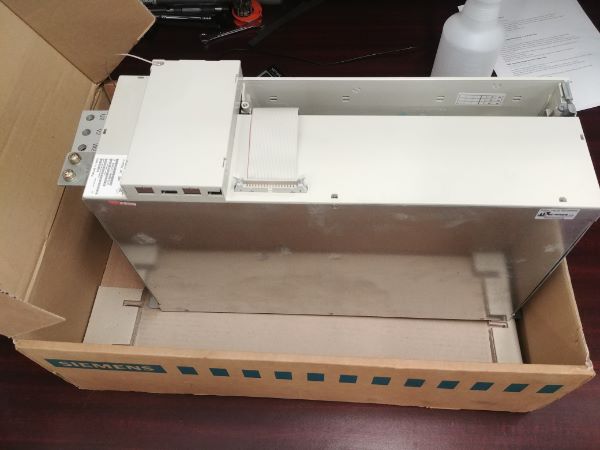
I installed the drive making sure that all the terminations were tight.
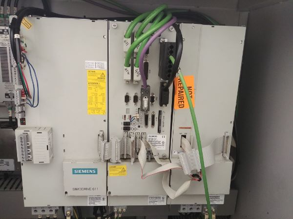
I switched the machine on and it worked perfect.
Spindle Drive Repair
It is fairly uncommon to repair things on a component level as it is often faster to replace the whole module. Let's say for example that this machines parts are obsolete and to replace the whole drive system is far too costly. The repair of this board may then be worth it, even if it cost thousands of dollars.
So as seen above the failure was quite catastrophic causing carbon deposits to be strewn everywhere. There is an industrial process called "sputtering" which is the vaporising of metals into gases, these gasses then coat surfaces with a thin deposit of metal. When arcing occurs on board tracks it can in fact vaporise the copper and leave a conductive coating on all components. So the very first step and by far the most important is to clean the board down. There are many different methods but I think a nylon brush, soap and water is the best method. The issue with using solvents is these can soften the circuit board silkscreen and cause these metallic particles to embed themselves.
Normally when a fault occurs with something electrical it will never fix itself, the problem is most people don't believe this. This drive would have been quite a simple repair if it had not been turned on and off several times. The problem is that a simple component failure eventually led to a catastrophic failure. Each and every component needs to be thoroughly cleaned, both the top and bottom. The larger components such as the IGBT's have a very small gap beneath them, the only way to properly clean these is by removing them.
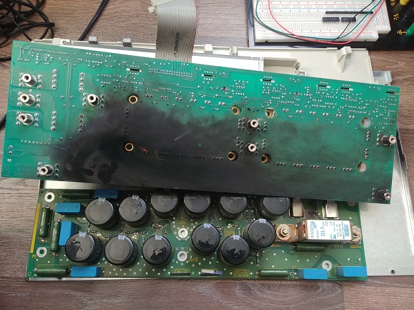
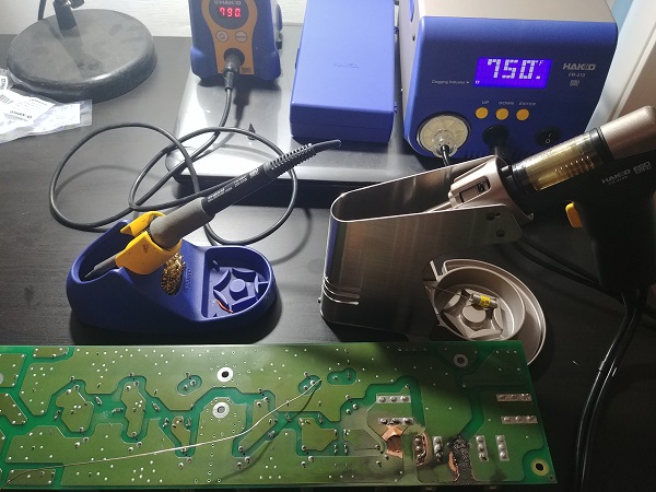
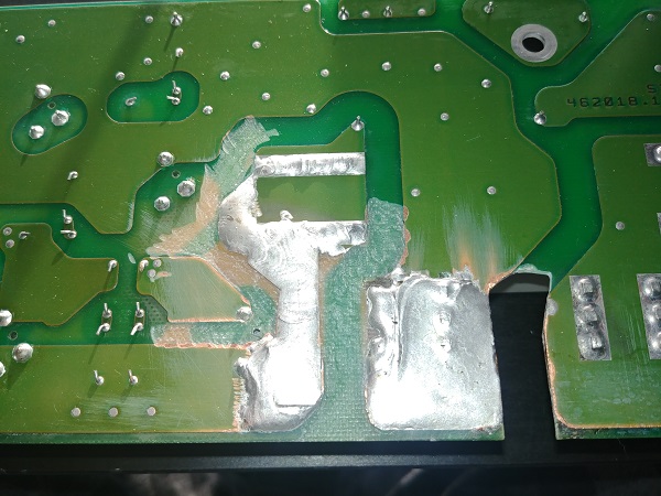
Here are several pictures showing the extent of the damage. It is clear that the deposits cover all sides of both boards and that all of this is caused by a burnt track. I wondered if it may have been the bus touching the casing but there is simply not enough damage to the head of the screws.
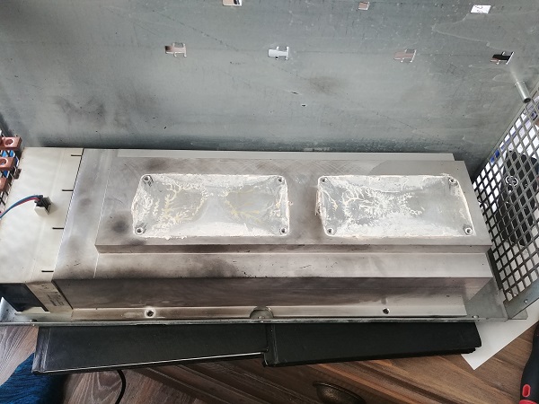
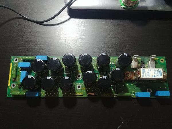
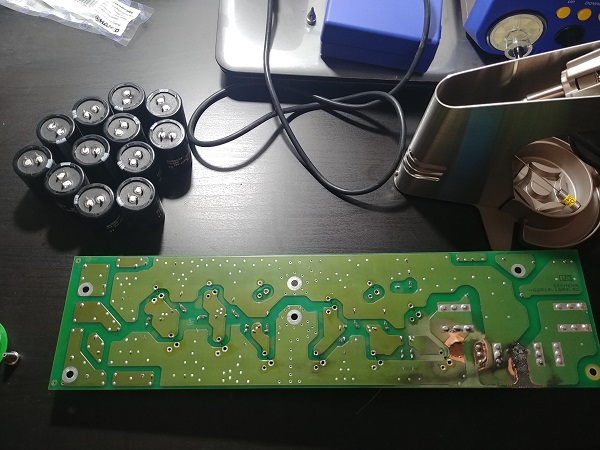
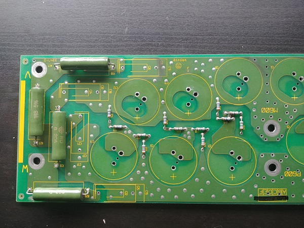
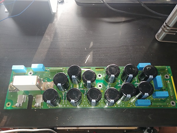
I first gave both of the boards a very thorough scrub in soapy water to see how bad the damage was. It was likely an IGBT module that has failed, if this was the case then I could clean the underneath when it came to replacement. It is not an easy task to replace these modules and either requires a desoldering station, or destruction of the component. I chose to work through this constructively as I needed to repair the board, so I would first start with the power supply. Here below is that board.
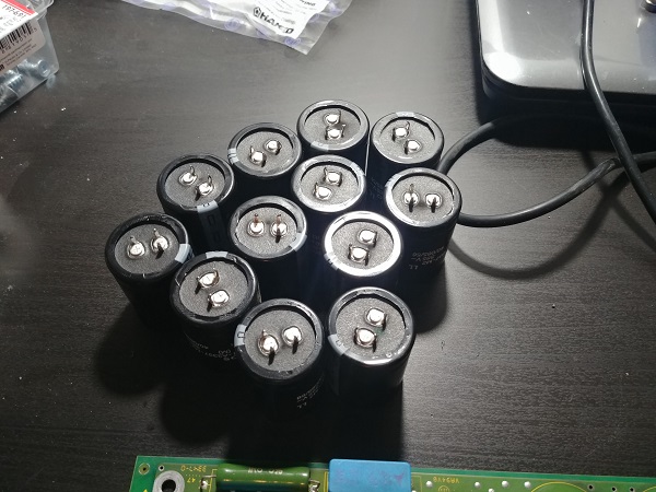
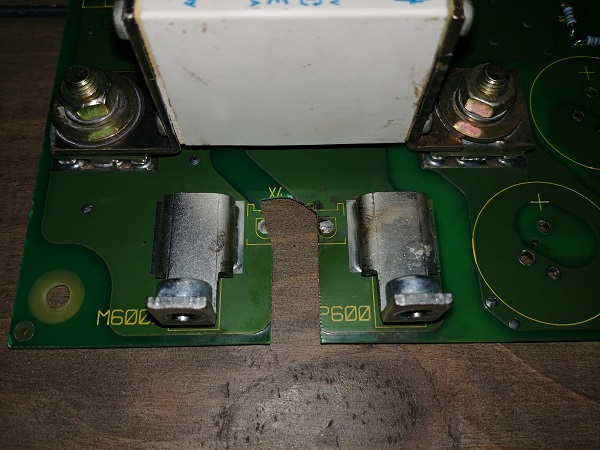
It is very simple in construction as there is a set of capacitors that smooth the supply, also known as filter capacitors. These capacitors are rated at 400 and tied in series pairs, therefore capable of 800V, the supply being 600V. In between the capacitors are small bleed resistors which discharge the capacitors when powered off. Also on this board is a set of snubbers, these remove transient voltage spikes from damaging the IGBT's. A snubber consists of a resistor and capacitor, a basic low-pass filter, each snubber is connected to the IGBT output and to both ground and the supply. For a three phase drive it will mean it consists of six snubbers, hence six blue capacitors and six of the large green resistors.
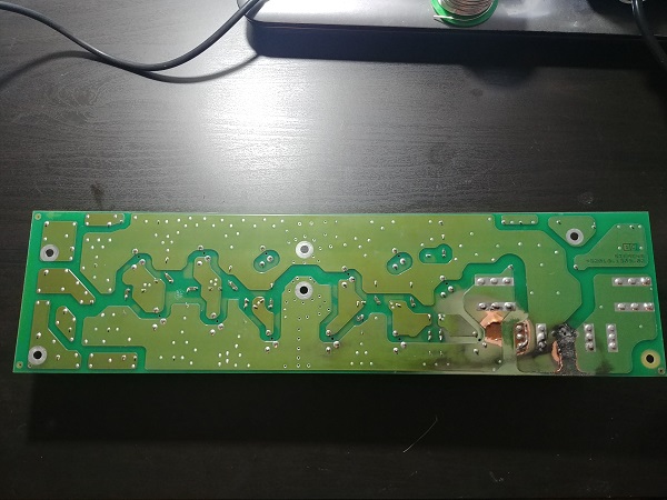
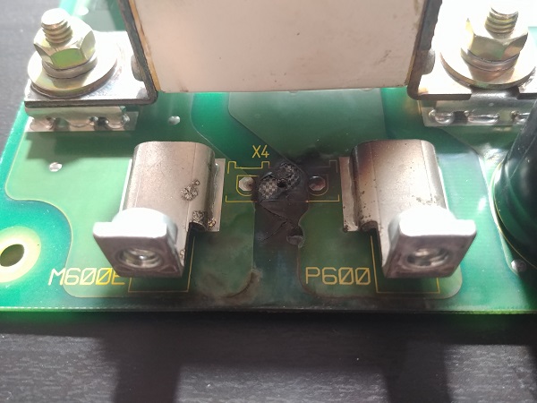
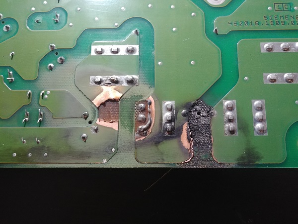
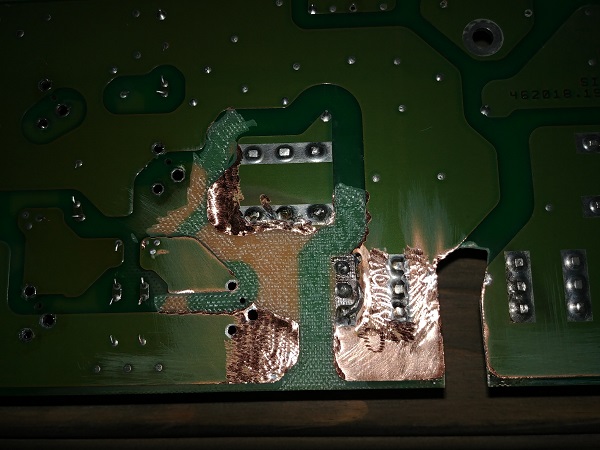
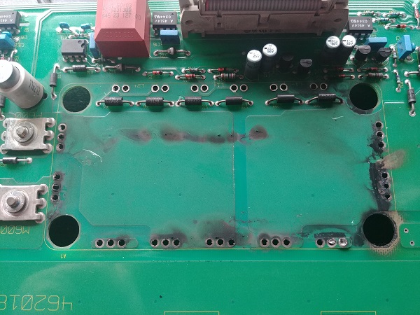
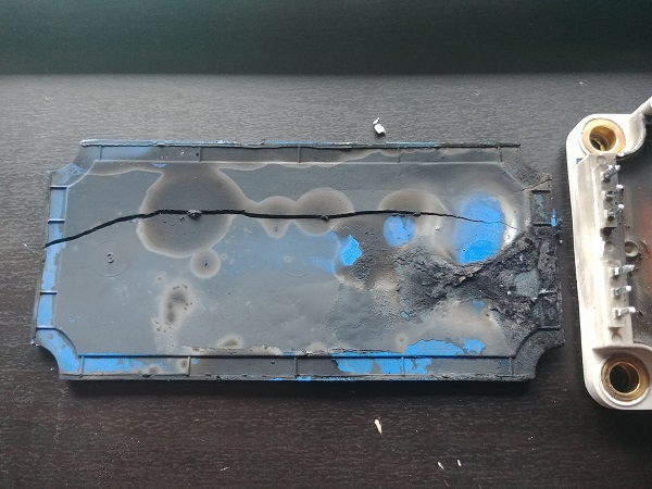
The only damage and where all of the deposits had come from was a space between the supply bus. The supply bus comes externally from another power supply. On the back of the board we can see a broken track and a burnt space between the bus bars. I believe a short would have occurred causing the track to burn up and arc, the plasma generated from this will have caused arcing between the bus. This burnt area was just an aftermath of the damage caused by a different failure. Since the board was burnt up it would not be wise to use it as this carbon is conductive. To reuse this board I would have to cut this section out.
To reuse this board I would have to remove all of the components and test them. Removing the components has to be done in this case because deposits may be underneath them, high voltage is more prone to arcing. If a failed capacitor had caused this then it would have been likely the capacitor would have catastrophically failed too. All the capacitors looked to be in great condition so I knew it would be doubtful. It is not a wise idea to test components in circuit as others may affect the readings. The ESR reading is quite often the test of a capacitor to choose as it shows if it's shorted or open, this reading is affected by the other capacitors in the circuit but still can be an obvious indicator. Since I will be removing the component I can check the capacitance, the ESR and charge it to maximum voltage to check leakage. All of these tests will also check to see if a capacitor is likely to fail soon, even if it may be functional.
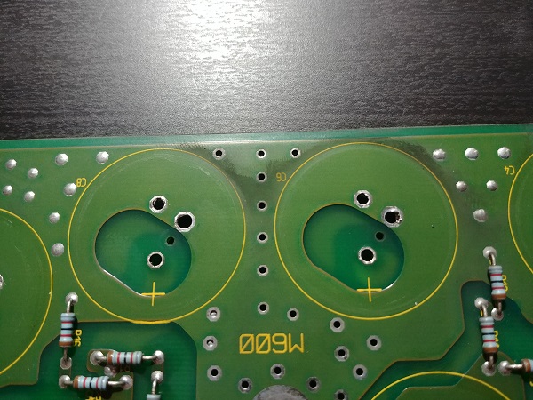
I used a vacuum desoldering station to remove the main electrolytic capacitors.
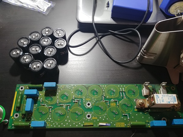
Even though I cleaned the board you can still see some deposits around the circumference of the capacitor. I found no deposits under the capacitors but that is something I could not have guaranteed, I can also safely test the capacitors now.
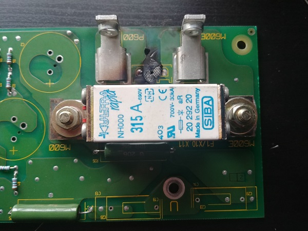
I also chose to remove the snubber capacitors since these cannot be cleaned underneath, I am confident I can clean the underneath of the rest of the components. One last component to check on the board is this fuse, it is supposed to be very fast acting to prevent this type of damage. I checked the fuse and it is still good, maybe this is a design flaw.
All the burnt sections of board need to be removed. The really bad section has to be cut out but the surface burns on the rest of the board can be ground down. I also grind away some of the silkscreen so I have somewhere to solder to. The tracks are repaired using copper sheet, it is best to go thicker than necessary. Once I have finished with this board I will coat the repaired areas with an insulating lacquer as a precaution.
There are a couple of methods for testing capacitors but the best is to test it's ratings out of circuit. Charging the capacitor to it's rated voltage and then measuring the leakage is the best test of whether a capacitor is good, bad or on it's way out. If the leakage is too high then the capacitor will likely fail before it reaches rated voltage. Next would be the capacitance rating, if it's not within tolerance then it is bad, capacitance over tolerance is ok too.
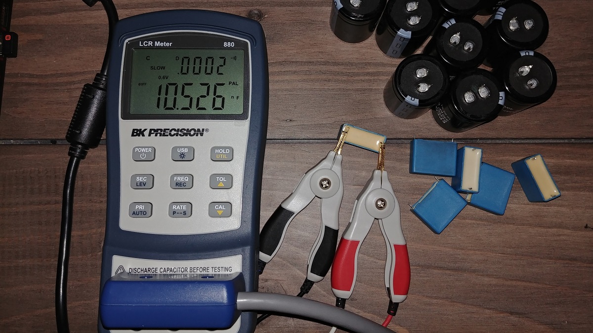
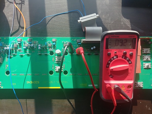
The most common method of checking a capacitor is by using an LCR meter. A higher end model will check capacitance, ESR, Q level and dissipation factor at many different frequencies. The dissipation factor best determines the life of a capacitor as it includes both ESR and reactance in it's calculation. ESR / Xc = DF , 1/Q = DF. Dissipation factor is also known as the loss tangent. In basics the higher the loss the more energy the capacitor has to dissipate, also higher temperatures lead to shorter component life. Here shows my meter below testing the electrolytic capacitors.
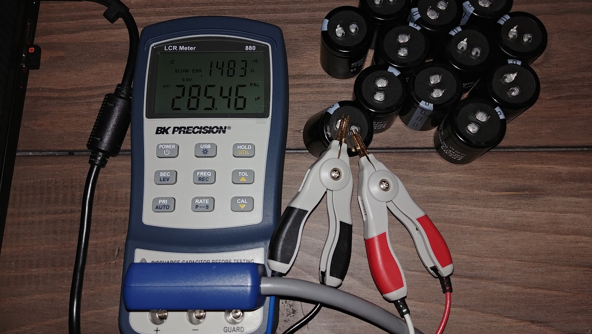
These particular capacitors are EPCOS part B43501-A3337-M2 / 385V at 330uF. I was quite amazed to find this data sheet but it's great because I can see if the capacitor is within specification, or getting ready to fail.
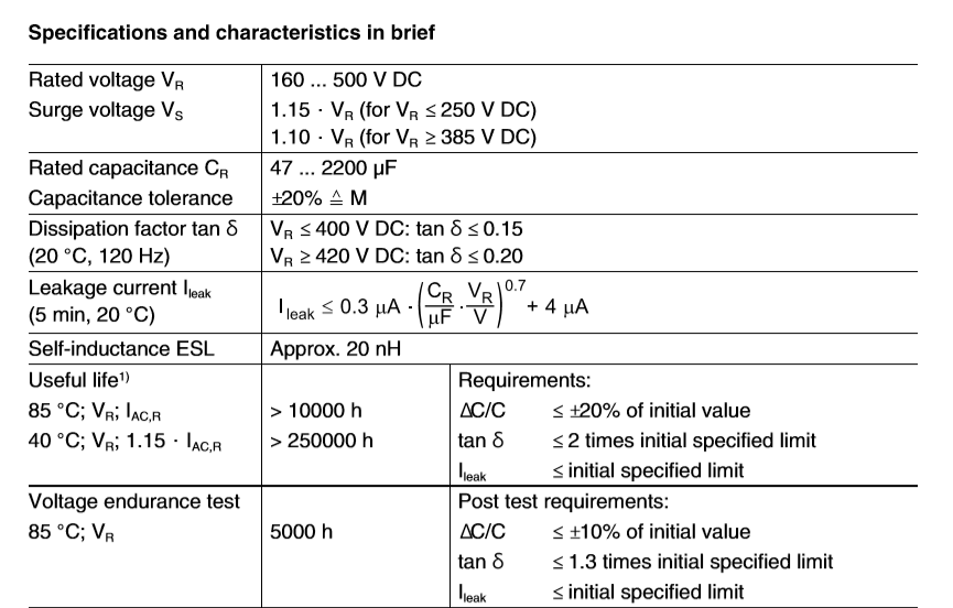
Here is a table of the results obtained, ESR at 100Hz, Dissipation factor at 120Hz. The ESR is well below the design value and are all very close to each other. The dissipation factor is dramatically below limits and again all are very similar. The capacity is towards the low end of the tolerance, not great but all are in tolerance. These capacitors have a very long service life, they are still in excellent shape and do not need to be replaced.
| Component | ESR mohm | Dev. % | Diss. Fact. | Capacity uF | Dev. % | Pass / Fail |
| Design | 200 | 0.15 (0.3 max) | 330 | |||
| 1 | 148 | - 26% | 0.029 | 279.1 | - 15% | Pass |
| 2 | 145 | - 27% | 0.029 | 285.7 | - 13% | Pass |
| 3 | 148 | - 26% | 0.029 | 280.9 | - 15% | Pass |
| 4 | 149 | - 25% | 0.029 | 281.4 | - 15% | Pass |
| 5 | 148 | - 26% | 0.029 | 282.9 | - 14% | Pass |
| 6 | 147 | - 26% | 0.029 | 282.9 | - 14% | Pass |
| 7 | 147 | - 26% | 0.029 | 281.2 | - 15% | Pass |
| 8 | 148 | - 26% | 0.029 | 280.9 | - 15% | Pass |
| 9 | 145 | - 27% | 0.029 | 286.7 | - 13% | Pass |
| 10 | 149 | - 25% | 0.029 | 279.4 | - 15% | Pass |
| 11 | 144 | - 28% | 0.028 | 283.3 | - 14% | Pass |
| 12 | 146 | - 27% | 0.028 | 279.4 | - 15% | Pass |
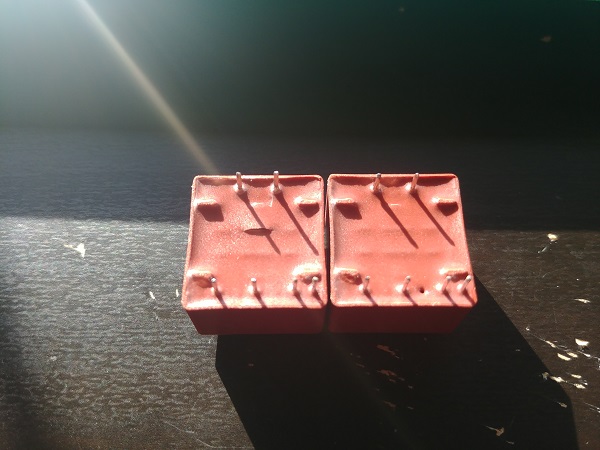
The snubber capacitors will be a metallic film type which are very robust and unlikely to fail, regardless I will test them. I could not find the exact part number but managed to find the equivalent from the same manufacturer. These capacitors are polypropylene, 1600Vdc, 10nF. I took this extract from the data sheet, the dissipation factor is very low on these capacitors, again this is what I will test. The code on the top also says 10n K, which is 10nF at a 10% tolerance.
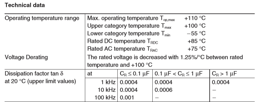
These capacitors measured to the top end of the dissipation factor tolerance at 10kHz but the rest were ok. Normally when a capacitor starts to fail these values are completely out of specification, decimal place differences.
| Component | Diss. Fact. 1kHz | Diss. Fact. 10kHz | Diss. Fact. 100kHz | Capacity nF | Dev. % | Pass / Fail |
| Design | 0.0004 Max. | 0.0004 Max. | 0.0010 Max. | 10.00 | ||
| 1 | 0.0003 | 0.0004 | 0.0003 | 10.13 | + 1% | Pass |
| 2 | 0.0002 | 0.0004 | 0.0003 | 10.56 | + 6% | Pass |
| 3 | 0.0003 | 0.0004 | 0.0003 | 10.17 | + 2% | Pass |
| 4 | 0.0003 | 0.0004 | 0.0003 | 10.34 | + 3% | Pass |
| 5 | 0.0002 | 0.0004 | 0.0003 | 10.25 | + 3% | Pass |
| 6 | 0.0002 | 0.0004 | 0.0003 | 10.52 | +5% | Pass |
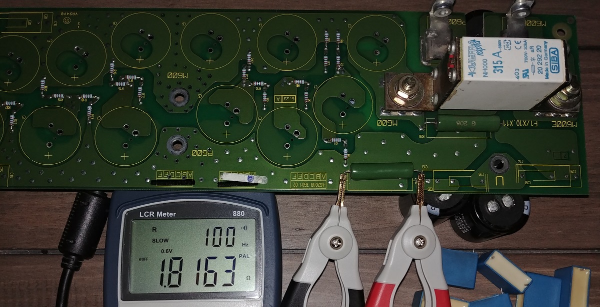
The snubber resistors have also been disconnected from each other with the removal of the capacitors, these can be tested on board. Normally when a resistor fails it will burn up, they are very reliable and to this date I have never seen one fail open circuit. Regardless I will test each resistor to ensure it is in tolerance. I will add that because these are snubber resistors and running at high frequencies they will be low inductance, either metal film or carbon film. Using wirewound resistors would be a very bad choice due to their inductance.
I reassembled the board along with the repaired track. I would normally coat the new track with an isolating lacquer to reduce exposed copper, but it is more likely I will scavenge parts from it instead. Overall this board is now repaired and perfectly functional, it can be placed back in service.
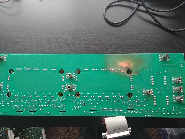
Now that the power board is repaired it is time to see what failed on the switching board. After giving the board a wash there is quite a prominent heat spot present. I knew I would have to remove both of the IGBT modules to clean away the carbon deposits, this would also give me the opportunity to test each individual transistor. I used a desoldering station on all of the pins, the solder on both of these boards required reflowing, I suspect a higher temperature solder was used.
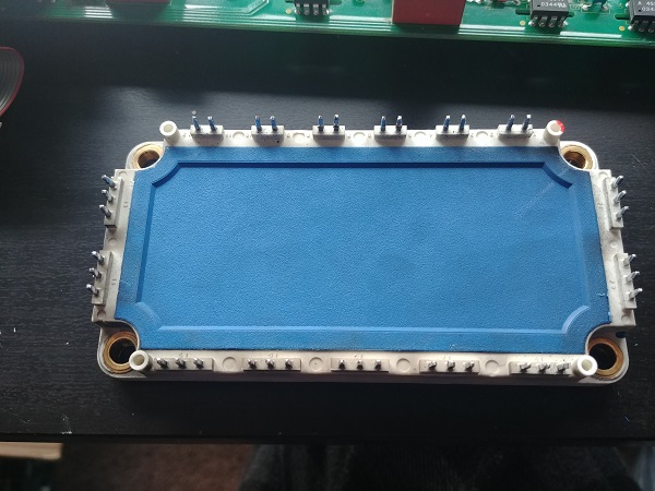
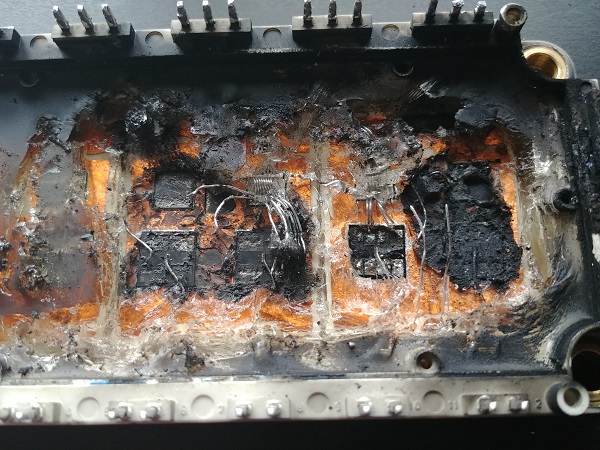
I removed the first IGBT module and lifted it's protective cover. Inside can be seen that there are six separate IGBT's, these are paired up for this application. Covering these components is a jelly like substance, maybe this is used due to thermal expansion as I would have expected some kind of epoxy.
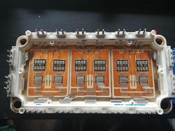
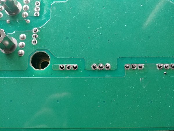
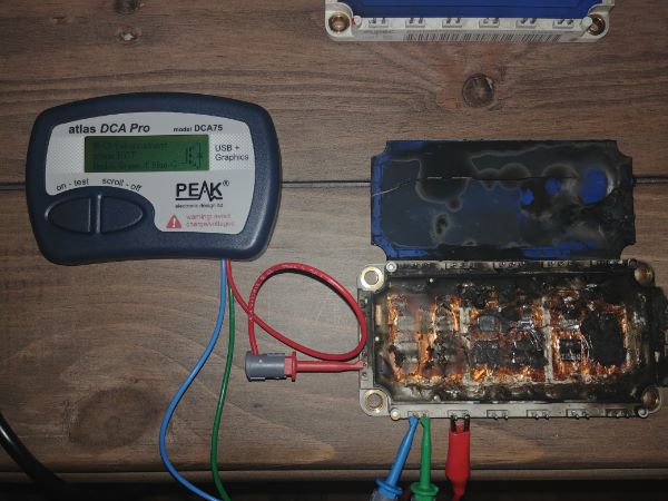
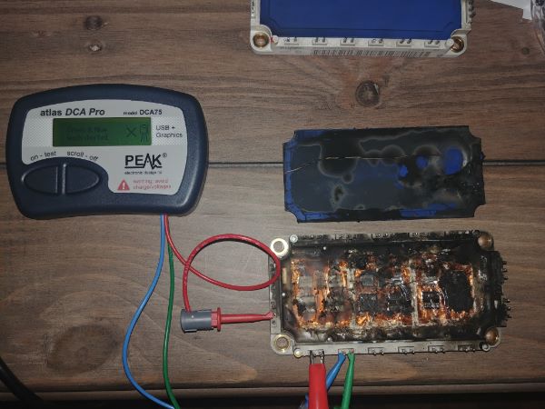
I removed the second IGBT module, there is clearly more carbon deposits under this one. A couple of the pins were also badly damaged to the bottom right, I even lifted the track slightly when removing it.
It is quite clear that this module is the culprit for failure.
I removed the jelly to see the extent of the damage, two thirds of the module is toast. Almost all IGBT's and MOSFETS will fail in a similar way, they tend to short between all of the legs. The issue is that this creates a dead short and causes quite extensive damage, the fuse should have prevented this amount of carnage however.
These IGBT's are fairly easy to find but come with quite a high price tag. This project is just to explain the steps of how I would repair this drive, I actually have no use for it so it's a little hard to justify the money. I will make some stupidly low offers online and see if I can jump on a deal. In the mean time I will explain how to test the other IGBT module as it's really easy to do, just in case I need two modules. The IGBT in simple terms is an electronic switch, failure will cause it to short between the collector and emitter. So if the gate is tied to the emitter then the IGBT will be in the off state. If a voltage is applied between the collector and emitter then the current flowing should be zero, the current limited with a resistor. If there is current then it has failed. A second test is to apply a voltage to the gate to see if the IGBT switches on, current flows though the collector.
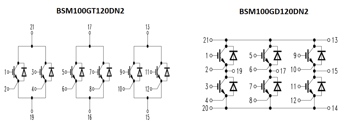
A much better alternative is to test the IGBT with a meter to ensure it is within specification. So before I test the IGBT I should first check the pin diagram. Here are two very similar part numbers, the one one the left applies to this drive, that on the right does not. If there was just a single module on the board then it would be assumed to be the part on the right, a full 3-phase H-bridge. Since there are two modules you'd expect 3 transistors per module, or three pairs in this case.
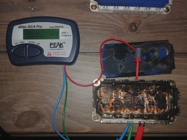
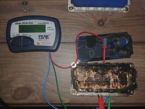
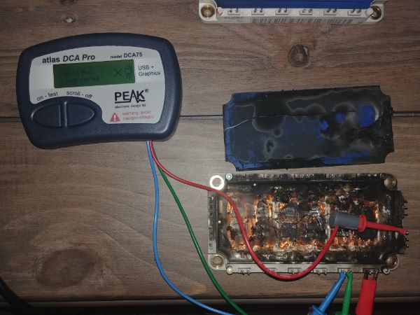
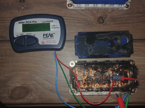
In order to test this module I must test each transistor individually, to do this I must tie the gate to emitter on one transistor pair while testing the other. I picked up this meter which will detect many different semiconductor types and then analyse the saturation voltage, the gate switching voltages and will even plot these on a graph. This meter is intended for smaller components and will not accurately read large IGBT's such as these, however it will tell me if the IGBT is good or bad. Another thing I like about this meter is that I can connect the leads to any leg and it will diagnose what each leg is and what the component it. So for example the module that looks to be in good condition had each transistor checked, it told me every time I was measuring an IGBT.
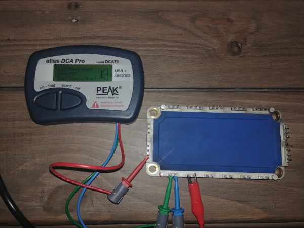
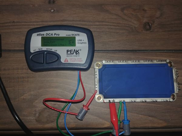
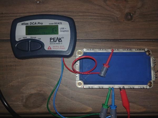
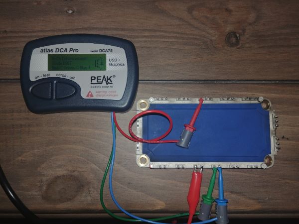
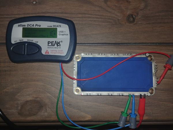
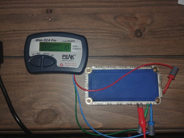
Checking the damaged IGBT was a different story. I didn't realise the pictures may be a little hard to read. So the first transistor checks out good. The second tells me there is a short between the blue and green lead, this is the gate shorted to the emitter. The third, fourth and fifth detect a short between the red and blue, this is a short between the collector and the gate, (and I would imagine the emitter too). The last picture does not even detect a component present. There are very small wires connecting the semiconductors to the component legs, it is these that exploded, I'm surprised there was even a component measured at all.
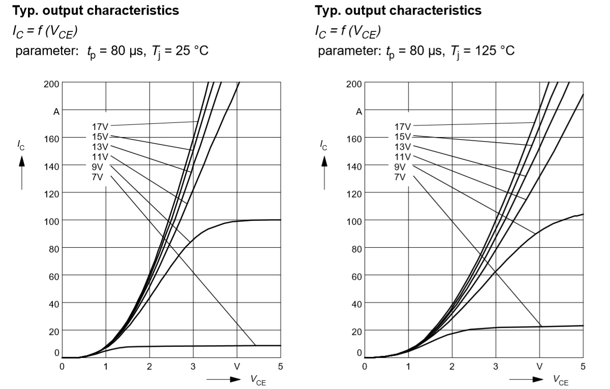
At the front of the data sheet it tells me that the Collector-Emitter saturation voltage is 2.5V, 25 deg C at 100A. That is the voltage drop across the collector and emitter, this is the majority of the power that is lost. So 2.5V at 100A, 2.5 x 100 = 250W. So the saturation voltage is a big factor in determining how much heat the module will dissipate, that exponentially increases with current drawn and module operating temperature. The data sheet says that 680W of power can be dissipated per IGBT at 25 deg C operating temperature, note that it means 1 IGBT pair. In total the module can dissipate 2kW of heat before it fails, that is the IGBT junction produces more heat than can be thermally conducted.
In the data sheet will be a couple of graphs, as shown below, taken from the data sheet. The meter I used to test these IGBT's says that the Vsat is 0.43V at a current draw of 20mA. As can be seen from the graph this value does tie in at the bottom of the scale, however overall it is not a true representation of what this IGBT is rated at. I will add that an IGBT will often completely fail resulting in a short between all legs, they do not fade like an electrolytic capacitor.
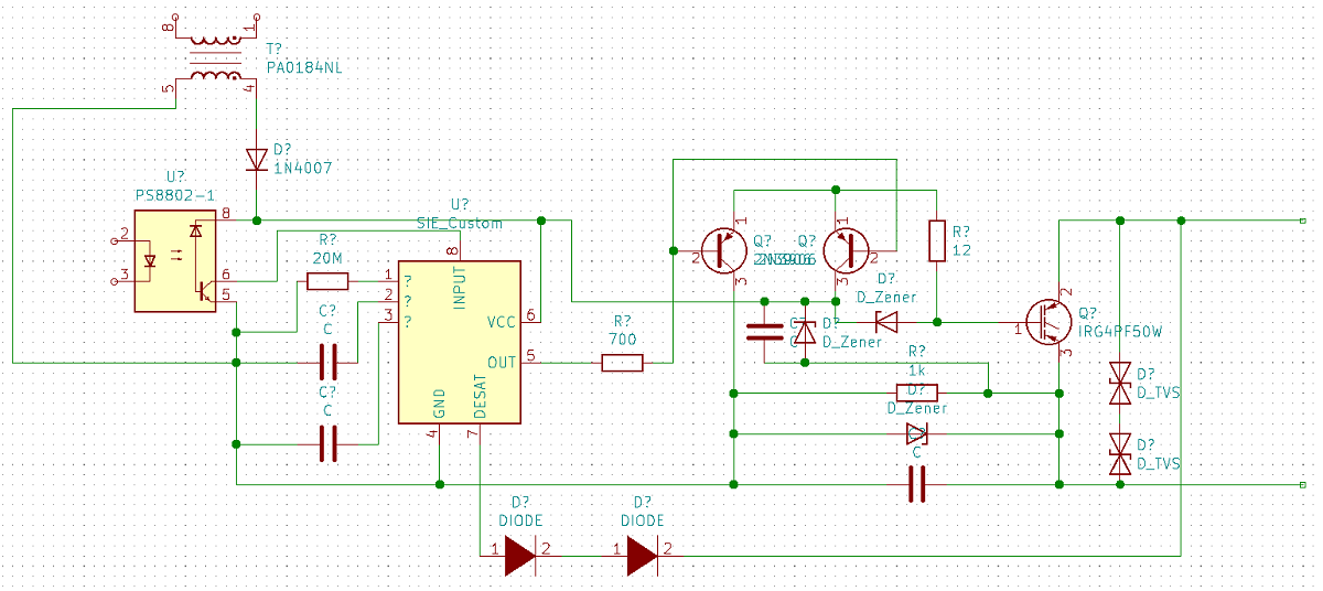
Since the first IGBT is good it means I only have to search for another, hopefully I can get one super cheap. Now all depending how the drive circuitry has been built will depend if it got damaged too as the gate will have likely shorted to the emitter, or even worse the collector. There are quite a few different ways to go about this. In simple terms there should be an input, some kind of isolation, then an IGBT driver circuit. If voltage applied to the input causes the gate driver to change state then we can say it is ok. Since this is a three phase drive it will mean there will be six IGBT's (or six pairs in this design) and therefore six drive circuits. It is very common practise to copy all of the drives, therefore all six drives will usually have the same circuit, although do not always assume, check first. I spent some time following the traces and came up with a circuit diagram for these drives, I also drew a diagram for the whole drive.
Here is the diagram for the drive circuitry. I will note that these part numbers do not match that on the drive, they are just so I could draw a quick diagram.
I often find the most difficult part of repairing something like this is finding all the necessary data. I believe that a few of these components were only built for this specific manufacturer and because of this there is no documentation. The main driver chip has a part number beginning with SIE, as in Siemens, I could not find any data on this part. I can work out from the above diagram what these components are and what each legs are doing, the issue is replacing these if I have to. The first place to start is with a driver that is most likely ok, that is those that were driving the undamaged IGBT module.
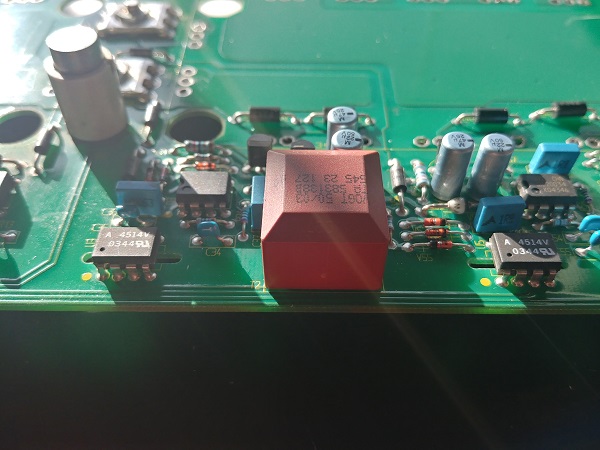
I also noticed that one of the transformers supplying a damaged IGBT had a bulge in the top of it.
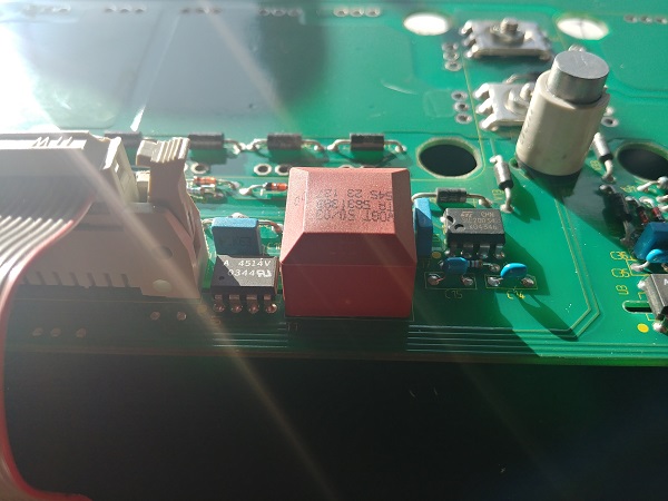
I removed the transformer to find a crack beneath it. Comparing it to one of the other transformers concluded that the output windings had shorted. These are just basic high frequency ferrite cored transformers, they are what supply power to each drive. I also decided to check each of the drives, only three out of the six were functioning.
Since the chips were specialised and I could not find anything similar online I decided to go no further with the project. I could not source IGBT's any cheaper than $200 CAD each, again far too expensive when I don't have an application for them.
Conclusion
I really wanted to get this board to a repaired, functioning standard. Unfortunately due to the shear cost of an IGBT module I cannot justify fixing it as I don't have an intended application for the end result. It is likely I'll harvest the components for another project. Hopefully this project shed some light on how a drive such as this would be diagnosed, tested and repaired. It is often a lot cheaper and faster to replace the whole drive which I did in this case.
Hello, if you have enjoyed reading this project, have taken an interest in another or want me to progress one further then please consider donating or even sponsoring a small amount every month, for more information on why you may like to help me out then follow the sponsor link to the left. Otherwise you can donate any amount with the link below, thank you!