Vacuum Mould Modification - 4
Recently at work we decided to get into the compression moulding business and found out that we really didn't know what we were getting ourselves into (January 2018). We were advised on what machine to buy based on our moulds and prior experience (zero). A few weeks after receiving the machine I was struggling to make any decent products on it, some came out great and others were full of air pockets. It wasn't until we got the machine that I started doing some research on the subject as my main job was a machinist so I had no time. After doing the research I realised that the machine should have a vacuum enclosure which is standard and that we should have a pre-forming machine for the raw unprocessed material.
In the first two projects I proved to my employer that having a vacuum around the moulds would greatly improve the result of the product, I mean if all the machines out there use it then there must be a reason. In the third project I got a much more powerful higher flowing vacuum pump and used the same mould cap design. I ran into an issue that the vacuum was so strong that it pulled the rubber through the lines. This project will replicate what a machine with a built in vacuum system would work like. There is no possible way without a serious amount of modification to set this machine with the actual vacuum enclosure, there simply is too much money since I would not have the capabilities to machine the stuff myself.
Design
This was my first original design long before I modified the mould to accommodate a vacuum, between this and now we have lost over a month of productivity, this could have been avoided unfortunately. The design is rather crude since it was a quick doodle on paper.
I then drew a mock up in Solidworks, here is the assembly.
Machining
In the previous few designs I had incorporated some caps on the moulds and a sealing tube to be passed over the middle. These caps required me to modify the moulds that we previously knew had worked before and it tied one of our production machines for a day. The issue is that the caps and the tube are in close proximity to the mould. The vacuum was so strong that it pulled rubber up the hoses and between the sealing tube resulting in the mould getting stuck together. I tired my best to pull it apart but I could only get around 30 tonnes of pulling force out of the press. All of this is what led me to the design I have now.
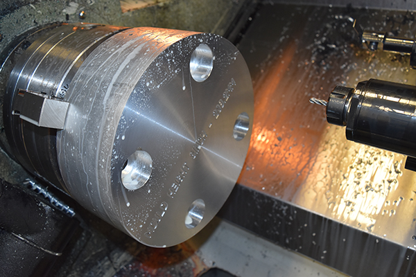
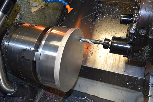
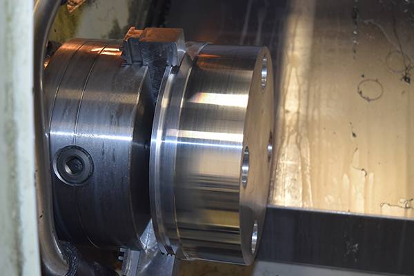
I acquired a piece of 10" aluminium solid round bar at a length of 3, 3/4". I needed to use solid bar for the piston to better transfer heat, I chose aluminium because it is a great conductor, easy to machine and light weight. I first started out by facing it off to set the work offset.

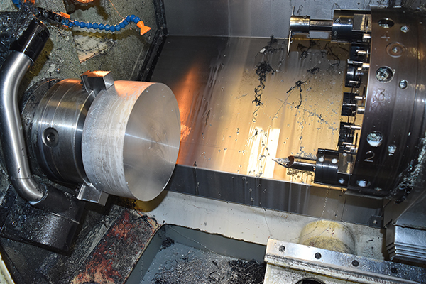
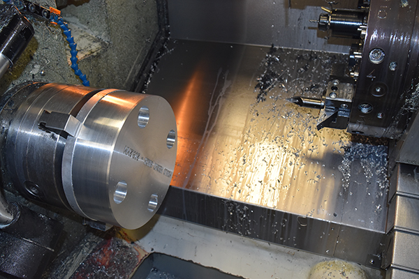
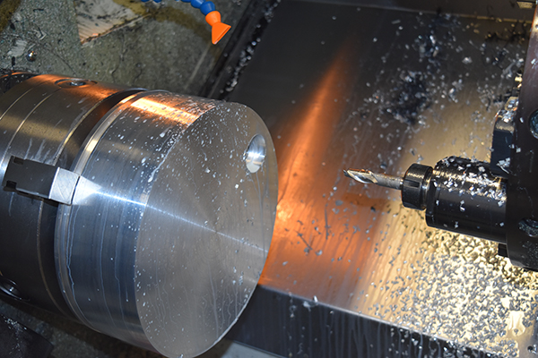
I had some serious issues when drilling this part at first. There is a simulated milling mode and also a spindle orientation which allows holes to be drilled at specific points using the C-axis. The problem I found is that as soon as my drill touched the material it caused the chuck to move, I eventually found the "M" code which actuated a pneumatic brake on the spindle. I then wrote out a program to mill out some pockets over the holes, the pockets for a nut and a socket to pass.
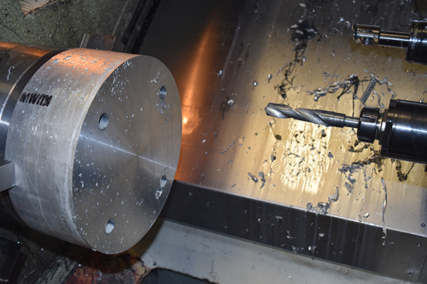
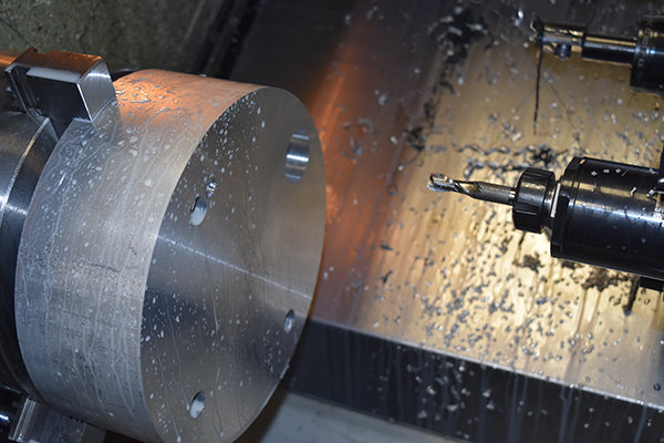
A total of four M16 bolts should easily be strong enough, they only have to hold the pull of the vacuum. I managed to make a little mistake as when using the simulated milling the machine reads the spindle orientation offset (which was 80), I could not apply the spindle clamp under this mode so chose to use spindle orientation (same as M19) which completely ignores the spindle offset, so my original hole was 10 degree different to the final holes. I managed to face enough material off the face to almost cover the mistake, I just wonder why the spindle offset is ignored (and why I didn't check and set it at zero at the beginning).

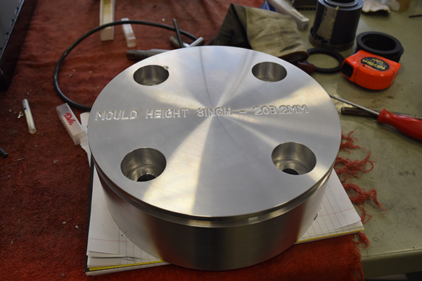
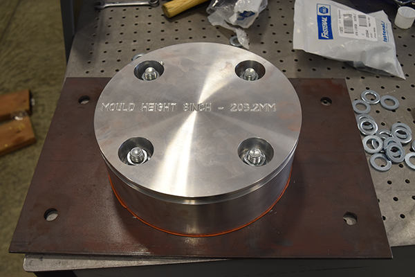
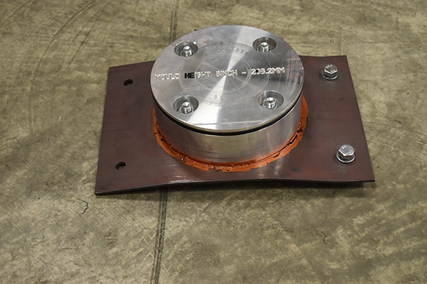
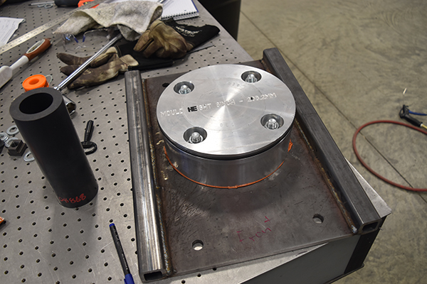
I placed a ball nose cutter in the machine and engraved (Mould Height 8" - 203.2mm). If the mould height is less than 8 inches then the sealing tube will hit the top platen before the piston touches the mould. I set the outside turning tip zero point and also the "X" offset.
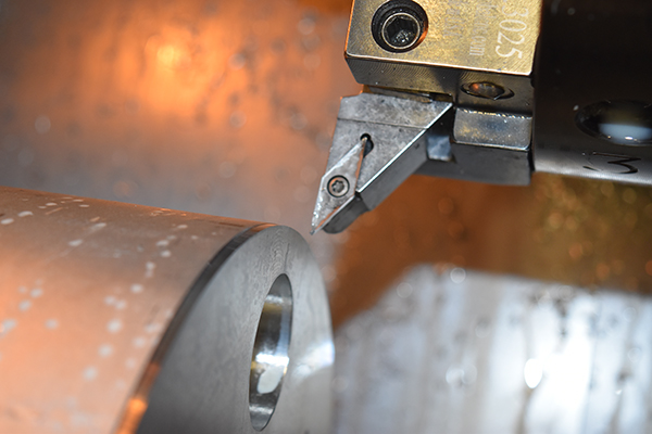
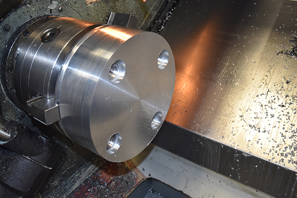
I turned the piston to 253mm, the bore is 254mm. A vacuum is one atmosphere of negative pressure, that means it only has to seal around 15 psi of pressure so a clearance of 0.5mm should not allow the O-ring to extrude. I cut an O-ring groove, I really should have done this last.
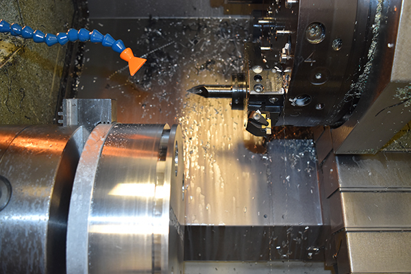
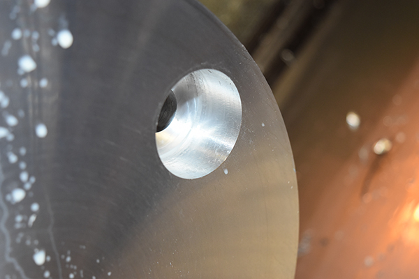
The part was flipped, due to me cutting the groove it meant I was only holding on about 1mm. I drilled one of the holes all the way through the part so that I could align it for the second operation, the reason for not doing all of them was clearance with the jaws and the fact that my drill really was not long enough.
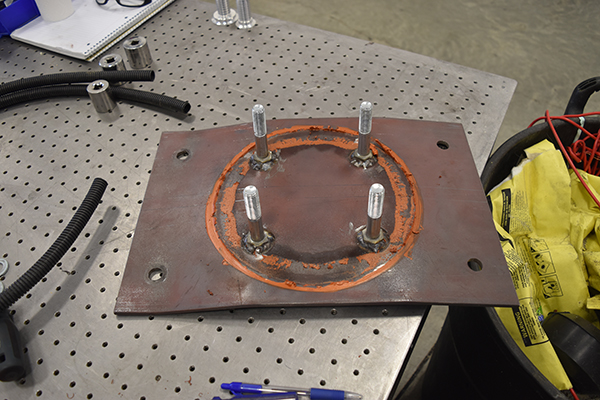
I repeated the pocket milling program to allow for some room for welding studs to the bottom plate, I would in fact be using bolts so I needed room around the head for a weld.
I drilled the locating holes in the plate for the top platen, the bolts were welded to it and the piston sealed and bolted in place.

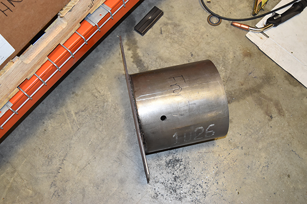
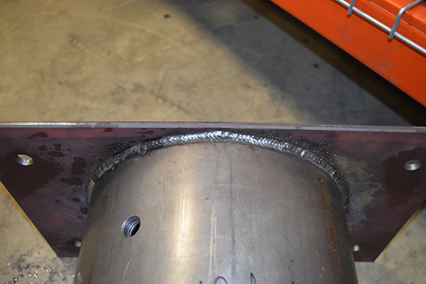
I used some hydraulic cylinder tube since I would not have to machine it due to the bore being a perfect finish. The tube was welded to the bottom plate and a hole drilled for the vacuum supply.
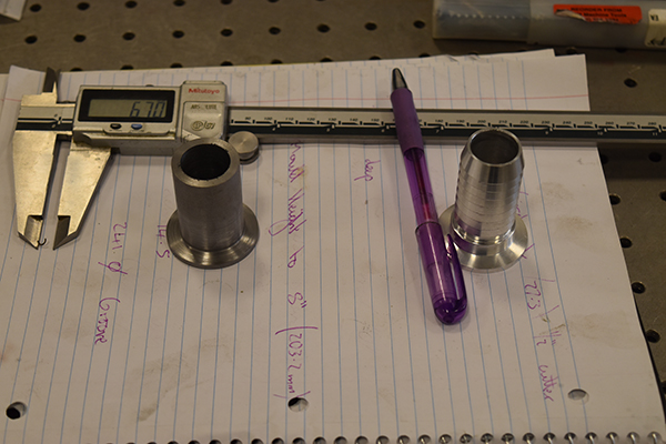
I used a manual lathe to turn a flange for the vacuum, it was then welded to the tube. I used vacuum flanged through the whole of the process just incase I needed future modification, for example the vacuum hose might not handle the temperature so would have to be replaced with a stainless one, it would require vacuum flanges.
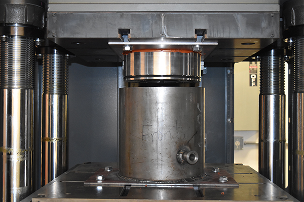
It did work at first but the bottom platen did not align properly, which is real bad, that combined with leaving the vacuum on caused the piston to catch the tube and destroy the top plate, this is 1/4 inch thick ! The welds held perfect which made me feel a little better.
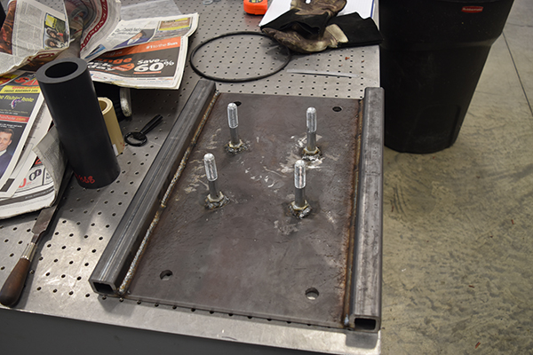
I chose to go with 3/8" plate this time and weld some support tubes down the sides, these tubes had 1/4" walls. I placed the piston back in the lathe since I had damaged it slightly. I cut the outside down to 252mm to give me 1mm of clearance either side and also machined down the back of the piston just to be sure it would never catch again.
I assembled it all together and it all aligned. My only fear is the repeatability of the bottom platen, this really should not be a concern as the press is designed for moulds with locating pins, I have found however that it's not all that accurate.
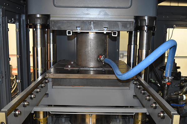
So did it work? Yes. Never before had we two good products in a row, they were now all perfect. I still did have a few issues with the bottom platen locating in the same place which did cause a few vacuum sealing issues, this was detrimental to the product being a success. It may be that I have to machine a seal with a lot more interference to combat this issue.
So in the end I managed to fix our issues and with this current modification it meant that I would not have to modify any more moulds. This modification limits the machine to a single cavity mould and makes the process awkward. The decision has finally been made to return the machine and get one with the vacuum built in, finally.
Hello, if you have enjoyed reading this project, have taken an interest in another or want me to progress one further then please consider donating or even sponsoring a small amount every month, for more information on why you may like to help me out then follow the sponsor link to the left. Otherwise you can donate any amount with the link below, thank you!