Machining a Mould
At the time of writing this (2019), I am a mould maker. I am able to show how I make these moulds but unfortunately I am unable to show any drawings on both the finished part and the mould itself. I also cannot show any dimensions, but I will say that all dimensions are machined to within a ± 0.001" tolerance. I will also add that I will not be showing the finished product either. I use this site as a portfolio to my resume / CV, it shows what I can do. I will also try to explain my reasoning of how something is to be machined.
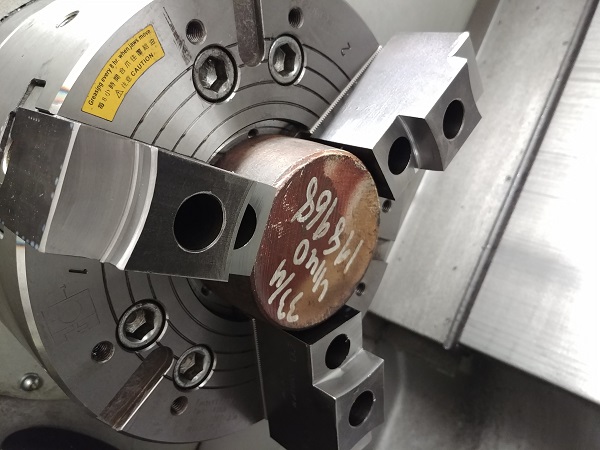
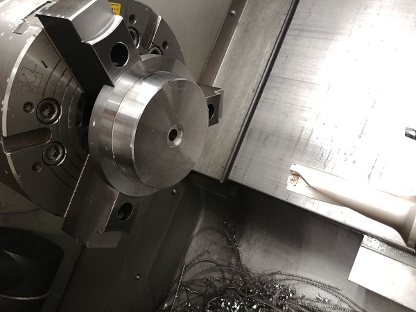
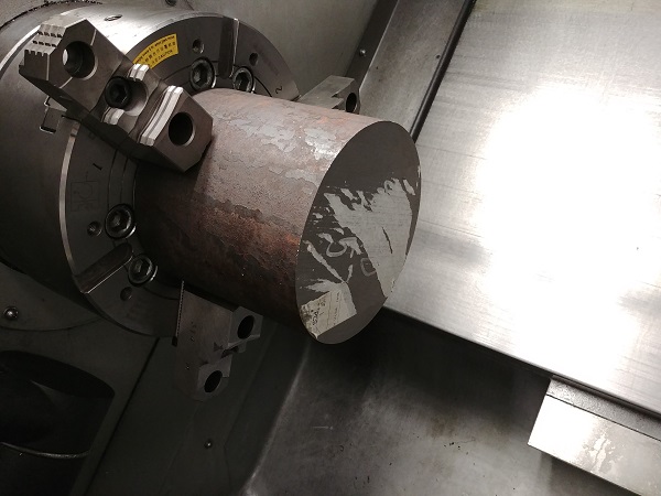
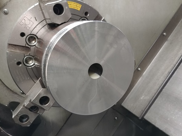
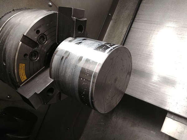
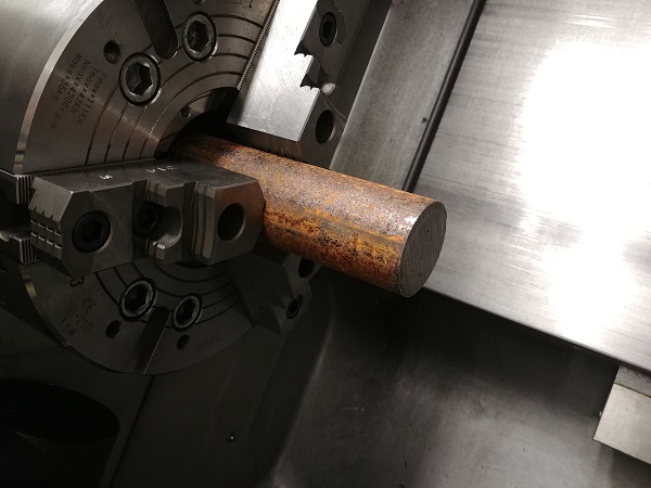
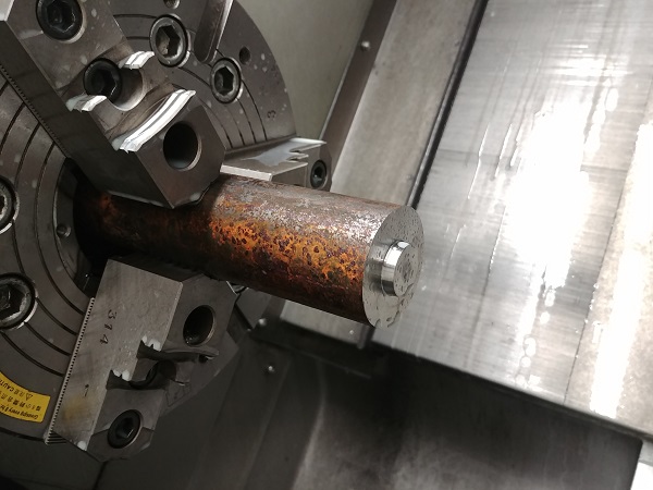
I first started with a pre-cut puck of steel. The tool probe on this machine is quite accurate, I set all tools to this when I can. If I cannot use the probe then I will set all tools to the face of the work piece as this is Z0. I write all of my programs so that I have a way to measure it before the final pass, there are always two finishing passes at the same feeds and depths of cut.
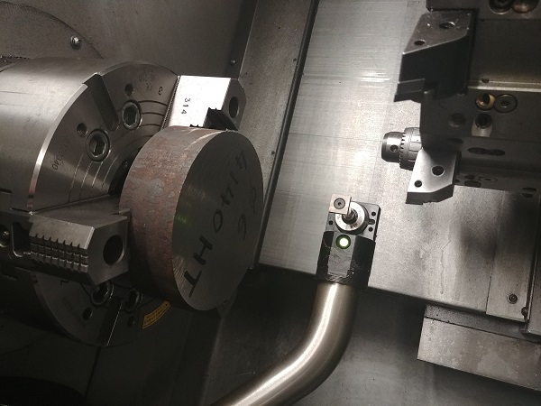
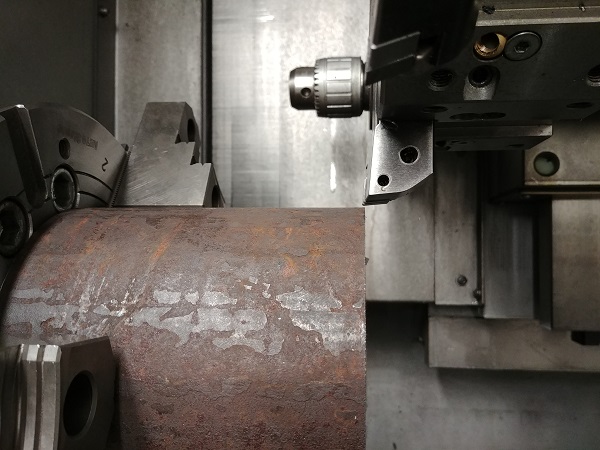
One faced I run the machine in MDI mode so that I can set tools, in this case a U-drill. With this tool I'll set the Z offset with the tool probe but the X offset will have to be set manually just because the insert does not sit at centre.
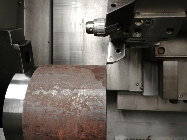
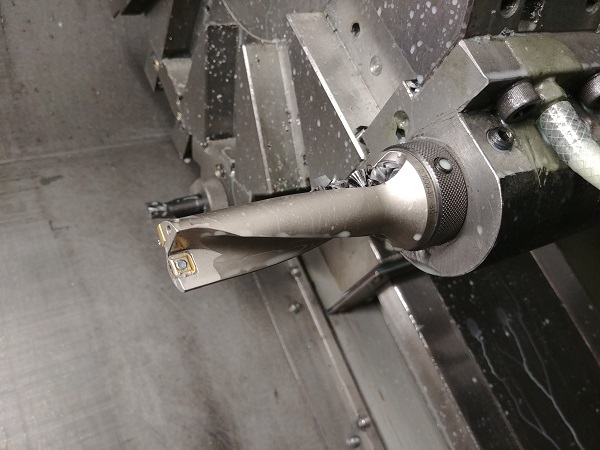
I set the chuck spinning in MDI at a reasonable speed. The art to setting a U-drill manually is not cutting the hole oversize. The way to do this is to start cutting undersize and watching the bottom of the drill as it approaches the face. The bottom of the tool wants to just barely clear, the tool is pulled out, the bore measured and input into the machine. I use U-drills as much as I can since they make holes so easily, and because they are through-coolant I don't have to worry so much about a failure.
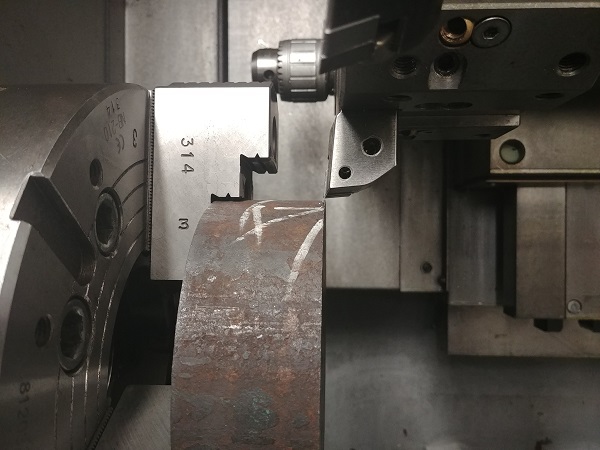
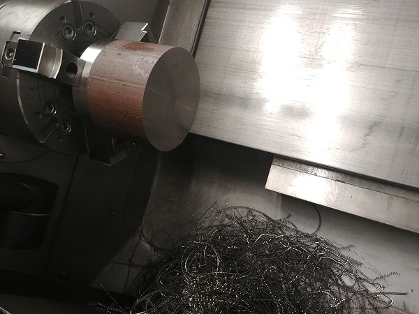
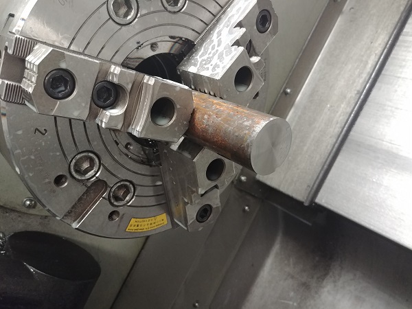
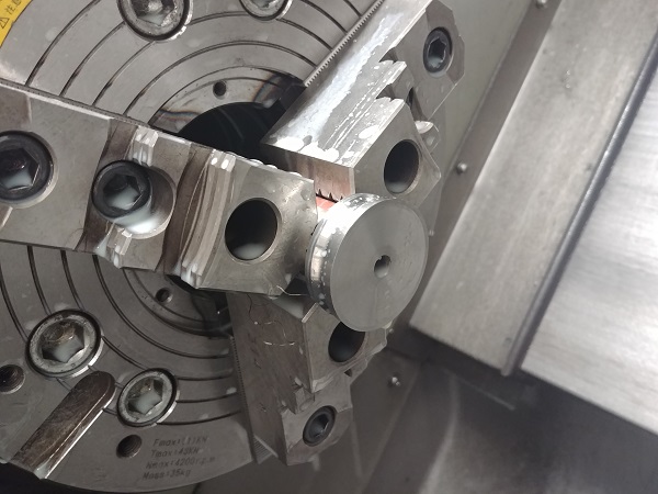
The clear difference is that this drill costs about 30 times as much as a standard drill. However a pair of inserts cost around twice that of a drill but last considerable longer, sometimes as much as 100x. Since this part had to be placed on the inside step of the hard jaws it meant that I would not have enough room to do the second op. Soft jaws are the choice when the hard jaws fail.
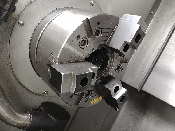
These jaws had been previously used for another job very similar to this, they required a tiny bit of adjustment.
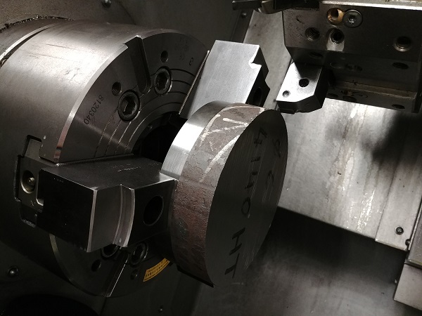
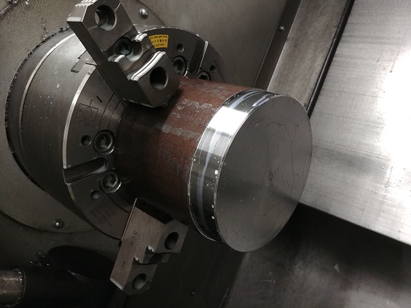
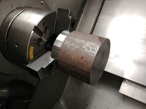
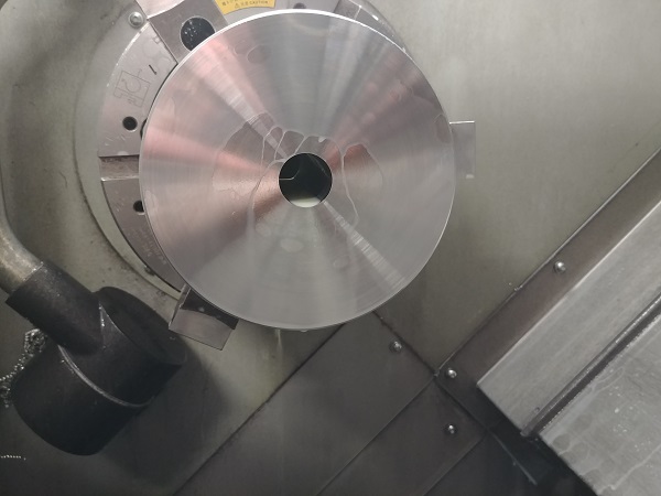
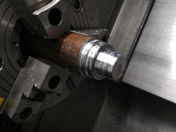
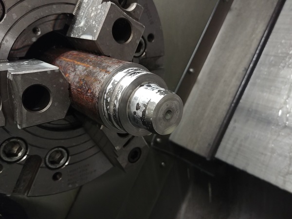
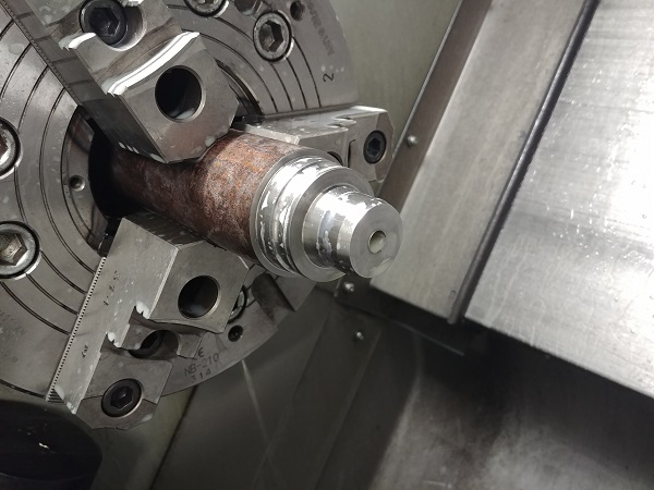
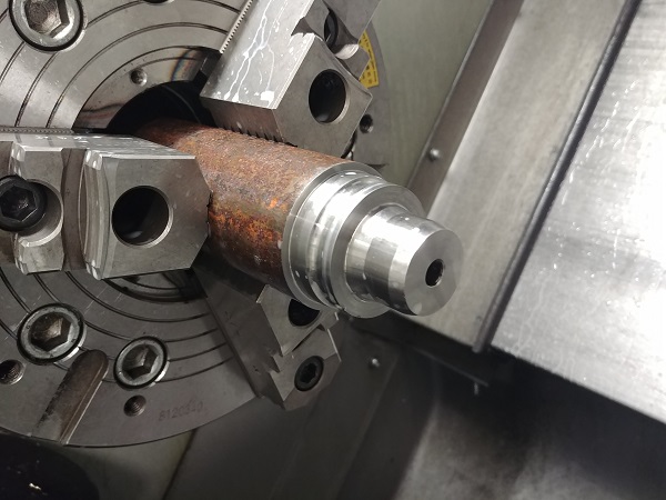
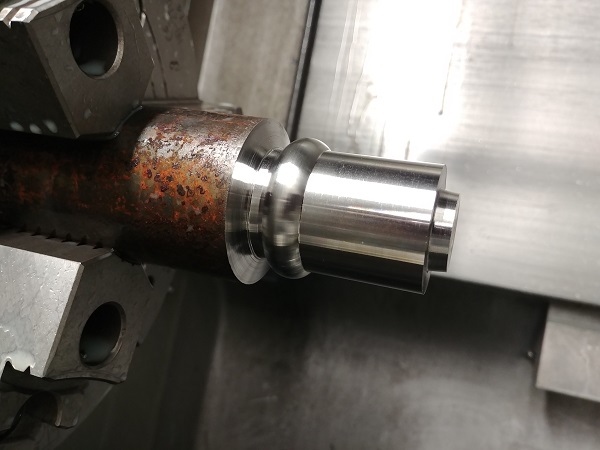
The part faced to the correct height and the outside machined to size. The outside is tapered meaning it is impossible to measure without removing it and placing on a CMM. I could measure the angle with a dial indicator but that does not give me an outer diameter. Since these soft jaws are machined perfect there would be no problem in removing this piece and locating it in the same place. The second option is to program a straight finish pass to measure, then a couple more passes to finish off the taper. Luckily this machine is very consistent and I can trust the outside dimension from the first op. The key is to keep inserts fresh and check the insert does not chip or burnish throughout the machining process.
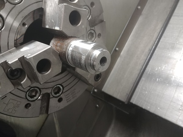
The bore piloted out with a U-drill.
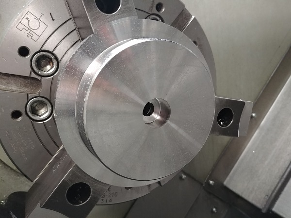
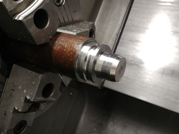
The crucial dimensions on this part are the tapers, again these can only be measured out of the machine on a CMM. I rely on measuring the straight bore since this is the only accurate dimension I can obtain. The rest depends on that I have programmed the part correctly.
The main cavity is to be machined next. I am often rushed to get these moulds complete, the closer I am to completion the more I'm rushed. I like to start off with the expensive pieces of steel for this reason. Mistakes are an inevitability and will likely happen when under pressure, If I am to make a mistake then I would rather it be a smaller inexpensive part.
The outside of these moulds are not important at all so it doesn't matter if it is machined in two operations. I turn the outside enough so that I can hold on with the soft jaws, for when I do the second operation. The U-drill was already set so I drilled out half of the inside.
The soft jaws were bolted to the chuck and the part flipped.
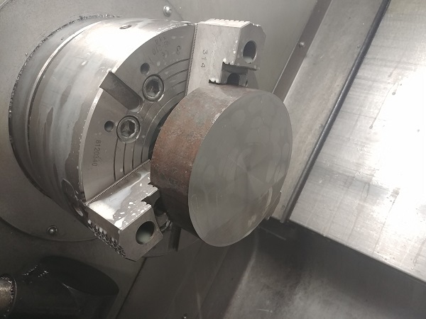
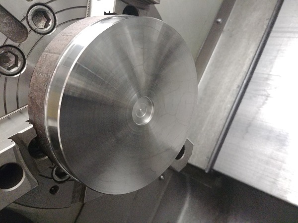
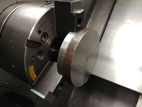
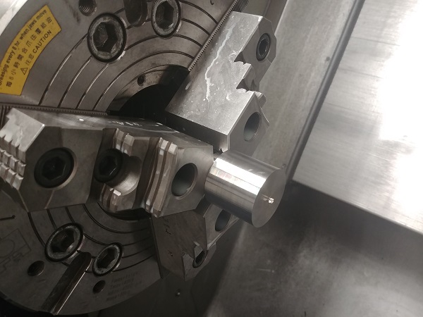
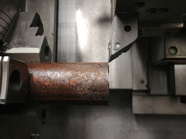
The work shift set and the first finish pass complete. I always order these billets oversize to allow for cutting tolerances. This first finish pass is to measure how much I need to remove for the final pass.

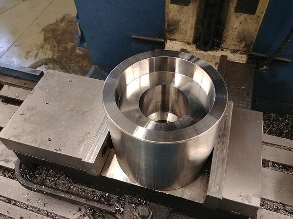
The part machined to the final height and the outside turned.
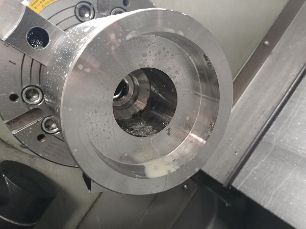
The inside drilled out, now the boring bar can pass through the full length.
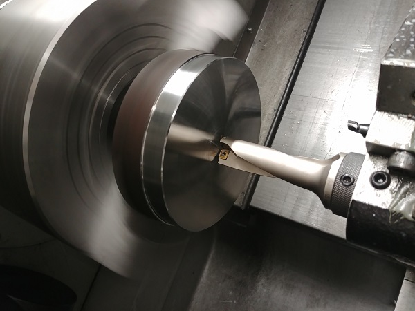
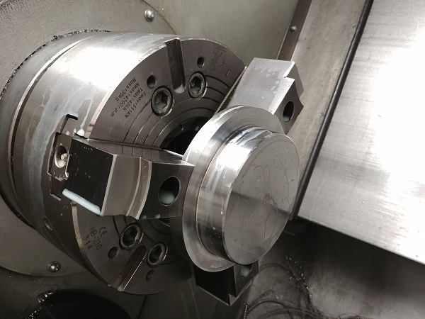
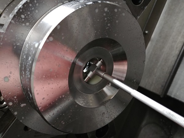
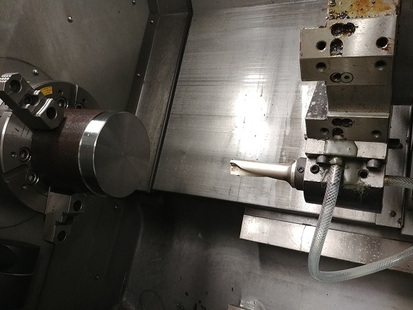
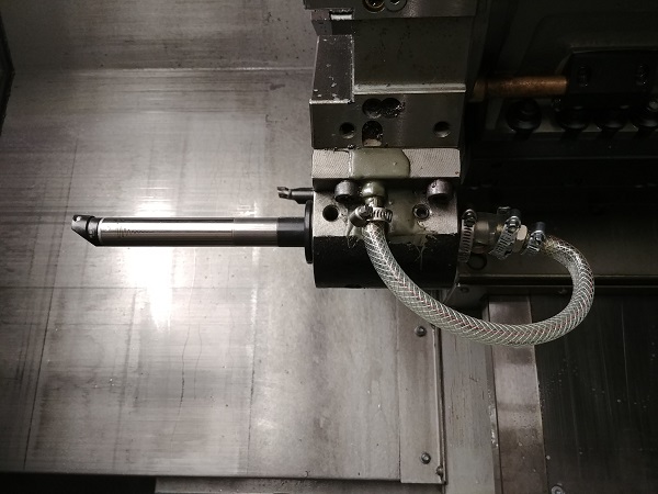
The part was removed from the jaws to set the boring bar. Since I had machined the soft jaws there was no doubt that the work piece would locate in the same place and remain concentric. It is so much easier to set the centre height and the X offset using the tool setting probe.
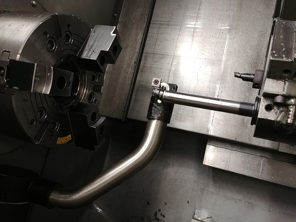
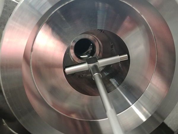
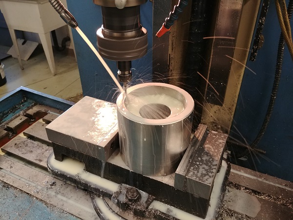
I set the Z offset of the bar to the front of the work piece. Since this cavity is for a moulded product it means that the finish must be the best it possibly can be. To achieve a good finish I have to use an anti-vibration bar, mainly due to the small bore and length.
The first finishing pass was made, slightly undersize so that I could measure it and ensure the final pass would be perfect.
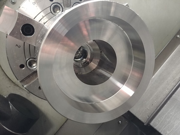
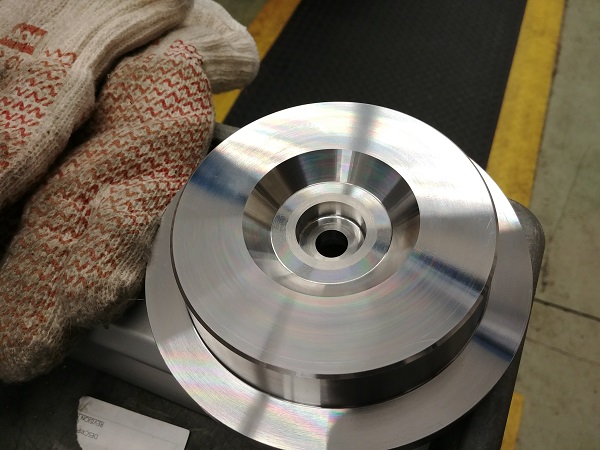
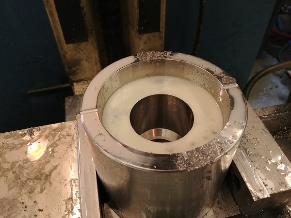
The cavity complete, I put it in the mill, some vents will be machined later on. Meanwhile I set the geometry of a turning tool, I will be machining one of the moulds inside components next.
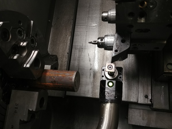
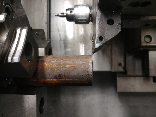
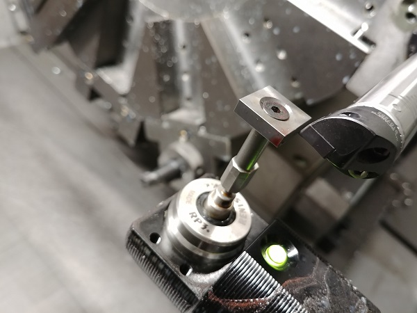
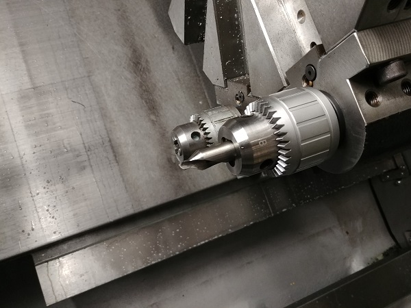
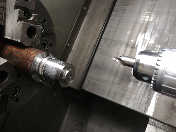
To set a centre drill I use the top and bottom of the probe, the dimensions I get in the tool geometry are averaged to get the middle.
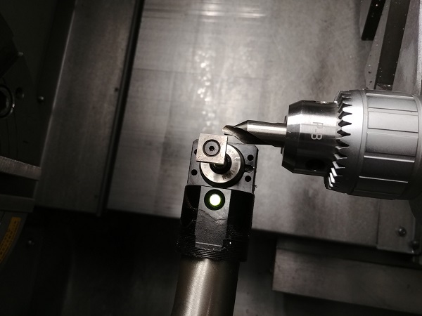
The same method is used on any type of drill. If I did not have the use of a probe then I would do it in MDI mode. Setting a drill in manual mode is a bit of an estimate. I first get the drill looking centered by eye, and as long as the drill is stationary and the work piece is spinning the drill will try to self-centre. A small dish is made in the work piece, as the drill is retracted it will move either up or down if not centered. I repeatability peck at the face until I see the drill stop deflecting, then I know I have found centre point. This method only works with HSS drills since they are flexible, a carbide drill would simply break.
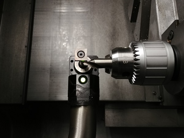
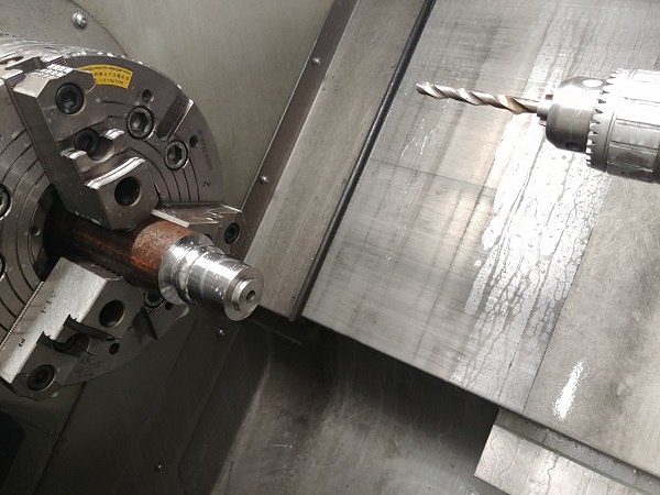
There are more options to centre a drill. Firstly a drill chuck does not always hold a drill centered or even straight. A drill chuck should only ever be used for HSS and must be set every time a different drill is inserted. The best option is to use a collet chuck as these pretty much guarantee repeatability. A test shaft should be placed in the collet, clocked central to the chuck and then the X geometry recorded. If this position in the turret is used for drills only then the geometry never needs to be reset. It is a wise idea to find the centre points of all the positions on the turret and keep them recorded in a lookup table.
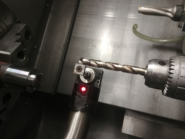
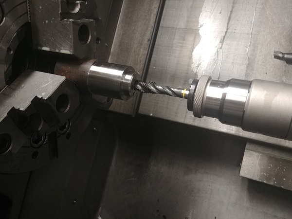
The drill was a pilot for a thread. Since this is a very basic lathe, it is a must to go with a floating tapping chuck. Anything to be tapped in a machine it is best to go with a spiral flute tap as it does not require any retraction to break the swarf, it simply spirals out of the end.
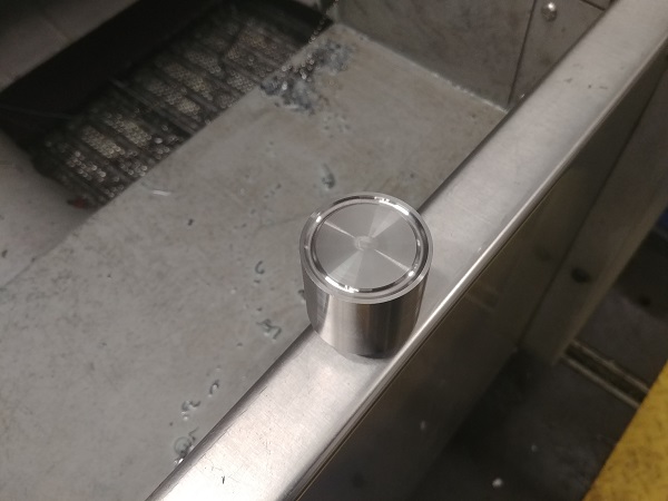
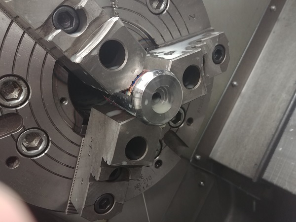
The piece is parted off and placed back in the chuck to do the second op. The face requires a channel, I use a diamond shaped insert to give the best clearance.
I use the same method of touching the top and bottom of the probe to get the insert centre.
The part complete.
This part has very similar operations, the difference is no thread, just a hole all the way through.
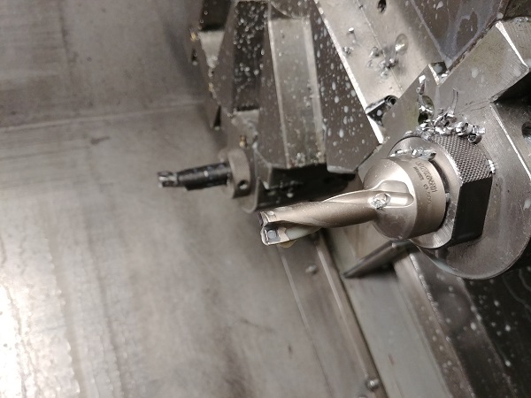
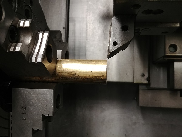
The third and final part requires a lot of clearance for it's profile. This is a DNMG insert, it has 35 degree's of clearance, this will not be enough.
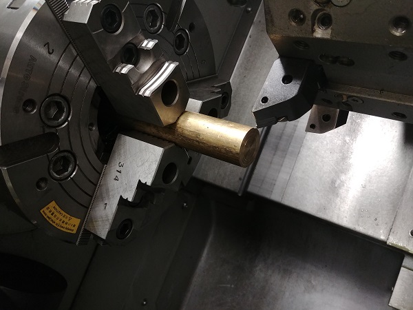
The second tool is a VNMG which has 50 degrees of clearance, again this is not enough. The final resort is to use a VNMG profiling tool, the same tool I used for the face contour earlier. This tool has just over 70 degrees of clearance, even this tool comes close but it will do the profile. The only issue with using a profiling insert is that it requires more clearance from the chuck, it also requires more material to be machined.
This tool can only be set reliably with the probe, the front and back are measured to give an average.
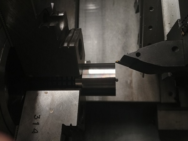
The first step is faced on with the DNMG tool, the contour is then turned with the above tool.
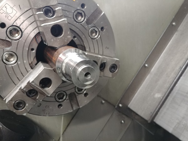
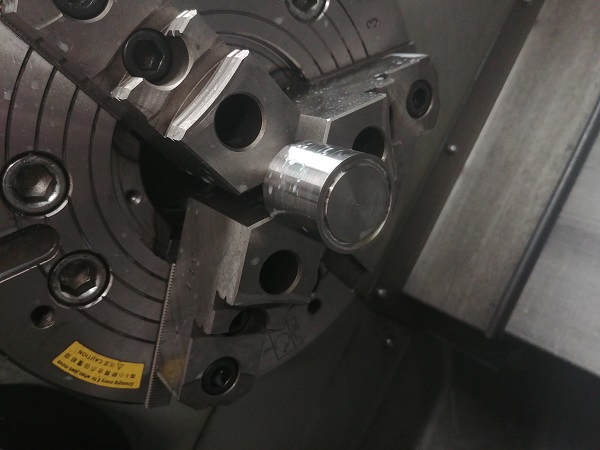
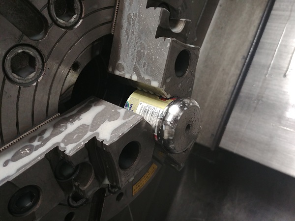
The second inner part has a second operation, I first start by holding it in the chuck with soda can packing to protect the finish. I turn the clamping pressure all the way down so I can make adjustments to get it running true, I then turn it back up.
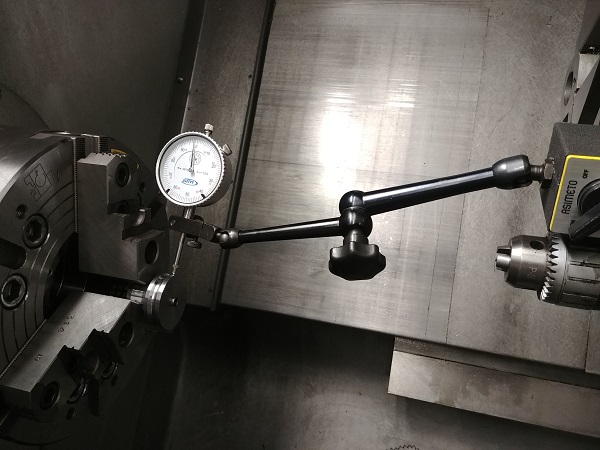
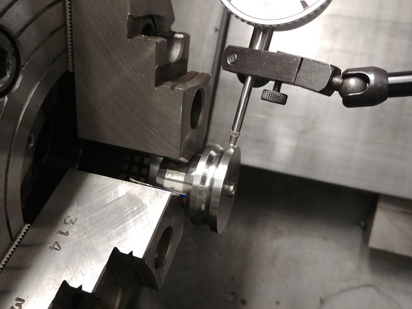
The issue with chucks is that they all have some amount of runout, so while I may have the outside of this part perfectly true at this one particular point, I may have skewed it slightly. The more important dimension of this part is the height, so that is what I clocked in the end, the face.
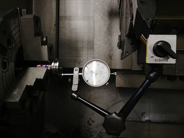
The same is done with the third inside part.
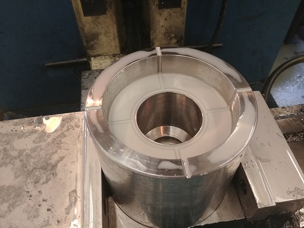
I clocked the main cavity central in the milling machine.
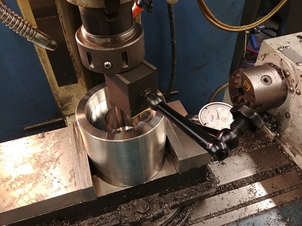
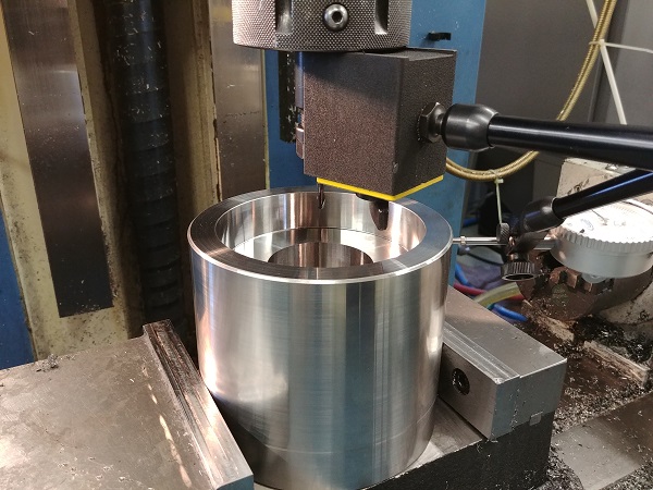
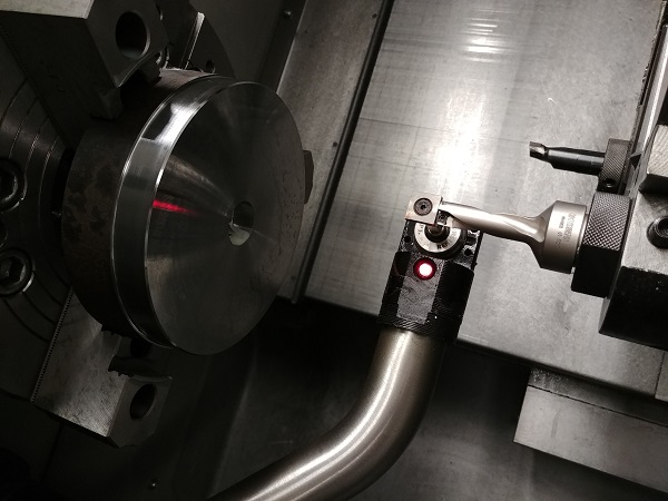
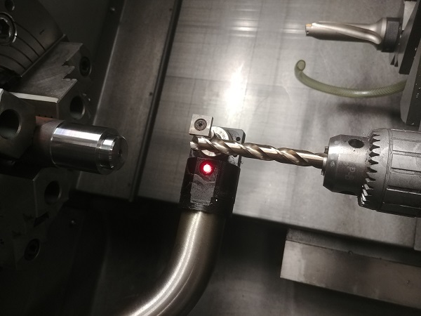
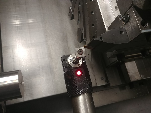
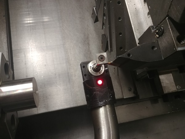
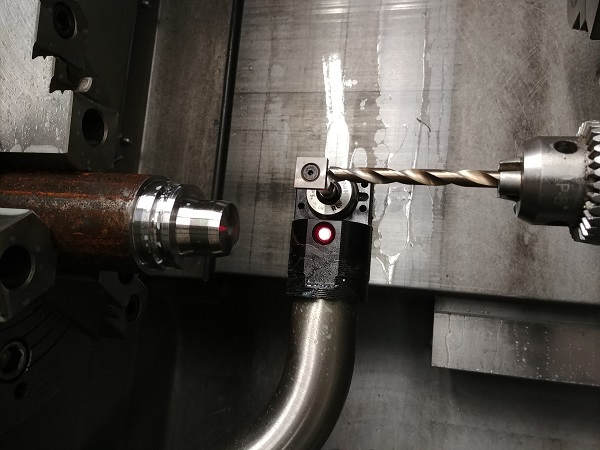
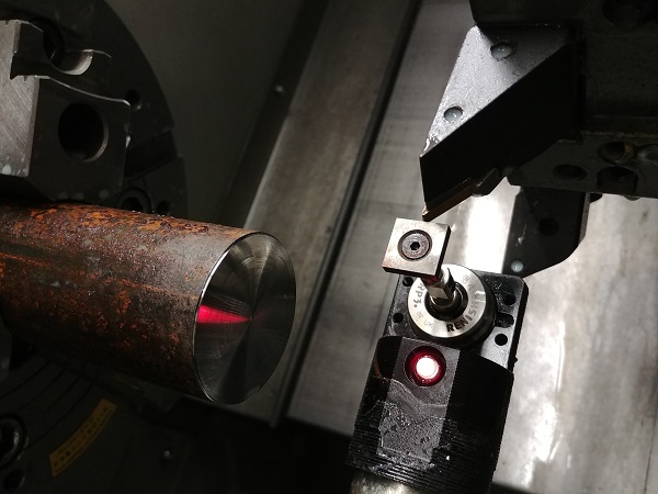
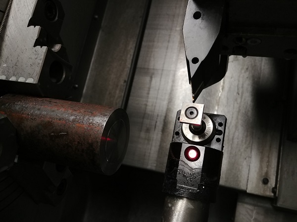
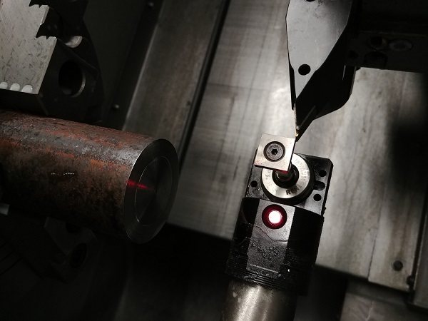
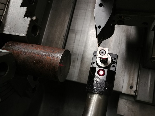
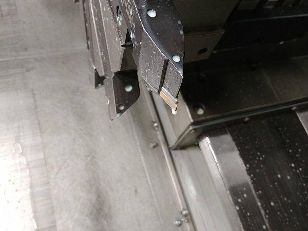
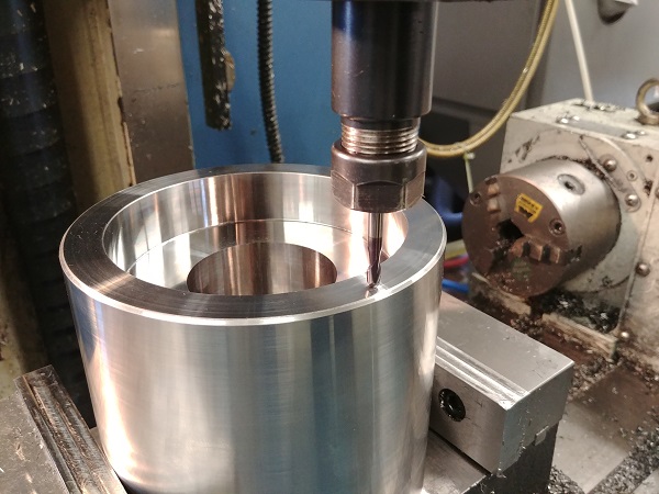
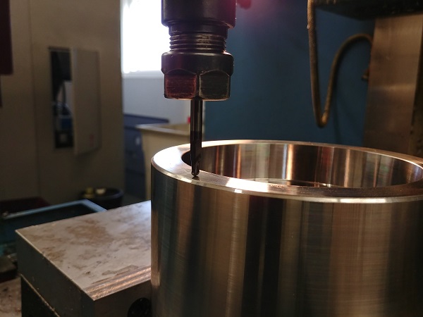
This operation is to place some exit vents around the top part of the cavity, I set the tool height watching the light beneath it.
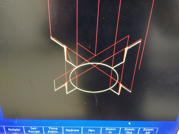
I programmed the milling path manually and ran a simulation, it looked good.
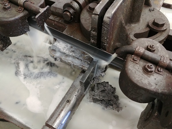
While I left the mill running I started the last part on the lathe.
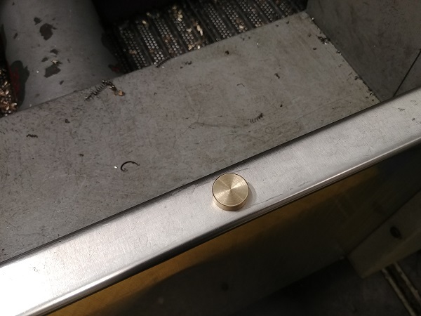
This is just a brass coin.
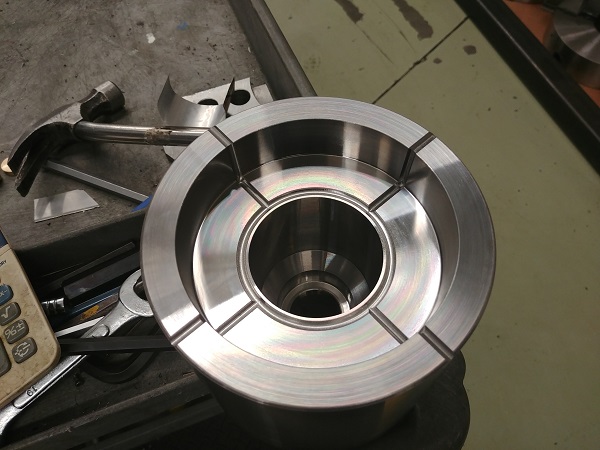
The vents came out looking really good.
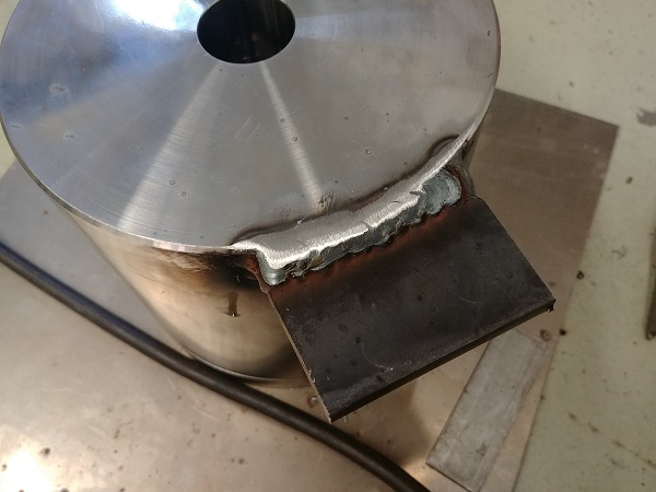
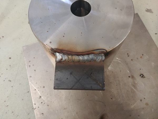
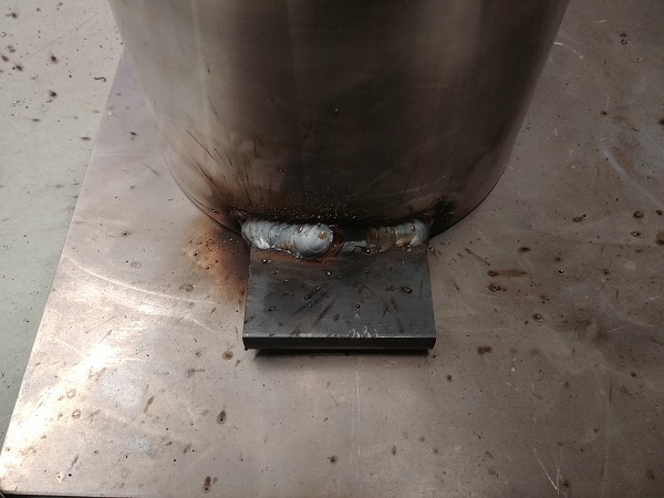
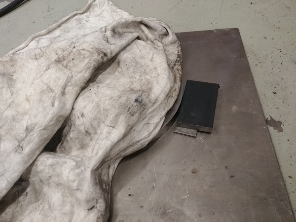
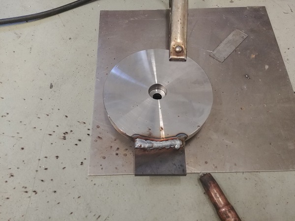
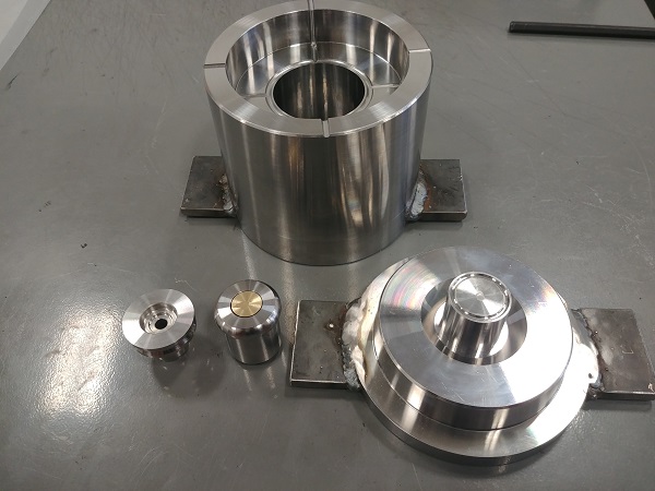
I used to mill slots into the main mould to give something to bolt it down to in the press. I decided that this was a lot more work than necessary and went with welded tabs.
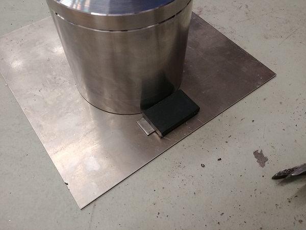
Welding 4140 to mild steel is pretty straightforward, without pre-heating, the weld penetration is pretty shallow. These welds don't have to be all that strong, they probably only see a few hundred pounds of force between them.
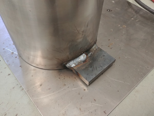
The mould and the components came out great.
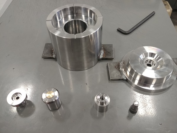
These smaller moulds are sometimes a little trickier to make just because the sturdiness of the internal tooling is less. All of these parts are programmed manually on both the lathe and the mill. I find that CAM software can often add unnecessary time to the process, it also dramatically increases the amount of memory required and risk of error.
Hello, if you have enjoyed reading this project, have taken an interest in another or want me to progress one further then please consider donating or even sponsoring a small amount every month, for more information on why you may like to help me out then follow the sponsor link to the left. Otherwise you can donate any amount with the link below, thank you!