Narrow-band AFR Meter
The first step in the road to tuning a car is knowing the air / fuel ratio to get the best economy and power when it is required. Most cars and motorcycles will come equipped with an oxygen / lambda sensor to keep the vehicle in tune, that is only if they are injection which the majority are. A carbureted vehicle can also be adapted to take a sensor to better improve tuning capabilities. The sensor I will be discussing is the narrow-band type, the other is the wide-band which is not commonly found on vehicles, perhaps only a select few of the newest models.
The narrowband has the following construction.
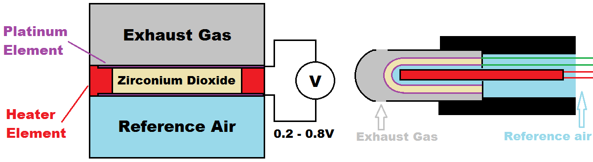
Inside of the sensor is a thimble made from zirconium dioxide, a type of high temperature porous ceramic that allows oxygen molecules to flow through it. The thimble is plated in a platinum film that acts as an electrode, this setup works as an electron pump. The reference air flows through the top of the sensor, through the platinum picking up an electron, it passes through the zirconia membrane, through the platinum electrode leaving an electron behind. As more oxygen is pumped through the sensor more voltage is produced, the sensor tries to reach equilibrium and pulls more oxygen through to reach that.
Our exhaust gas will have a ratio of air / fuel. When the mixture is rich, an abundance of fuel it will pull a lot of oxygen through resulting in a high voltage. When there is a lack of fuel, a lean mixture, there is an abundance of oxygen and therefore the sensor has to pull little oxygen resulting in a low voltage. When the ratio is just right, the stoichiometric ratio of 14.7 parts air to 1 part fuel the voltage will be at a middle ground as it will still continue to pump oxygen.
Here is an example of the output voltage from a narrow-band sensor. Since I could not find accurate measurements I had to find a controller that replicated the output voltage from a wide band, even though this information is from a reputable tuner I can say the results are not all that accurate, for one the AFR of 14.7:1 should be 0.45V whereas it is 0.33V in the table, I'm not all that concerned for this application.
| AFR (parts air to one part fuel) | Output Voltage | AFR (parts air to one part fuel) | Output Voltage |
|---|---|---|---|
9 |
0.88 |
14.0 |
0.70 |
10 |
0.88 |
14.1 |
0.68 |
11 |
0.87 |
14.2 |
0.66 |
12 |
0.85 |
14.3 |
0.64 |
13 |
0.79 |
14.4 |
0.62 |
14 |
0.70 |
14.5 |
0.55 |
15 |
0.18 |
14.6 |
0.44 |
16 |
0.08 |
14.7 |
0.33 |
17 |
0.05 |
14.8 |
0.24 |
18 |
0.04 |
14.9 |
0.2 |
19 |
0.03 |
15.0 |
0.18 |
20 |
0.03 |
15.1 |
0.17 |
Or here is an example on a graph.
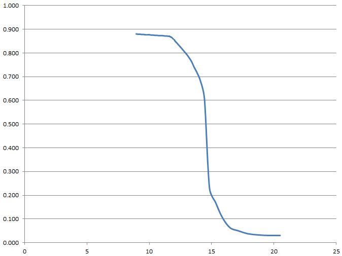
You can probably guess how the narrow-band sensor gets it's name as it can only measure between 14:1 and 15:1. The ECU doesn't even measure these specific values it instead translates as being either rich - over 0.8V and lean - under 0.2V. As a car is running it will keep swapping between the two to get an average ratio, the engine adds fuel until the ratio goes rich and then takes fuel until the ratio goes lean keeping the car anywhere around 14 to 15:1, theoretically, this happens between one and four times a second.
Now there is an optimum range for both power and economy, less fuel is better economy and more fuel is better power. As the mixture gets more lean it's combustion temperature increases which can lead to pre-detonation and over heating. Even though a lean mixture can lead to these circumstances an engine can happily run at idle on 16:1 or higher because the quantity of heat is little, this ratio at higher revs would certainly cause engine failure. To achieve the most power you need a ratio of between 12.5:1 to 13:1 which our lambda sensor cannot detect. Most ECU's will ignore the lambda over about 3000rpm and go on the engine map alone, as an engine wears the ratio can have increasing errors, not enough to damage an engine but enough to loose considerable performance. Running an engine higher than 12.5:1 will cool the combustion and lower detonation, something to consider for a turbo engine however unburnt fuel will contaminate the oil reducing lubrication and engine life, spark plugs and lambda sensors will have a greatly reduced working life.
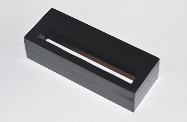
The Meter
Many expert tuners will tell you that you cannot tune a car with a narrow-band lambda sensor, in part that is true. While you can tune a car to run in the narrow-band range you cannot tune a car to increase it's performance. The point of this project is to show you what signals the ECU expects from the sensor and to lead you onto the next project which is the performance tuners alternative. Even though this sensor is not all that great for tuning it can still be used to ensure the engine only runs rich on acceleration and lean on zero throttle, since these sensors are so cheap and easy to control they are a great option for low cost carburettor tuning.
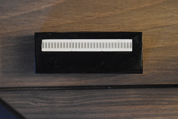
The first thing is to make a meter comprising of three segments, one rich, stoichiometric and lean.
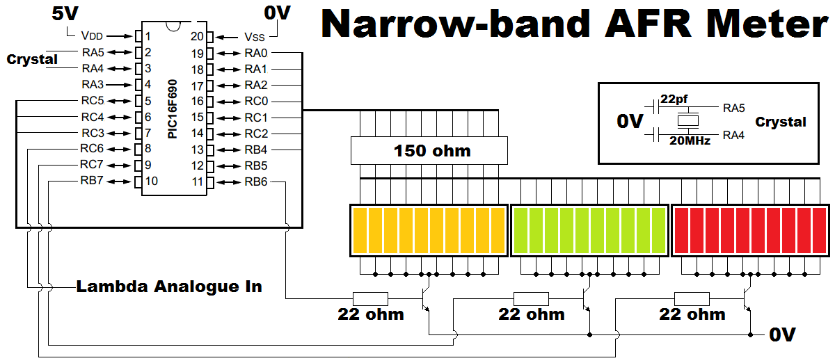
Circuit Diagram
There is one additional feature I have added in the final PCB layout and that is a 5V voltage regulator, since this is an automotive application the 12V will be far too high for the microcontroller. Note that I have placed buses in my circuit diagram to make it tidy, I have not labeled pins as if you copy my PCB design and program then it will work perfectly.
Here is the PCB layout, a copy of the file here - PCB
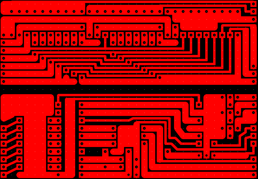
You may notice some differences with this board as I originally designed it with a serial output pin, the above design also requires less jumpers.
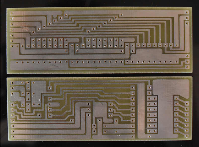
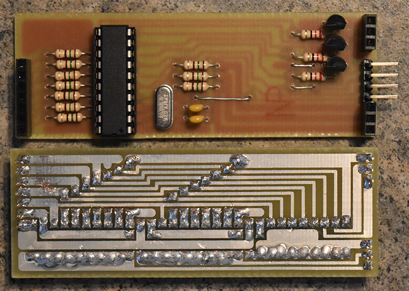
Note the extra serial transmit pin. I originally was going to use this for my car but decided it wasn't really going to be that helpful for tuning, I chose to remove the pin and reroute some traces to clean up the board. I have also included holes for a 5V voltage regulator (LM7805) and holes for a smoothing capacitor, 16V at 1uf will be suitable. The transistors are in fact MOSFET's, 2N7000's. I chose to split the board with headers however if you are confident with your program then they and the chip socket are unnecessary.
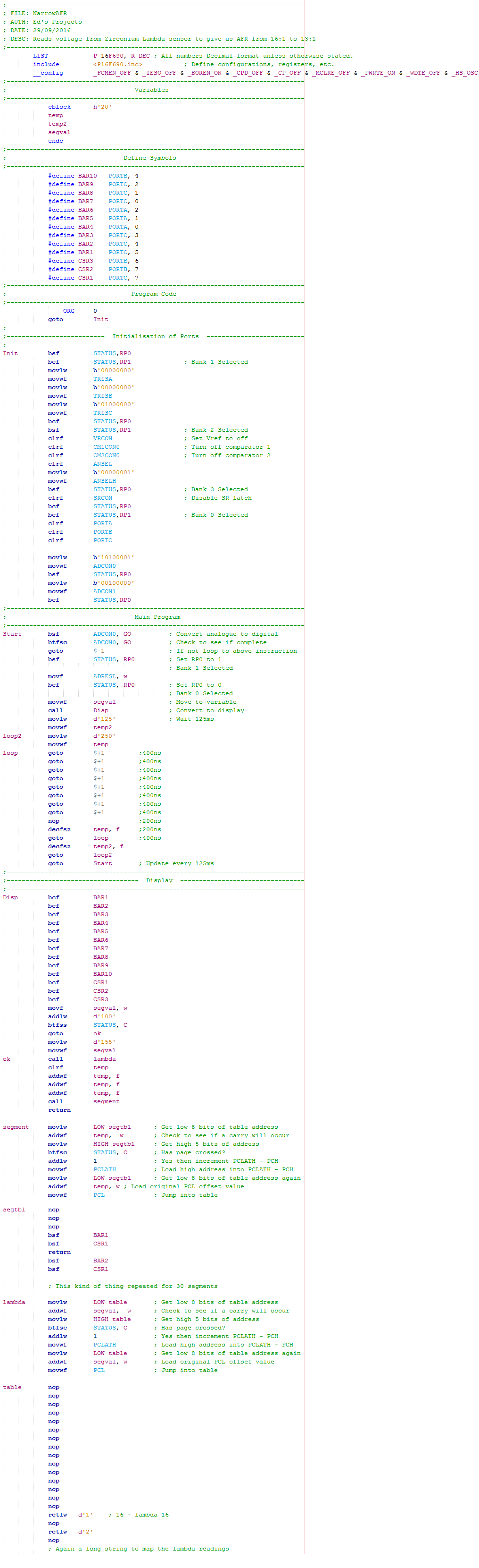
Program
The program is fairly simple, it first reads the analogue value from the lambda sensor and translates this voltage to a corresponding segment via the use of a lookup table. A second lookup table then translates this segment value to the required output pins. A delay of 125ms is then implemented to stop the display flickering too much.
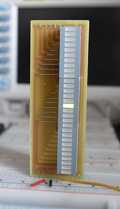
Test
The first test was on the breadboard using a potentiometer as a substitute for the lambda sensor, checking the voltage compared to the display the meter was correct. Below is an example of an AFR of 14.6:1, it is of course a lot brighter to the naked eye. The meter would also be placed on it's side, I would also recommend placing it in a box as I do later on.
3D Printing
At the time of writing this I'm pretty new to 3D printing and this is literally the first project. Ok so a quick summary of 3D printing, it uses an XYZ axis machine that has an extruder nozzle to extrude plastics such as PLS and ABS onto a platform. The 3D printer will plot many layers of plastic to achieve the 3D result. The main thing to understand is that we are printing in layers and on top of layers, that means something like the top of a box cannot be achieved without some kind of a support structure. The majority of my prints will be in ABS so to print a box I would make the lid separately and bond it using acetone (acetone melts and bonds ABS).
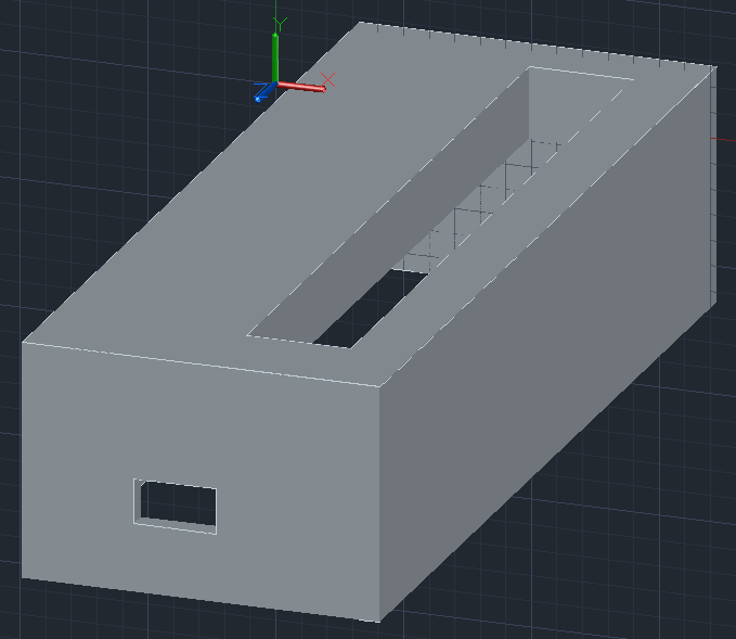
The first part of the process is a design using a 3D CAD software such as AutoCAD. The design is just a simple plastic box to house the circuit board and two holes for the display and the power input, the back will be made separately and bonded to this box. The only part I have a slight bit of doubt in is the power connector hole as it could sag. This is actually my first print so I'm not entirely sure what kind of tolerances I can achieve.
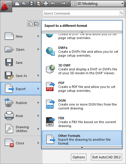
The next step is to export the design as an STL file, this can be done via the following.
A file name has to be chosen and then be sure to select "Lithography STL." as the type of file.
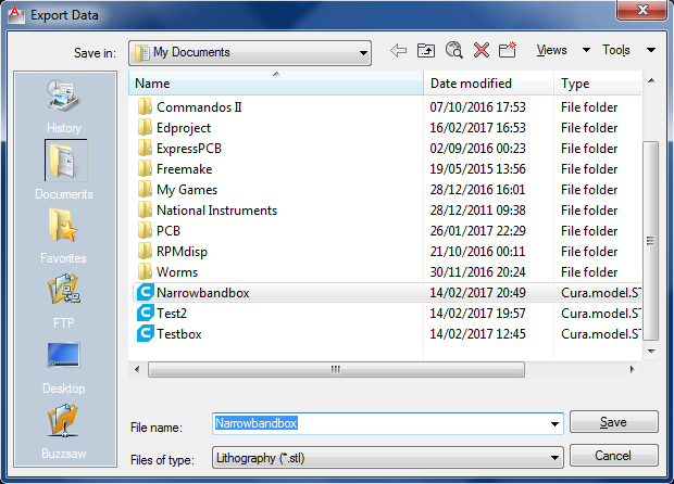
The last step is to select the object and press "enter" which exports the selected object as the file we specified.
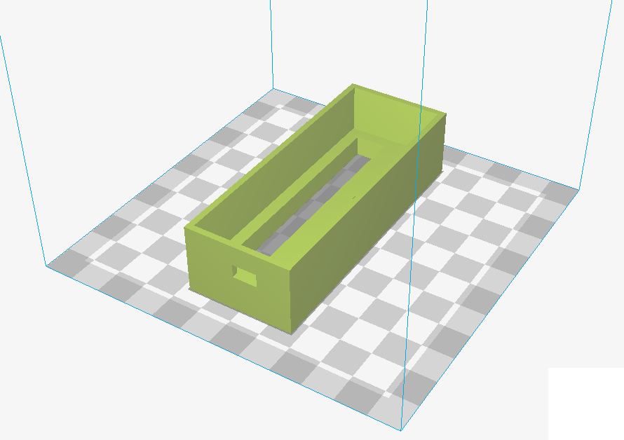
The next step is to use a software to convert the object into some G-code for the 3D printer to read. I'm not going to explain all of the settings in the software as I'm new to this and I don't want to give any false information, some of the settings do apply to the printer your using and the type of filament (type of plastic your printing with). The software to download is Cura which at the time of writing this is supposed to be the best out there and it's free. Here is what the design will look like on the print bed. I will likely do a whole project on 3D printing at some point (check projects as I may have written it).
Since I was not going to explain the software and what goes on between it and the 3D printer I was planning on taking a quick video of what is actually a 2 hour process. It took me quite a few attempts to get the printing right, I managed to fall asleep through printing and forgot to take a video, I also tried using acetone to smooth the surface but that turned into a disaster. The end result is far from perfect but functional, this will probably stay in my car for a week or two so it doesn't really matter too much.
Car Wiring
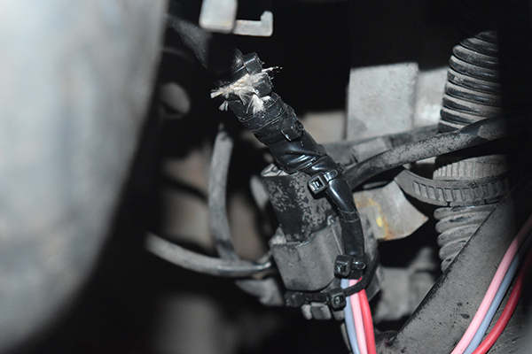
The next step was to find the correct wires, finding the lambda is the easy part as the sensor will be on the engine manifold above the catalytic converter. Connecting up the wires can be slightly more difficult depending on the type of car or it's type of lambda sensor. In general lambda sensors will have either three or four wires, two for the voltage output and one or two for the heater, if one then the other is grounded internally. For my car it has a four wire lambda, the one wire we need is the black one as this is the voltage output. The two white wires are the heating element and the grey one is ground.
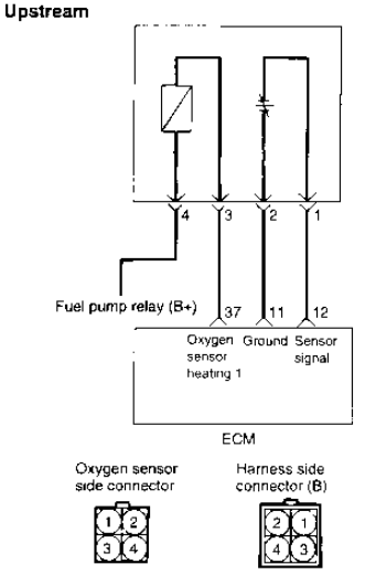
If in doubt it is always best to seek the manufacturers manual to see what wires do what, even though there are no colours there is the connector. From this diagram I get a supply, ground and the sensor signal meaning that I can splice off three of these wires.
Note that in the design I have provided there is the addition of a 5V voltage regulator but the actual unit I have built here is an earlier version and does not have one on the board. The voltage regulator was been added between the supply.
The next step is to find a way to route the wires from inside the engine bay to inside the car. Ideally you shouldn't be drilling unnecessary holes through the firewall, a common option for a single wire is to route it between the door column, a better option is to find an already existing hole in the firewall such as those for the aircon. Since my car is intended to be used worldwide it means that there are holes in both the left and right side of the car for a wiring loom, since this particular car is north-american it means that at the right side is a hole going from inside the engine bay front wing to just behind the passenger foot well. The right picture shows the wires I've spliced onto the sensor side, the wires were so short I couldn't use heat shrink and had to resort to tape, hence the cable ties. It's not ideal but not permanent so will be ok for the next month or so.
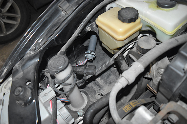
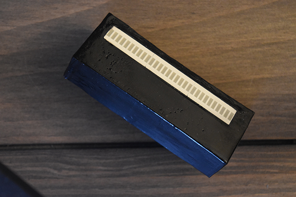
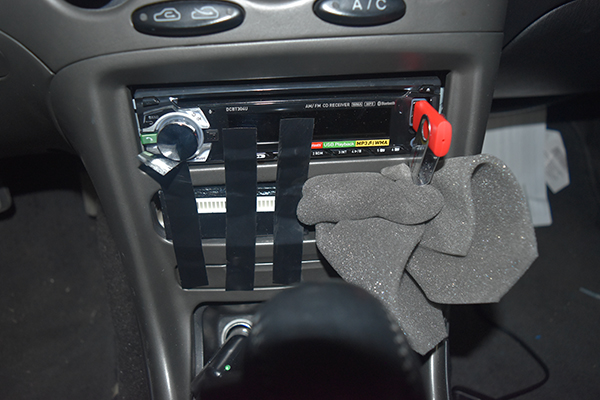
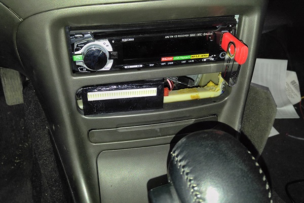
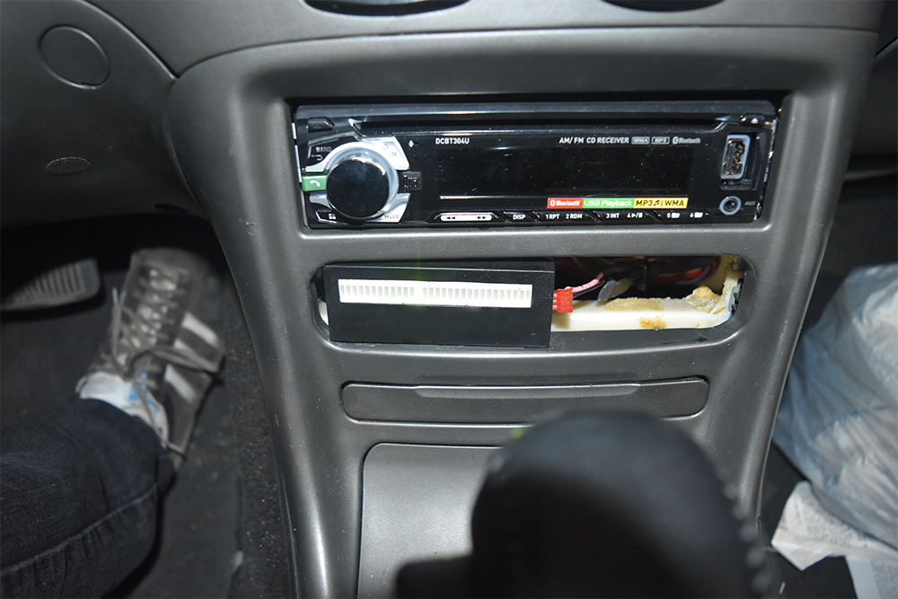
Here is where I've placed the meter, somewhere discrete as I don't want to attract attention to my car. Since the meters only going to be here for a month at the most I chose to use RTV to stick it in place, it should be easily removable. The tape and packing has been placed there to keep it in place for the RTV to set (RTV is a high temperature silicone sealant, I had it spare). The right picture of course shows the finished result, when I finally fit my ECU I will make a surround so it won't look "homemade" like this meter does.
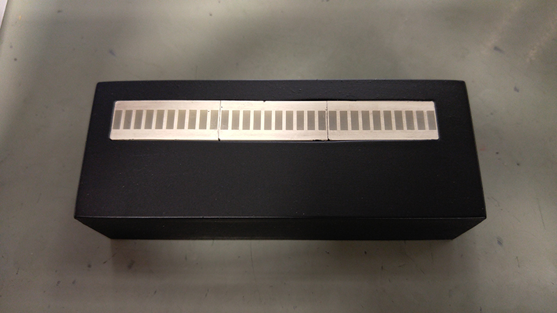
A few weeks after printing the above I got a new 3D printer and the results were almost perfect straight away.
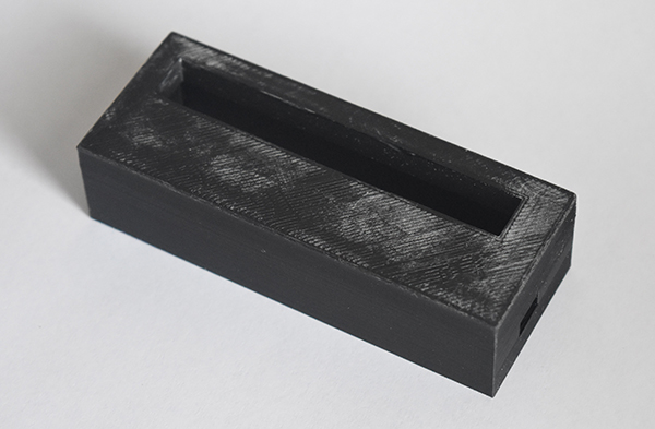
Another picture of the assembled meter.
The meter installed in the car and working.
Test video
I made a quick little test video showing the ECU trying to find the stoichiometric point and then running rich when I put my foot down.
Hello, if you have enjoyed reading this project, have taken an interest in another or want me to progress one further then please consider donating or even sponsoring a small amount every month, for more information on why you may like to help me out then follow the sponsor link to the left. Otherwise you can donate any amount with the link below, thank you!