OLED and SD Card
This is going to be quite a large project since there are many factors to consider with each of these parts. Firstly the OLED display uses LED technology instead of the older transflective technology, the difference?, the response time of the transflective is around 400ms whereas the OLED is about 1us. The OLED will use substantially more current, however due to it's really fast response time it can be used to play video whereas the transflective (LCD) is far too slow. The LCD is a monochrome display, it can only display a contrast of two colours, black / white, blue / white, etc... The OLED has many additional features such as it can work in 4-bit grayscale, each pixel has 16 different colours, or you can opt for a colour OLED which will do 32-bit colour if necessary.
Why go for the SD card? well it is by far the easiest and most convenient storage device for microcontrollers, why?, it can be interfaced using SPI. The SD card can hold tremendous amounts of memory, such as 512GB of memory, imagine how many EEPROM or FRAM chips you would need to cover this. Media is the reason for choosing SD cards as pictures, video and audio use a tremendous amount of memory where saving media on multiple chips just adds unnecessary complication.
OLED Display
Firstly I will discuss the OLED display as it differs quite substantially from the graphic LCD. Below is a comparison of the transflective graphic LCD of the left and the OLED display on the right. As you can see one does at best a silhouette whereas the other represents an image. The OLED is an example of the grayscale type which displays a total of 16 different shades of colour, yellow for this example.
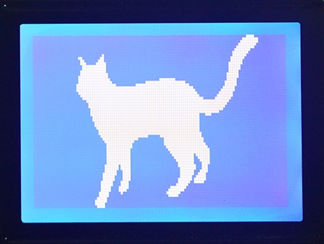

The major difference with these displays is the data that is supplied to them, you will quickly find that the OLED is more difficult to control the image than the LCD. The LCD works on a system of rows, each row is eight pixels high, each pixel represents a bit, therefore one byte will write eight pixels. The display needs to be directed which row and where to start of that row, it is very flexible due to it's pointing system allowing the user to write single characters without affect the rest of the display. Forget all of that for the OLED.
The OLED works pixel by pixel, the data in determines what colour that pixel is. Since grayscale is 4-bit it means that our 8-bit in represents two pixels. If we were dealing with a colour OLED then one byte could represent up to 256 colours, or four bytes could also represent just one pixel using the RGB table. Since I will be using grayscale we are stuck to two pixels per byte. A start line is chosen and each pixel pair are individually written, when the end of the row is reached it jumps to the next and so on. The problem with the OLED is that we can only choose the start of a line, therefore the display data is normally saved in the microcontrollers RAM, when we have made the changes we want to the RAM it is sent to the display, of course this would require 4k of RAM which we simply don't have. Note that the terminology for a temporary storage of data is known as a buffer, so we would require a 4k buffer.
Hardware
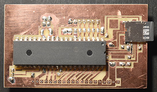
For all of this project I will be using the 16F887 microcontroller. I first placed the microcontroller on a breadboard to get the OLED working before I was to put it onto a circuit board, the board is required to place my SD slot. It didn't a lot to get the OLED working so I proceeded with placing it on a board, it didn't work. I spent a whole day trying to figure out what was wrong, I desoldered parts, checked the crystal oscillator, lots of things, turned out to be a software issue with the brown out reset, I was running the circuit at 3.3V where the brownout is at 4V.
Since I was going to use 0.8mm board I chose to design the microcontroller to stick out of the board, this could then be plugged into my programmer. I will not be choosing this method again, I should have just used a programming header, I also managed to get the pins on the SD card backwards, in the right picture you can see the jumpers due to my mistake.
This particular OLED uses the SSD1325 driver which allows me to run either two different modes of parallel or two different modes of SPI. Since the SD card will be using the SPI slot I chose parallel interfacing, I could have used both SPI however this would greatly complicate and slow down the program due to a lack of microcontroller RAM. An SD card reads 512byte blocks, now imagine we can only hold 128byte on our microcontroller, that means we would have to read the first 128 bytes of the SD, swap to OLED and send the data, then read SD again, skip the first 128 bytes and now read the second 128 bytes, back to OLED, then back to SD, etc... Using the SPI for the SD allows us to directly send data via parallel to the OLED.
Here is the pin diagram for the OLED display. As you can see it is very similar to that of the graphic. One major difference between this and the graphic is the working voltage, it must be 3.3V. There is little need to read the display so the R/W pin can be tied to 0V. The reset pin is not needed, RES pin can be pulled to 3.3V. Chip select is not required for parallel, CS is pulled to 0V.
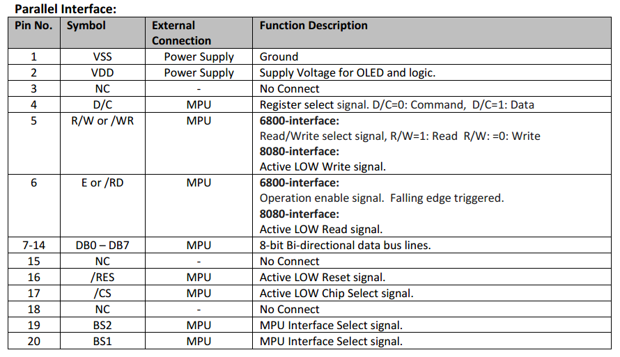
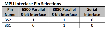
The last two pins control which interface we want to use, I will be choosing 6800 mode as this is the parallel we are used to. I would not recommend 8080 parallel as it's a little more complicated to use and for me there are no benefits over 6800 mode. 6800 mode allows us to select between read / write with the R/W pin and between data and command with the D/C pin. Data is clocked by a pulse of the enable pin, the falling edge clocks the data.
Software
This part is not all that difficult but like with most displays there is an initialisation procedure. There are two instruction tables for this particular controller, the second which I have not shown deals with pixel configuration such as the grayscale values or precharge voltage levels, stuff that's unnecessary to change.
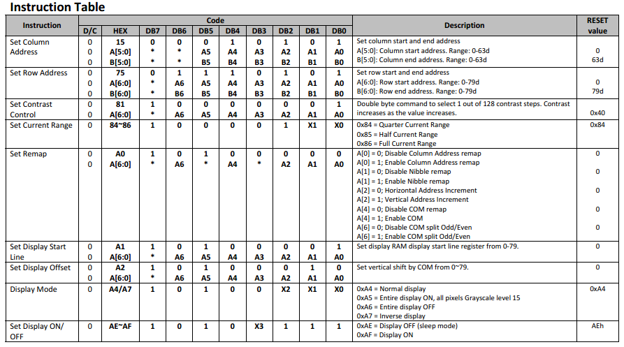
Set Column Address - The controller is designed for a 128 x 80 size display, however it is possible that we don't want this size or we only want to write to a specific section of the display, this command allows us to set the edges of our write area. Since my display is 128 pixels wide I simply write command, then zero and then 63. Note that each column consists of two pixels, hence 63.
Set Row Address - Similar to the above except we are dealing with rows, my display starts at row 13 and ends at row 76. Something to note is that earlier I said you could not write to any section of the display, you can with these two commands however this is not the standard way of doing things, a completely new image is normally sent instead.
Set Contrast Control - The standard contrast is a little dim but ok for most purposes, increasing the contrast will increase the current consumption, you may also find that increasing it too far will loose colour depth in the image.
Set Current Range - This is very much linked to the contrast and will determine how bright the pixels are, it is best to set this at the maximum otherwise the display appears too dim.
Set Remap - This is a very important setting as it controls how the pixels are to be written to the display, as you will notice the display starts writing at the bottom left corner and writes line 0, then 2, then 4 etc... I will show how this is to be configured in my program but basically by changing the com/split bit to one, this allows us to write line 0, 1, 2 etc... We then set Com bit and Column address bit which starts us writing in the top left corner like a normal display.
Set Display Start Line - The line we want to start at, after changing the remap we are really starting at line 76.
Set Display Offset - This will offset the start line, after some tweaking this turned out to be 9.
Display Mode - I find this mode to be a little pointless, all of the other options should be done with data and not the settings of the LCD. Inverting the pixels may be useful, I have however done this in my program as it will be required.
Display On - Yes
Initialisation Program
This OLED will work straight out of the box, the only command required is to switch the display on, an initialisation process is required for your application and for you to set the displays boundaries. Note in my program I have used LCD throughout, an OLED is not an LCD but it makes my program much easier to read by using the term "LCD".
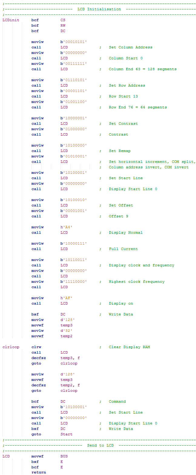
It would be wise to tie the CS and RW pin to ground on the hardware as these pins are never going to be high.
This command is in the second instruction table, increasing the clock frequency will reduce display flicker, it will however draw a lot more current.
We loop a total of 4096 times in order to clear the display RAM as when powered up it will contain random values.
Set back to line one and ready to receive data.
The enable is only required to be pulsed for 100ns, since at 20MHz instructions are 200ns there is no delay required. The clock cycle time for the display is only 300ns which means that no delays are needed throughout.
If you look through some of my projects you will come across a GPS module that required a 6kbyte lookup table to store a total of just six images. Now consider this display, it requires 4kbyte for a single picture which is the reason we need a larger storage area. I also had to write each of the 8000 bits manually before, there is no way I will ever write a 32000 bit image by hand.
A simple option is to save images on an SD card using a computer, the microcontroller will then read the card, locate the file and display the image.
Hello, if you have enjoyed reading this project, have taken an interest in another or want me to progress one further then please consider donating or even sponsoring a small amount every month, for more information on why you may like to help me out then follow the sponsor link to the left. Otherwise you can donate any amount with the link below, thank you!