Twin engine Reliant Scimitar
Firstly you may be wondering why a twin engine car and not just a larger single engine. I want a car that can be used as a moderately efficient daily commuter as well as a powerful muscle car, there are two ways of doing this. The first way would be to use a V8 engine and only run four of the cylinders, but this would require the valves to be lifted on the unused cylinders. This would require a little bit of machining, the main problem is the valve and piston clearance, which is a major issue on modern engines. The other option which I have decided on is to use two engines, the second engine can be engaged when I require more power.
Secondly why would I choose a Reliant Scimitar. The Scimitar was built on a ladder chassis and had a fibreglass shell, this means that the chassis can be easily restored, there are no worries about the body rotting, the body can be easily reshaped and the car only weighs 1200kg. The car incorporated a 3.0L V6 Ford essex engine with a four speed box, resulting in a power of about 140bhp and 0-60 in 8.9 seconds. Unfortunately the fuel consumption was about 20mpg, a modern engine with twice the power would better this. Due to the economy being so poor these cars have greatly lost their value, making them a favourite for kit car enthusiasts.
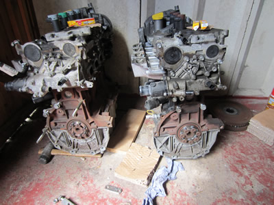
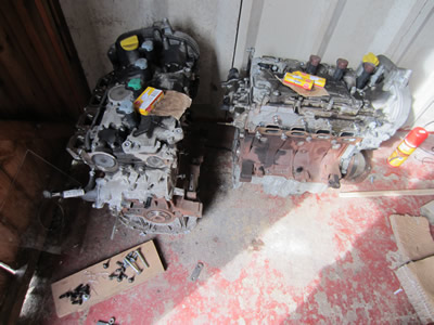 My first step was to locate two engines with similar mileage, a decent amount of power and cheap. I managed to locate two renault megane engines, 16 valve, 1.6L, 110bhp for £120 each. The engines included all of the ancillaries, so the first thing I did was remove the air-con pump, alternator, clutch, flywheel, airbox, etc...
The next step was to measure up the mounting lugs on the front of the engine, this proved to be quite difficult, but I got there in the end.
I spent quite a lot of time wondering how to connect the engines, a chain was the final option. I bought a one inch pitch chain, sprockets and some bearings including aluminium sheet to connect the engines and make a box to house the chain.
July 14/07/2013 - Age 20
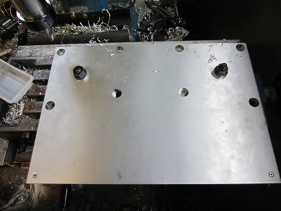
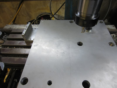
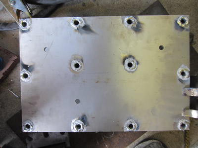
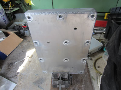
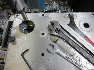
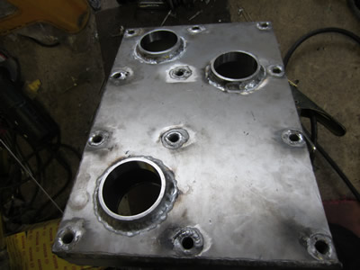
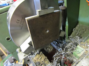
Today I started work on making the box for the chain housing, it must be structurally strong and sealed to hold oil. It was a real pain to mill holes in it due to the bed on my miller not being big enough, I had to clock the plate and mill one hole at a time, it took a considerable amount of time. A pop rivet was placed in each corner of the plates as I had to make two of the same.

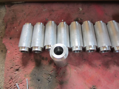
The next step was to make a set of spacers on the lathe, a total of 12. These are to provide structural support for when bolts are placed through the middle of them, these shall be welded in placed to keep the oil sealed in, this project was the reason for me to buy a TIG welder. I chose a TIG welder over MIG so that I could weld any material to a high standard. I was talking probably about £1500 upwards for a TIG setup, I managed to buy one new from an auction site for £650, then £180 for a gas bottle. At the same time I managed to make £800 profit on a car that I fixed, so this payed for the welder.
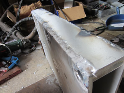
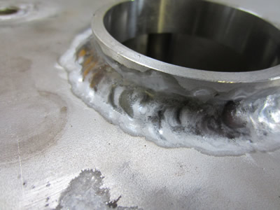
Its the first time I have ever done any TIG welding, it took quite a bit to get into, but the results are quite pleasing. I found that the best method was to crank the current up and use a circular motion with the torch, its just learning to keep a steady hand and not touch the work piece with the electrode, hence some of the black soot marks.
July 21/07/2013 - Age 20
Another week has passed and I have got quite a lot done, one more week and hopefully the engines will be running. After struggling with drilling the holes in the chain box I decided that I must get someone else to drill out the engine connecting plate. I did quite a bit of searching around trying to find a machine shop to do it for me, I originally got quoted about £100 but they then later decided it was going to be £700, way too expensive. So instead I went for laser cutting which will cost me £72, unfortunately I'm not sure when it will be done, this will be the determining factor of whether I get the engines together this week or not. Later that day I bought 10m of 1inch box section and 10m of 1inch steel tubing. I will be building a cradle for the engines so they won't be damaged when I run them, I'm also hoping that I can drop this all as one unit into the front of the car.
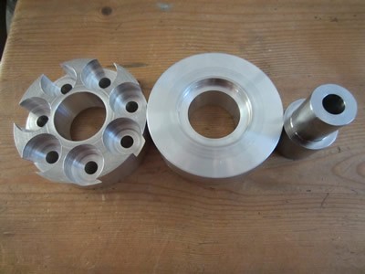
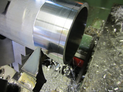
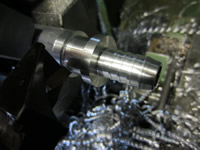
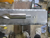
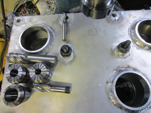
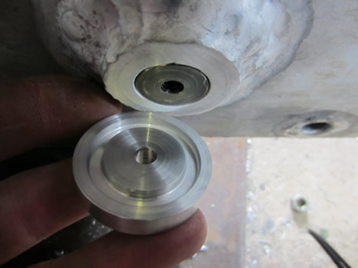
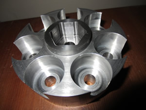
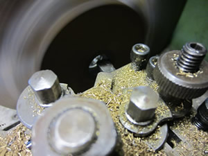
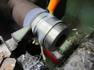
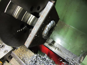
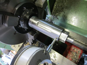
I got a bit fedup of milling the large plate so instead I did some turing on the lathe, and then some further milling. This part is for the end of the crankshaft replacing the flywheel, it is made from aluminium, a vanadium steel insert is to be pressed inside it and keyed in place.
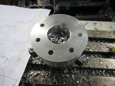
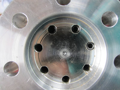
I don't have a dividing head for my miller so instead I had to make a CAD drawing to work out all of the positional drilling points.
Measuring the flywheel was quite difficult as all of the holes were different distances apart, I'm guessing this is so that its impossible to get the flywheel timing wrong.
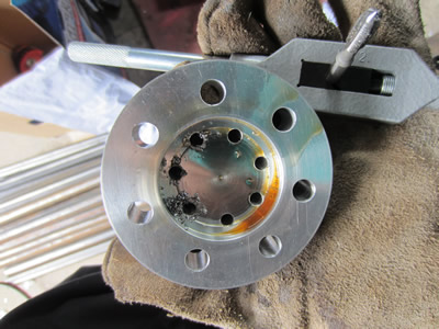
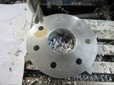
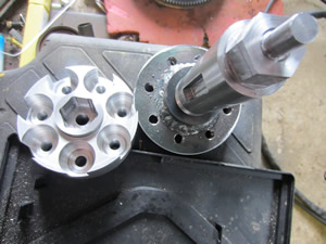
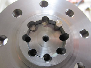
The bolts for the end of the crankshaft are 9mm with a really fine pitch, basically they're impossible to get. I had to use the original bolts meaning that I had to drill huge recesses to allow for a socket.
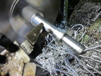
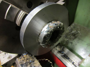
I pressed in the steel insert, drilled some holes, threaded and placed two grubscrews in each hole. This steel insert will later be milled as its the part that will allow the secondary engine to engage.
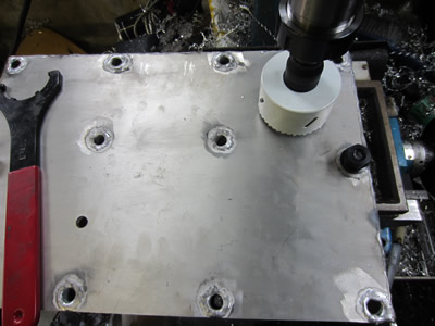
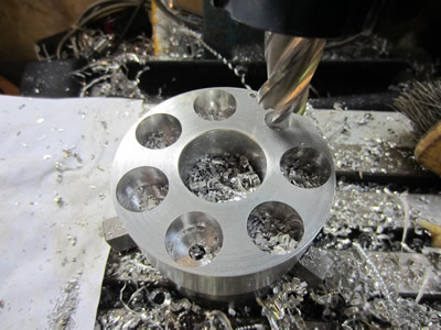
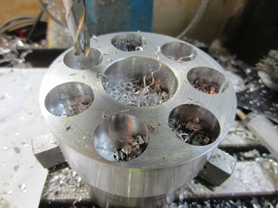
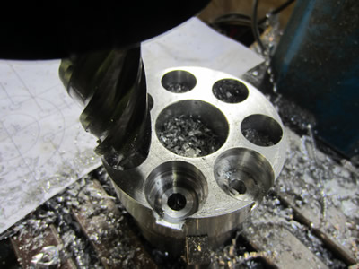
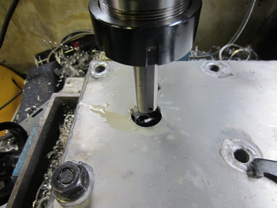
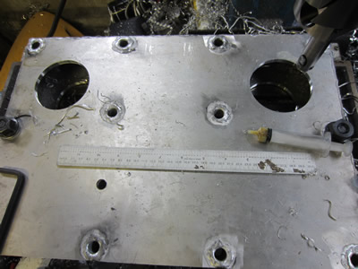
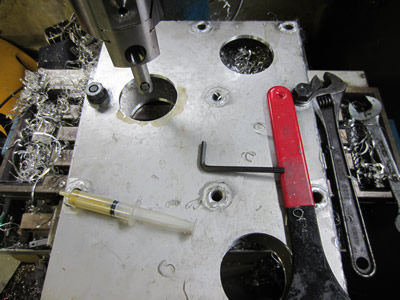
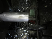
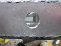
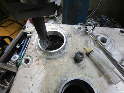
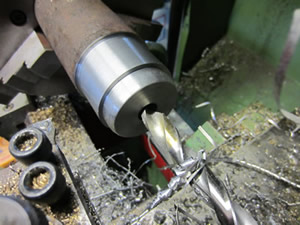
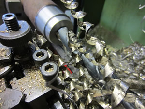
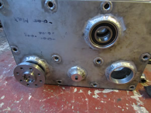
The chainbox requires three large holes to house bearings, I bought myself a hole saw to cut out most of the work but unfortunately it did exactly what I imagined it would do, vibrated, as can be seen in the second picture. The saw was a branded name, it wasn't particulary cheap either, but was poorly constructed.
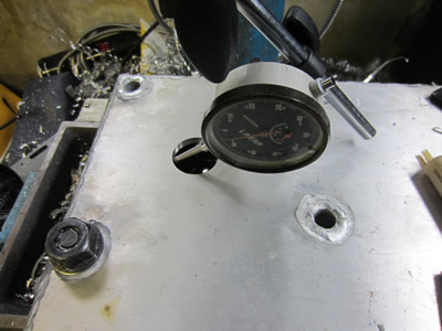
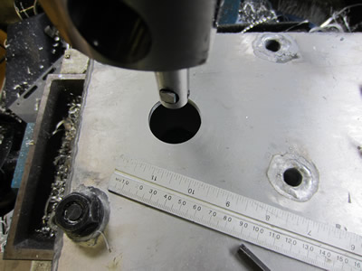
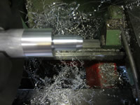
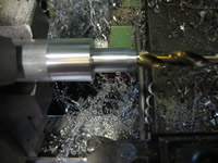
Instead I had to use a various assortment of milling cutters and then finally a boring head, it took quite a while but I got there in the end.
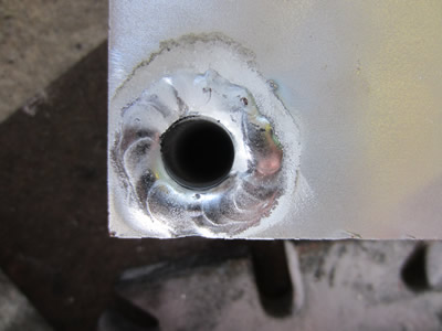
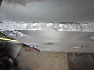
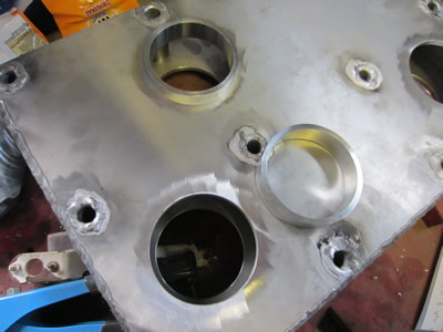
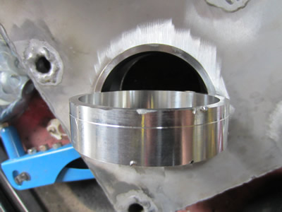
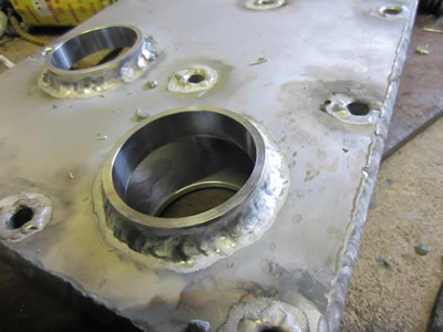
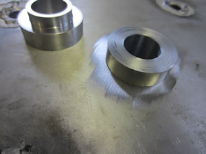
The plate for the chain box is only 6mm thick and therefore not thick enough for a bearing to house into it, so inserts were made which are welded in placed and then milled to the correct inside diameter at a later date to house the bearing. I had a little mishap when one of them fell against the chuck when parted off from the lathe, the insert was still fit for purpose. This time the welds were really easy and I feel they came out to a reasonably high standard.
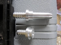
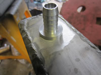
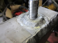
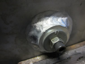
One concern I had with the oil being in a sealed box was cooling as there's not much in place to dissipate the heat, so I added some hose barbs that will connect to an oil cooling system, it also means that I can add a filter to remove all of the particles that degrade off the chain and sprockets over time. I made one barb longer that the other so that this one can squirt oil into the middle of the chainbox, probably not necessary but I might as well. When it came to drilling the holes in the end of the box I realised that it was too tall to fit into my miller, so I had to use a cordless drill and turn down the shank of my drill bit. Due to the box and drill not being rigid enough the hole came out pretty bad, thankfully it doesn't matter as it has been covered up by the weld.
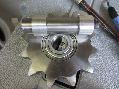
There is a total of four sprockets in the chainbox, two for the power transmission, one to tension and the other to stop the chain from slapping against the case. The idler sprocket already has a bearing built in which therefore means that no large holes are required in the chainbox. I bored out a hole through both sides to 25mm, made some inserts to fit in the plate and used a shaft through the middle to pull the inserts together for welding. The shaft is what's going to be used for the idler sprocket, I hope that the welding hasn't caused any distortion otherwise I may not be able to remove it, I will find this out tomorrow.
I have been having a lot of thoughts of how to build the ECU. Originally I was going to have four, two for the ignition on each engine and two for the injection on each engine, just so I could easily diagnose a problem if one was to occur. The program was to be saved in a programmable chip. I have had a different thought since then, there shall still be four ECU's but there will be no mapping program. Instead I will have a set of rotary switches that will control the advance and fuel mixture between each rpm range, the ecu will then average out itself between each range. I may sound a little over the top but this will allow me to map the car while its running which cannot be done with the chip.
July 22/07/2013 - Age 20
I had a feeling that I wouldn't be able to pull the pin from the chainbox, and unfortunately it took a lot of heating with a torch and lots of brute force. I remachined the holes again to allow the pin to pass through easily.
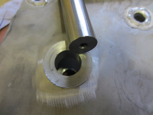
I made some spacers to go between the idler sprocket and the chainbox case. I also made some endcaps with a deep groove in the face of them to house an O-ring. The O-ring is to prevent oil from escaping, there is no seal between the bolt and the centre hole of the cap, the bolt on an aluminium surface should be sufficient.
I have also placed an order for a load of electronic components to aid with the manufacture of the ECU. I also bought some oil, oil filters for the engines and an oil filter for the chain box.
July 23/07/2013 - Age 20
Its been quite an action packed day, not quite as much of it on the engine as I would of liked though. I have bought some more metal for when I build the cradle for the engine and bought loads of bolts, washers and nuts. I received a call from one of my work colleagues saying that my laser cutting order has been cancelled - I used my works email. I phoned them up saying a mistake had been made and restored my order, some moron as a joke replied to one of my emails saying; "no, thanks" to my order. This has basically messed up my week as now I don't think my order will be complete before the weekend, the engines should have been completed by then.
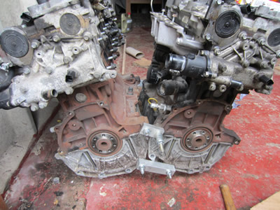
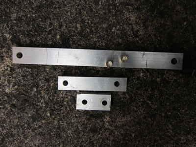
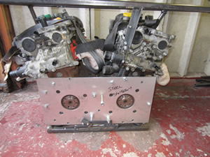
Since I won't be getting my plate in time, I have made some supports for the engine mounts that will pull the engines into position, this will allow me to build the cradle and test run the engines. The little brass inserts are to convert 13mm holes to 10mm holes. The long support is to connect the front of the engines via where the alternator pulley would be. Lining up the engines took quite a bit of effort, especially when just one of them nearly weighs double my weight, but I managed to lift and tilt them into place.
While in the process of removing the alternator pulley I uncovered that the water pump needs replacing on one of the engines.
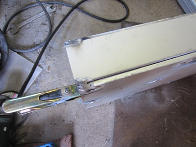
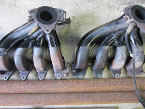
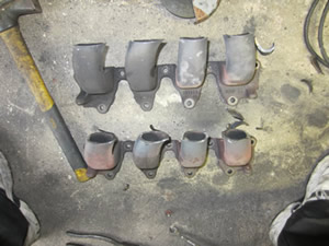
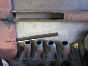
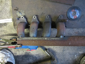
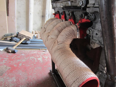
I was going to call it for the day but thought I would have a go at welding mild steel to cast iron, so the exhaust pipes were next on the list. At the moment I'm going for the easy option, maybe not the most power efficient or long term option. The welds turned out extremely messy due to the difference in materials, this led me to buy some exhaust wrap, I also need it to protect the inlet manifold from heating which would lead to a loss in power and efficiency. These pipes should sound amazing due to them being unbalanced and especially with them having no baffles.
August 05/08/2013 - Age 20
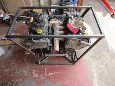 Its been a couple of weeks since I last updated this page. Firstly I built a frame to connect the engines together. Unfortunately I made one massive mistake, I really should have waited until my sheet was laser cut, without this the engines weren't in the position they should have been, even with the struts that I made. Luckily I only had to cut a few welds, atleast I could now move these engines around a bit easier.
I sprayed the exhausts in a high temperature paint, mainly to stop the welds rotting. I then wrapped them in a high temperature fibreglass wrap, it didn't take a huge amount of effort, but it was extremely messy. The purpose of the wrap is to shield the intake from the heat. The cooler the intake, the more power, the hotter the exhaust, the more power.
 I machined out the bearing housings and milled the top of the chainbox flat. The chainbox is now complete, all that is required now is to press in the bearings and make a sealing lid for it.
Today I phoned up the company that's laser cutting the engine mounting plate, amazingly they were just cutting it (I'm sure).
I have picked up a fuel pump and pressure regulator.
I have also bought a Jaguar S-type flywheel, clutch, gearbox, starter motor, prop shafts, rear axle including subframe, brake calipers and hubs. All for just £420 delivered.
I contacted a company about a week ago about a mapp-able ignition system, it came to a total cost of £680 which was a bit too expensive, I was possibly going to pay this if it was a quick delivery. I asked for a next day delivery which they said they could do but the lead time would be three weeks, which doesn't really make any sense. Instead I decided that I would make the whole ecu system, I have written the program, I now just need to get some encoders to measure the crank position. My goal is to get the whole of this project done in three weeks as there is a show coming up, I think that it should be possible.
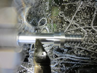
I received a piece of 35mm silver steel bar today that will be used as the output shaft from one engine to the gearbox, I did a quick bit of machining to prepare it for milling tomorrow.
August 06/08/2013 - Age 20
I bought myself a gearbox, clutch and rear end from a Jaguar S-type. Its was delivered today at a total cost of £420. The clutch has a dual mass flywheel, and the plates have a lot left on them which is great as a new set of these could cost between £600 and £800. The rear axle is a bit scabby and needs a good clean and a new lick of paint.
The aluminium plate which I ordered a long time ago was also picked up today, I'm really pleased with the results.
In my dinner time at work I machined a hex and a keyway on the shaft that will connect one engine to the gearbox.
August 07/08/2013 - Age 20
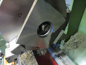
 At work in my dinner time I machined a socket, this will act like a spline that connects the flywheel to a clutch. In this case it connects the engine to the chainbox shaft. When I got home I pressed it into my aluminium housing.
August 08/08/2013 - Age 20
 In my dinner time at work I drilled out the key holes in the flywheel adapter, when I got home I tapped them and placed a grubscrew in each threaded hole.
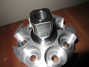
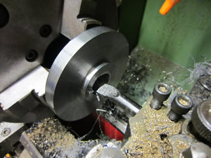
Also in my dinner time I milled a square on the flywheel adapter for the secondary engine. This part is for the secondary engine to engage or disengage, it will have a possibility of four angles to engage at. I will be able to determine what angle which will determine engine power or noise, I'm aiming for the best exhaust note.
August 09/08/2013 - Age 20
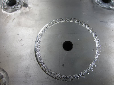
The only one thing I cannot do at home is use a dividing head, only where I work. The part I'm making is the adapter plate from my chain box output shaft to the flywheel. I had to make do with the material I had on hand, the pictures explain all.
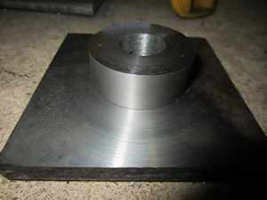
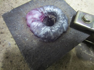
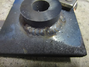
I made quite a large recess in one side of the plate, then filled it up with a really chunky weld. I did this to ensure that all will be solid, afterall it has to endure up to 350bhp. I then turned down this weld to the correct size to fit into the flywheel.
August 10/08/2013 - Age 20
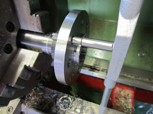
I wanted the adapter plate to be removable from the chainbox shaft, so I made it a press fit which will be keyed on. I didn't have time the night before to press the shaft into the adapter plate, I improvised at work which resulted in me squashing the smaller shaft after the hex, I also damaged the adapter plate. I managed to drill the holes that hold the flywheel bolts, then at home I tapped them to M10 x 1.0. I placed the shaft back into the lathe and turned the smaller shaft back to the 9.99mm that it should be. While at work I drilled and reamed some holes for the keys, then at home I made some pins to go inside. When the flywheel is bolted on it will prevent the pins from dropping out, including the addition of a ring. When a bit of torque is put down the shaft it may cause the adapter plate to shift slightly removing the slack in the pins.
August 11/08/2013 - Age 20
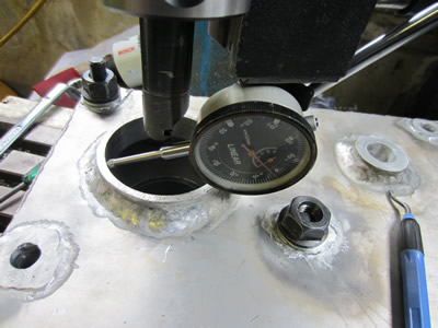
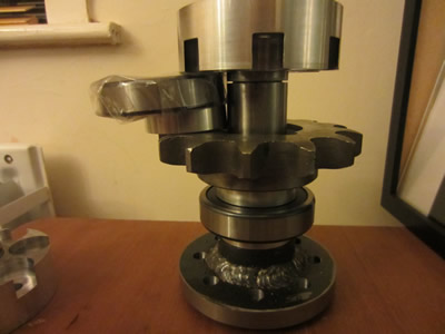 I pressed one of the spacers and one of the bearings onto the shaft that connects the primary engine to the gearbox and then loosely placed the rest of the parts between. Tomorrow I shall be pressing these into my chainbox housing and then connecting the chainbox to my engines. The reason for doing this is because I need to measure some spacers between the chainbox and the engine plates, I already know a theoretical value but need to make sure this is right.
I cut most of the welds on my engine frame and started from scratch, it took quite a while but I got there in the end. These engines are now ready for the chainbox and almost ready to run.
August 16/08/2013 - Age 20
Just a quick update, I pressed some bearings in the housing of the chainbox. One big problem that I encountered was the thermostat housings knocking into the chainbox, these will have to be modified.
The engine has now been put on hold as I bought a reliant scimitar today.
August 23/08/2013 - Age 20
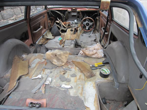
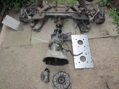
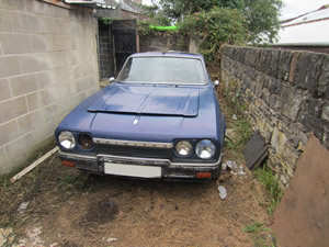 I got the car and decided for the time being that I would drive it around as standard, but first it needs a lot of restoration.
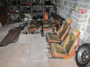
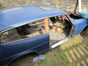
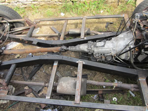
The engine and transmission are perfect, just the interior and the out-riggers on the chassis seem to be poor. I stripped the interior and the exterior.
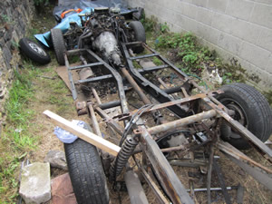
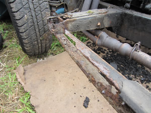
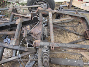
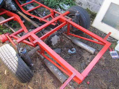
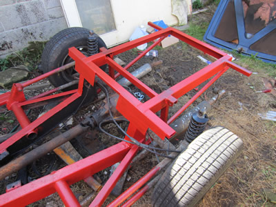
All the bolts that held the chassis on were rotten, they all had to be ground off. The shell was then removed at great difficulty to unearth how bad the chassis was. Some parts were really rotten such as the out-riggers and the back end of the chassis that houses the petrol tank. The main chassis was rust and rot free as were the front wishbones. I think in the past someone started to restore the car as all of the brakes were done, new shockers, poly bushes on the front, underneath wax-oiled, new exhaust system, new petrol tank, the only thing they didn't do was the welding as the body required removal.
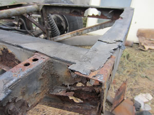
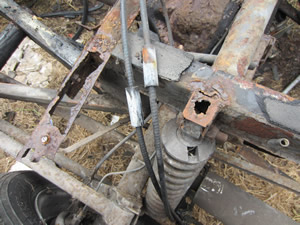 As you can see some parts were in severe condition, most importantly the rear shocker mounts.
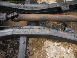
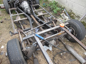
 The main chassis that bears the load is solid as can be seen to the right. Someone previously wax-oiled this part
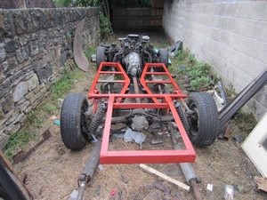
I started welding up the chassis using slightly thicker material and used box section instead of U-section, I also sealed the ends. The chassis is not complete in the last picture, I just started painting it to stop the welds from rusting. Note that in the last picture of the painted chassis it may look crooked, this is because I used wooden blocks the chock-up the chassis to stop it dropping when I removed the shockers, one wooden block is higher than the other.
October 27/10/2013 - Age 20
I thought it may be time for an update, a lot of the work done on the car was done in late August/ early September but due to weather, family and work its been a bit difficult. Anyway I finished off the chassis as can be seen in the pictures below;
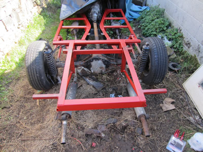
Now that all the welding has been done I have distinguished the need for power, which was the main reason why I could never get anything done on it due to it been outdoors. The one thing that I decided not to weld is the exhaust hangers, instead I'm going to use rivet nuts and bolt the hangers to the chassis instead. Another reason it has taken so long is because I ordered a rear brake line, that took a month to be delivered. So all I now need to do is fit the exhaust hangers, fit the rear anti-roll bar, the petrol tank and then the brake line. I can then put the shell back on.
It has given me a lot of time to think, basically I was going to restore the car back to its original state, then If I was to leave my job It could be sold. Unfortunately the market for these cars seems to be very uncertain, I may just break even if I were to sell it, plus I don't think I will be leaving my job anytime soon. Instead I'm going to have some fun with the car. I will be chopping the front end of the car and changing it to a front folding bonnet, this will make the overall body a bit lighter and easier to remove. The interior will be very basic, carpet and two bucket seats, and lots of toggle switches. The window seals are stupidly expensive, so these will now be bonded in. I will definitely be putting in the twin engines at some later date, infact due to the weather, the engines may only be the thing I can work on.
January 16/01/2014 - Age 20
Its been a long time since I did anything on this car, so now I'm thinking what I should do with the car. The first thing I'm going to do is to get the engines running properly, this mainly includes connecting the clutch and gearbox. This is going to include machining some new thermostat housings due to the chainbox. I will need to create a bell housing adapter for the gearbox to connect to the chainbox and some spacers between the chainbox and the engines. Once this has been completed I can then work on the ECU and run the engines. The ECU is going to be modular so that each section can be perfected such as the ignition or injection.
April 21/04/2014 - Age 21
This may be the last update for quite a long time. I'm not a fan of the person that is holding the car at the moment, but they owe me big time, so the car can stay there for a while, I may hire a unit out for a month or two to finish the car off in the future. I'm currently building a shed which means that my motorbikes can now go in this and the garage can be my workshop. The engines are at a different location, but can now be moved up to my workshop and worked on. I also need to learn a new programming language as the current chips I use are too slow for the ECU.
I would love to finish the project, I know the engines will get completed, but as for the car - I don't know. I'll see how circumstances pan out.
June 07/06/2014 - Age 21
I have built a shed which means that I now have more room in my garage, the engines will also be moved up to my garage as the resident has moved house from where they were previously stored. Once I have gotten my nuclear fusion project out of the way, which will be approximately another month or two, I can work on these engines. I have also had someone suggest using a little computer called a rasberrypi to run the ECU, it's like a very small compact computer that has the ability to run hardware.
June 29/06/2014 - Age 21
I have got the engines in my garage and work will start on them in approximately 2 months time. I've had a good think about the car, it's been stood for long enough and when I do complete it I simply don't earn enough money to insure two cars, so sold it. I will have a play with the engines and save them for the future, I want to prove my concept even if it's not in a car until a later date.
August 25/08/2014 - Age 21
Ok, so the engine concept is never going to happen. There are many reasons for this, part of this is because they are so heavy and awkward to move around. So instead I'm going to make something of just one of the engines, and use the chainbox to drive a large supercharger. The other engine can be used as spare for when this one is blown up. The whole thing will then be put into a cheap car, nothing special. This page has now ceased and therefore will not continue to be updated, check out the other projects.
Hello, if you have enjoyed reading this project, have taken an interest in another or want me to progress one further then please consider donating or even sponsoring a small amount every month, for more information on why you may like to help me out then follow the sponsor link to the left. Otherwise you can donate any amount with the link below, thank you!