Serial LCD
In the past I have bought two different serial LCD's from two reputable suppliers but found some faults and annoying features. Both of the displays had splash screens which only one allowed for it to be turned off but the procedure was rather awkward. One had a constant 9600 baud rate whereas the other was default at 9600 but was selectable in the software, which required 9600 baud, a design fault. The datasheets on how to configure these settings were also very difficult to follow. A few years after buying one of them it decided to exhibit stupid behavior and consequently I needed another, why buy one when I can make one cheaper that does everything I want it to.
At the bottom of the page there will be the option to buy the chip or as a kit, or you can continue to program the chip yourself but will require assembly. Chips, sets and boards will be available later 2016.
There are a few guidelines;
Baud rate is selectable externally via a dip switch - 1200, 2400, 4800, 9600, 19200, 38400, 57600, 76800
The splash screen can be turned off externally via dip switch
A new splash screen can be saved
A simple to follow instruction guide.
Easy way to write new characters
The chip I have chosen is the 16F628A as it has an adequate number of pins for both the display and the dip switches, it also allows a 20MHz running speed which is crucial for accurate baud rates. It is possible to have errors in both the transmitting and receiving end of serial, it is recommenced that either device does not deviate any more than 2% of the required baud.
Firstly since the program has been written for the 16F628A you need to know the pinout of the chip.
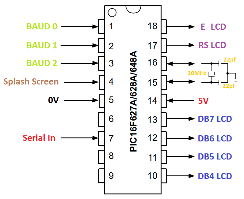
The pins on the chip need to be connected with their respectful place on the LCD, note that DB0-3 should be left blank or tied down to ground, the R/W pin on the LCD also needs to be tied down to ground. Pins 1 to 4 are inputs these require 10k ohm pull-down resistors, since they are all together at the end of the chip I would recommend using a resistor network. I would also advise using a 4-dip switch between these inputs and the positive rail to set the baud rate. Firstly I would recommend enabling the splash screen first as if purchased from me will contain a message, you will then know if the chip to LCD connections are correct, the switch is placed to the off position.
Once the chip is working correctly with the LCD it is now time to set the baud rate. Again set using the dip switches, the default baud rate of most devices is around 9600, so set the dip switch to position 110, from pin 1 to 3.
Pin 3 |
Pin 2 |
Pin 1 |
BAUD |
|---|---|---|---|
0 |
0 |
0 |
1200 |
0 |
0 |
1 |
2400 |
0 |
1 |
0 |
4800 |
0 |
1 |
1 |
9600 |
1 |
0 |
0 |
19200 |
1 |
0 |
1 |
38400 |
1 |
1 |
0 |
57600 |
1 |
1 |
1 |
76800 |
Once the baud has been set the module is ready to go, all the chip requires is an 8-bit serial input at the chosen baud rate to display a character.
Since serial is only 8-bit wide there must be some kind of protocol in place to determine whether a command is being received or the data itself. Note that it is possible to send 9-bit, the ninth is used as an addressing bit, it could be used in these circumstances but not all devices support 9-bit transmission. Both of the LCD's I purchased required the number "254" to be sent which sets the next data byte to be recognised as an instruction. This is quite universal for serial LCD controllers and I will keep this protocol, one of my modules also allowed "124" which is a little strange as this number represents a character whereas "254" does not. Another command I will include in mine is to set up the splash screen, this is "160" as it too does not represent any character. The control instructions will be exactly the same as those for the LCD itself to save on confusion.
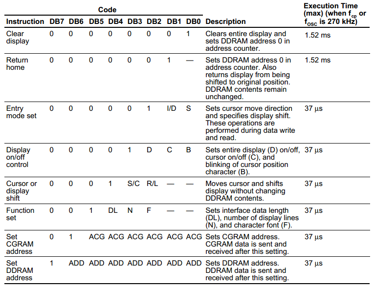
In the datasheet of a character display you will get something like the following which is the instruction set.
Writing the value "254" and then "1" would clear the display.
"254" and then "2" would return the cursor to the start position.
One thing to note is the execution time, clearing the display or returning to home are the only ones that require any time. This needs to be implemented into the transmit side of the serial, I do not want to complicate my program too much so this has to be done externally.
I have included the full set of instructions in the following table.
Here is the table for the instructions;
| Decimal | Hex | Binary | Description |
|---|---|---|---|
1 |
01 |
00000001 |
Clears display |
2 |
02 |
00000010 |
Sets cursor to address 0 |
4 |
04 |
00000100 |
Cursor direction - decrement. Display - not shifted |
5 |
05 |
00000101 |
Cursor direction - decrement. Display - shifted |
6 |
06 |
00000110 |
Cursor direction - increment. Display - not shifted |
7 |
07 |
00000111 |
Cursor direction - increment. Display - shifted |
8 |
08 |
00001000 |
Display - off. Cursor - off. Blink - off |
9 |
09 |
00001001 |
Display - off. Cursor - off. Blink - on |
10 |
0A |
00001010 |
Display - off. Cursor - on. Blink - off |
11 |
0B |
00001011 |
Display - off. Cursor - on. Blink - on |
12 |
0C |
00001100 |
Display - on. Cursor - off. Blink - off |
13 |
0D |
00001101 |
Display - on. Cursor - off. Blink - on |
14 |
0E |
00001110 |
Display - on. Cursor - on. Blink - off |
15 |
0F |
00001111 |
Display - on. Cursor - on. Blink - on |
16 |
10 |
00010000 |
Cursor Shift - to the left |
20 |
14 |
00010100 |
Cursor Shift - to the right |
24 |
18 |
00011000 |
Display Shift - to the left |
28 |
1C |
00011100 |
Display Shift - to the right |
32 |
20 |
00100000 |
Data Length - 4bit. Display lines - 1. Character fonts - 5x7 |
36 |
24 |
00100100 |
Data Length - 4bit. Display lines - 1. Character fonts - 5x10 |
40 |
28 |
00101000 |
Data Length - 4bit. Display lines - 2. Character fonts - 5x7 |
44 |
2C |
00101100 |
Data Length - 4bit. Display lines - 2. Character fonts - 5x10 |
48 |
30 |
00110000 |
Data Length - 8bit. Display lines - 1. Character fonts - 5x7 |
52 |
34 |
00110100 |
Data Length - 8bit. Display lines - 1. Character fonts - 5x10 |
56 |
38 |
00111000 |
Data Length - 8bit. Display lines - 2. Character fonts - 5x7 |
60 |
3C |
00111100 |
Data Length - 8bit. Display lines - 2. Character fonts - 5x10 |
64 + address |
40 + address |
01xxxxxx |
Character generator address |
128 + address |
80 + address |
1xxxxxxx |
Cursor address |
The initialisation stage in my program will set the standard defaults, these are;
| Decimal | Hex | Binary | Description |
|---|---|---|---|
40 |
28 |
00101000 |
Data Length - 4bit. Display lines - 2. Character fonts - 5x7 |
12 |
0C |
00001100 |
Display - on. Cursor - off. Blink - off |
6 |
06 |
00000110 |
Cursor direction - increment. Display - not shifted |
1 |
01 |
00000001 |
Clears display |
In reality there is very little that needs to be changed in the above settings, normally the exception is a smaller LCD that only supports one line. The cursor and blink are just irritating to see so generally never implemented, usually in few data input devices. Another exception is changing the display from 5x7 to 5x10 which would include sending the command "44", unfortunately this is impossible on most LCD's, infact it's quite rare to find a 5x10 one.
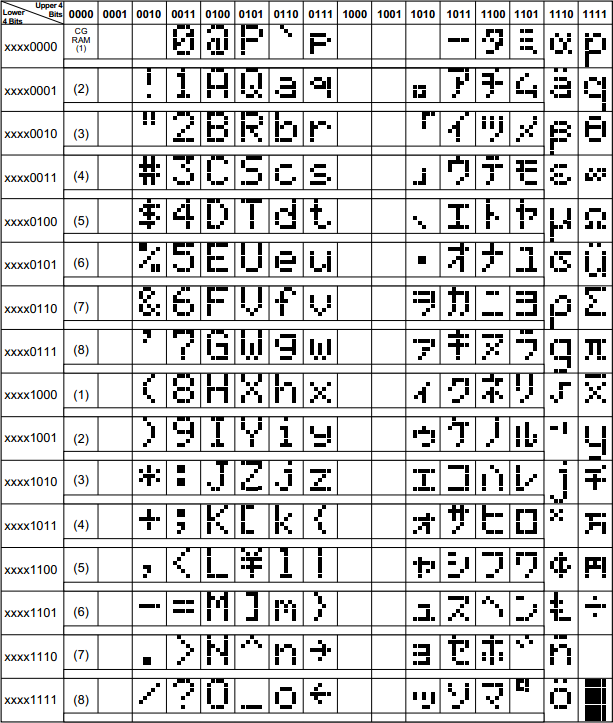
There are quite a number of characters that are standard to the display such as those to the left, these are known as CGROM.
So for example if I wanted to write the character "A" to the LCD then I would write the following binary "01000001", decimal "65" or hex "41".
All of these numbers and letters are known as ASCII (American Standard Code for Information Interchange) which when written in almost all compilers will be converted automatically. For example when writing zero in decimal to the display would bring up some specialised character. Writing zero in ASCII which is normally written as "0" will infact write the value "48" to the display, which in turn would present the character zero.
So what happens when you make some kind of a calculation in your program and you end up with a number such as 123. The number would have to be broken down into three digits, each digit would then be required to have the decimal number "48" added to convert it to ASCII.
What happens when you don't have the character that you require, you create one, up to eight can be stored in the display.
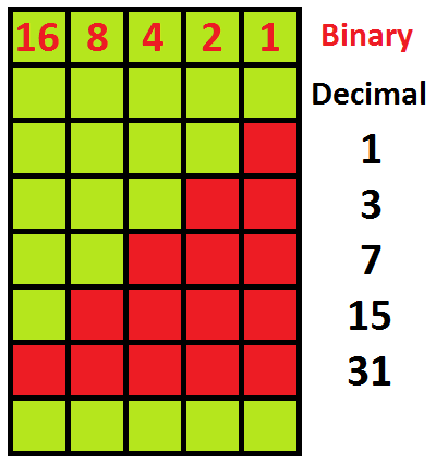
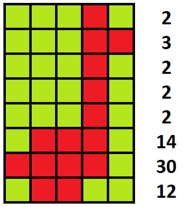
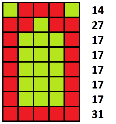
So how do you create a new character, firstly you need to know what your character needs to be. Even though the font in the function set is described as 5x7 the actual size of the segments are 5x8, the bottoms are missed off for the cursor. Firstly a matrix of the character needs to be created such as those below. As you can see you will end up with eight binary, decimal or hex values. I chose decimal as I find it easier to deal with.
Remember back to the function that sets the CGRAM address, this is used in conjunction with creating a character (CGRAM - character generation random access memory address). The size of the address is only 64-bit wide, each bit corresponds to a row of characters, each byte makes up one character and therefore there are eight characters total. When a character is created it is stored in the CGROM, where all of the other characters are stored.
| CGRAM address | CGROM address | ||
|---|---|---|---|
Decimal |
Hex |
Decimal |
Hex |
0 to 7 |
00 to 07 |
0 or 8 |
00 or 08 |
8 to 15 |
08 to 0F |
1 or 9 |
01 or 09 |
16 to 23 |
10 to 17 |
2 or 10 |
02 or 0A |
24 to 31 |
18 to 1F |
3 or 11 |
03 or 0B |
32 to 39 |
20 to 27 |
4 or 12 |
04 or 0C |
40 to 47 |
28 to 2F |
5 or 13 |
05 or 0D |
48 to 55 |
30 to 37 |
6 or 14 |
06 or 0E |
56 to 63 |
38 to 3F |
7 or 15 |
07 or 0F |
To create a character you must first set the serial LCD as command mode by sending the value "254" followed by "64" plus the CGRAM address. So for the first character I would send "64", the next character address would be "72" and so on. When this address has been set everything else sent as serial will setup the rows, so literally a string of 64 bytes can set all eight of the characters. If only one character needs to be saved then just a string of eight bytes will set the character followed by a display clear instruction will stop the character write mode. Now imagine I want to save the second character above in the third character location. First I would send "254", "88", "2", "3", "2", "2", "2", "14", "30", "12", "254" and "1". To display the character all I simply have to send is either "3" or "11".
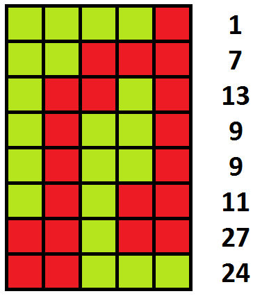
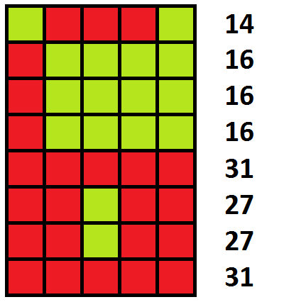
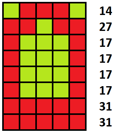
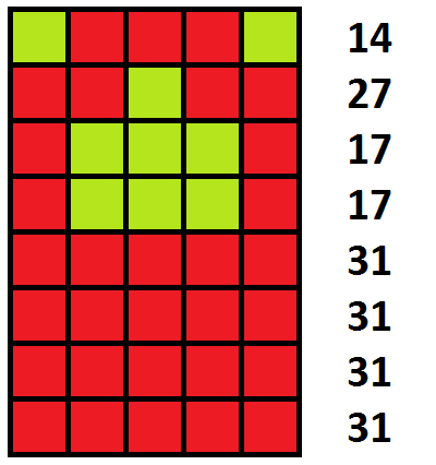
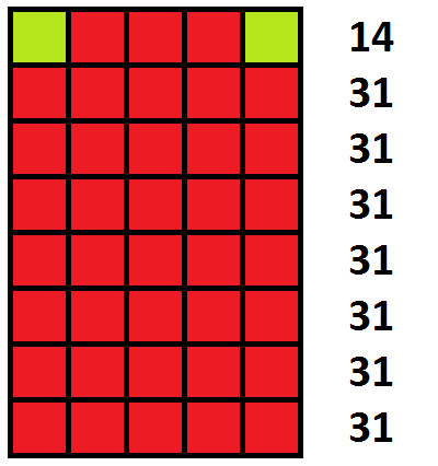
Here are another six examples of characters
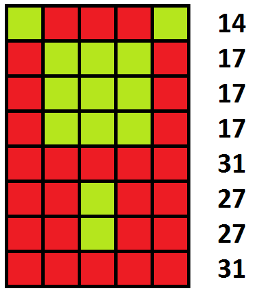
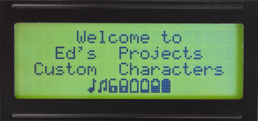
Here is an example of the custom characters.
One more thing to note is the position of the cursor, or where you want to write a character, this is known as the DDRAM address. The two lines in the LCD have the following address, in hex. It must be noted that the first line of addresses corresponds to row 1 and 3 and the second line corresponds to rows 2 and 4 of the LCD.
00 |
01 |
02 |
03 |
04 |
05 |
06 |
07 |
08 |
09 |
0A |
0B |
0C |
0D |
0E |
0F |
10 |
11 |
12 |
13 |
14 |
15 |
16 |
17 |
18 |
19 |
1A |
1B |
1C |
1D |
1E |
1F |
20 |
21 |
22 |
23 |
24 |
25 |
26 |
27 |
|---|---|---|---|---|---|---|---|---|---|---|---|---|---|---|---|---|---|---|---|---|---|---|---|---|---|---|---|---|---|---|---|---|---|---|---|---|---|---|---|
40 |
41 |
42 |
43 |
44 |
45 |
46 |
46 |
48 |
49 |
4A |
4B |
4C |
4D |
4E |
4F |
50 |
51 |
52 |
53 |
54 |
55 |
56 |
57 |
58 |
58 |
5A |
5B |
5C |
5D |
5E |
5F |
60 |
61 |
62 |
63 |
64 |
65 |
66 |
67 |
Or the table in decimal.
| 0 | 1 | 2 | 3 | 4 | 5 | 6 | 7 | 8 | 9 | 10 | 11 | 12 | 13 | 14 | 15 | 16 | 17 | 18 | 19 | 20 | 21 | 22 | 23 | 24 | 25 | 26 | 27 | 28 | 29 | 30 | 31 | 32 | 33 | 34 | 35 | 36 | 37 | 38 | 39 |
|---|---|---|---|---|---|---|---|---|---|---|---|---|---|---|---|---|---|---|---|---|---|---|---|---|---|---|---|---|---|---|---|---|---|---|---|---|---|---|---|
| 64 | 65 | 66 | 67 | 68 | 69 | 70 | 71 | 72 | 73 | 74 | 75 | 76 | 77 | 78 | 79 | 80 | 81 | 82 | 83 | 84 | 85 | 86 | 87 | 88 | 89 | 90 | 91 | 92 | 93 | 94 | 95 | 96 | 97 | 98 | 99 | 100 | 101 | 102 | 103 |
The LCD has to be placed into instruction mode and have value h80 or 128 decimal added to the above number to choose the cursor position. This is a useful way of reducing write time, it is a big help with data entry. The data "254" would be followed by "128 + address value" to choose where you want to start writing from.
I have written the program for everyone to use in assembly, below is a picture or you can follow the link to a text version here - Program.

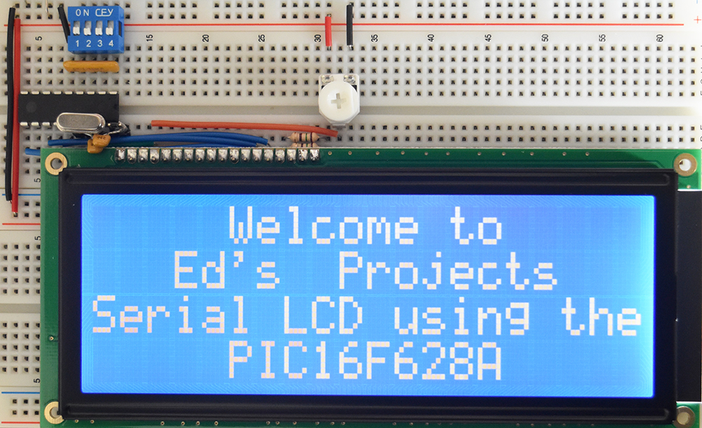
Below is an example of my setup of a breadboard, I chose to use a huge LCD which is 6" wide, actually same price as the smaller ones I've been using.
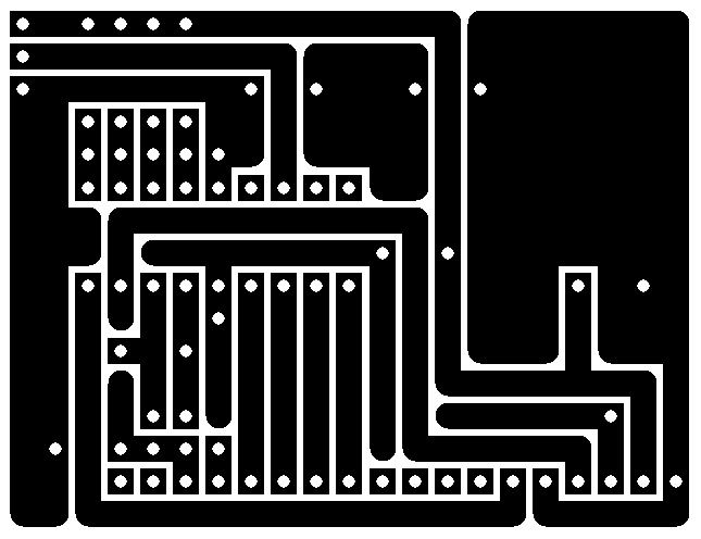
The software I have used for the PCB layout is "Express PCB", it's nothing fancy and does it's job ok for most designs however it is really wasteful when it comes to printing the layout design. The maximum size of board is 6" x 8" which is ok for most PCB designs but it will use a full A4 sheet of film.
The board is best developed using the photo-resist method and etched using ferric chloride. It is not always necessary to tin plate a board however it does make it a little easier to solder and prevents the copper from oxidising, it is however mostly a preference and I chose to do it simply because I have some tin plating solution. I have a page dedicated to the design and manufacturing process of PCB's, it is under my electronics page in the projects link.
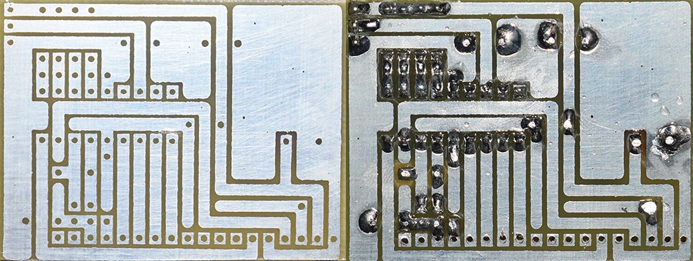
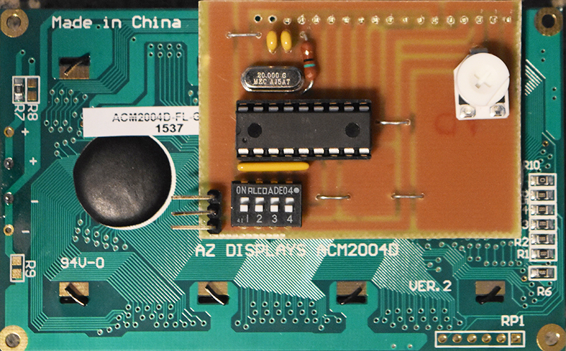
Here is the completed board with all of the components in place, I would certainly recommend using a socket for the main IC to allow for future improvements to the program.
In the near future I will give the option to buy these boards however they will likely be professionally made, dual layer with surface mount technology.
Hello, if you have enjoyed reading this project, have taken an interest in another or want me to progress one further then please consider donating or even sponsoring a small amount every month, for more information on why you may like to help me out then follow the sponsor link to the left. Otherwise you can donate any amount with the link below, thank you!