Asynchronous and SPI Serial Keypad
Back in many of my microcontroller tutorial pages I used a keypad which required a total of eight pins, it used a simple portion of code but nonetheless it needed to be constantly polled to check for an entered character. The fact is that most chips communicate via serial data transfer, sometimes it is easier to use several small chips each running with their own independent programs than one large one and having to cram it all together. I personally prefer to use asynchronous as it requires few pins, the only issue is that there is normally only one port on a single microcontroller. I keep the asynchronous port for LCD's and displays while I use the SPI port for everything else serial related. There is the option of I2C, however it tends to be slower but can be great for multiple devices.
For all purposes I will be creating a chip with asynchronous and SPI. The serial data will output everything as ASCII, for example the number zero on the keypad would infact be 48 decimal. The asynchronous chip will send data when written to it's register, it is a full-duplex system, so when the button is pressed on the keypad it is sent to the microcontroller, it is received immediately and normally initiates an interrupt.
The problem with SPI is that there is a master and a slave, only the master can initiate a transmission. So how do we know when a key has been pressed, well we don't to an extent. We first need to know a few factors such as the maximum speed of the buttons to be pressed and how accurate the timing needs to be for the master chip. When ever the master is ready for a keypad input all it has to do is send a message and see what it receives, if zero then the data is ignored. No data will be zero as we are transmitting ASCII from the keypad, for example the number zero is 48 decimal, zero will be written to the register after a transmission to ensure we don't send the same data multiple times.
The clock speed for the keypad chip is not all that crucial and I have chosen to leave it at 4MHz. It is only the asynchronous port that requires a specific frequency as the SPI module is run from the master chip clock.
The Hardware
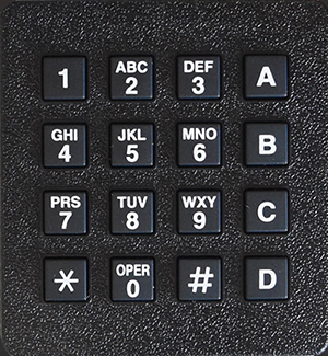
There are a few different styles of keypads to choose from, the majority of them will be split into rows and columns. Below is an example of the keypad I will use for this project, it is a 4x4.
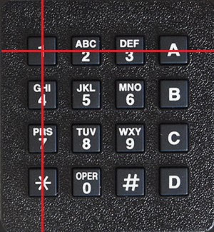
So how does this style of keypad work? Well for example we push the button one, it completes a circuit between row one and column one.
Imagine now that you connect all of column one to the positive rail, how do we know which key has been pressed, is it 1, 4, 7 or *?
To be able to determine which key is pressed we must only supply one column at a time, check all of the rows, power down the column, power the next column and so on.
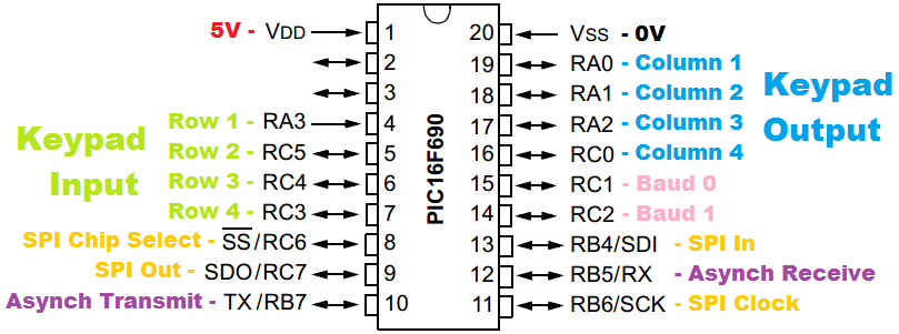
Connecting all of this up to a microcontroller is pretty simple, we connect all of the keypad pins to eight pins on the microcontroller. Four of the pins are configured as outputs to supply the columns and the other four are configured as inputs to check the rows. Below is a pinout diagram of the microcontroller I will be using. I have chosen to go with the 16F690 due to it's small footprint and it's SPI capability. A couple of baud rate control jumpers will add a little flexibility to the asynchronous speed, there are two spare pins on the chip, these were originally for a crystal but could be used as an additional two jumpers for the baud rate selection. Note the chip select pin will enable the SPI on this slave chip, remember the clock, data in and out may also be tied to other devices. The chip select pin is active-low meaning that pulling the pin positive will disable the SPI function on the chip, possibly when dealing with another SPI device.
Going back to one of my tutorial pages I use the inputs to detect a positive voltage signal, the output pins supply current one by one. The alternative is to set all of the outputs high and one by one low set each one low, place pull-up resistors across inputs, then when pressing a button it pulls the input low to indicate detection. Which one is the best solution? If you think about a microcontroller then you should know that inputs are CMOS, meaning they are capacitive and that "on" time depends on impedance. Is it easier to pull a microcontroller high or low? Again it depends on the application but generally there's little difference, it is normally chosen on power consumption. For this application I will choose to pull down the voltage, inputs will require pull-up resistors.
Software
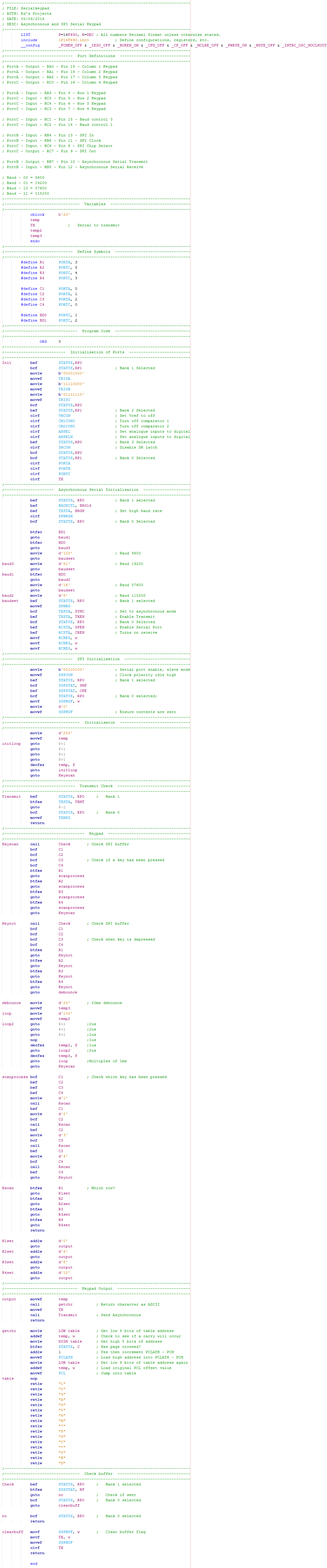
Now for the software, I have included the whole program and annotated it the best I can. The program will first check to see if a key has been pressed, if not it will continue to loop this small section. If a key has been pressed then it will scan each one by setting the columns low one by one while sweeping through the rows. Each of the columns load the working register with an offset number, when a row is detected it adds an additional offset corresponding to the row. We now have a number that points to which key has been pressed (1 to 16) which is then loaded to a lookup table to convert the character to ASCII. The value is sent out via asynchronous and also loaded into the SPI buffer. When the SPI buffer receives information from the master it simultaneously transmits it's contents, our variable from the lookup table is set to zero to stop us accidentally sending the information again. The buffer is cleared, when information is received it will flag a "buffer full" indicator which is polled every couple of clock cycles in the keypad scan, the buffer has to be cleared otherwise an overflow will occur.
Here is the program as a picture or here is a - Text Version
As proof of that this circuit works I have included a translator chip, the chip will translate the SPI and convert it to asynchronous to be sent to my LCD.
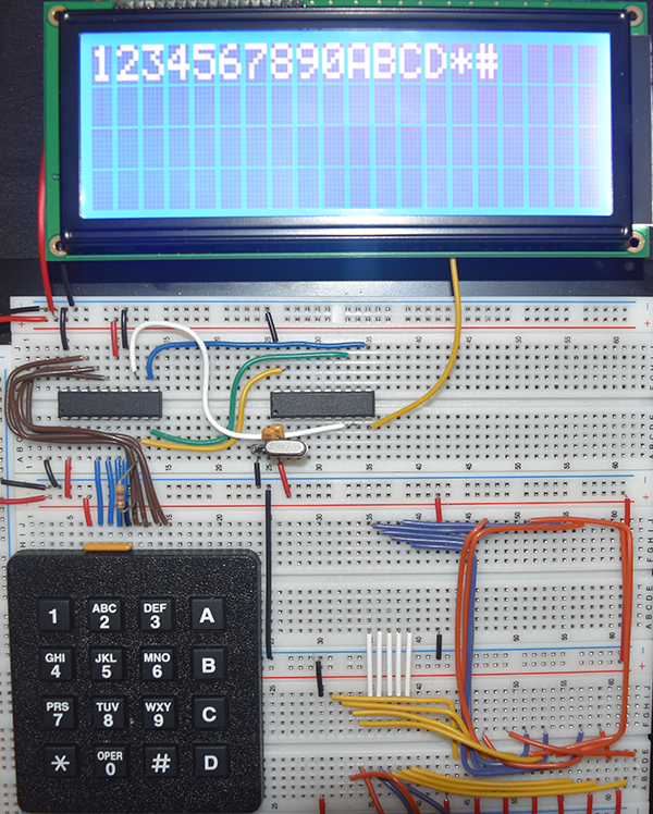
These wires on the far right of the board are from a previous project and should be ignored.
I hope that this small section may be of use to you in your project, please check out my other projects for more how to's or ideas.
Hello, if you have enjoyed reading this project, have taken an interest in another or want me to progress one further then please consider donating or even sponsoring a small amount every month, for more information on why you may like to help me out then follow the sponsor link to the left. Otherwise you can donate any amount with the link below, thank you!