How Fast Can a 3D Printed Gear Spin?
3D printing has allowed engineering grade materials and structures to be made at home. I want to know what material, gear profile and lubricating medium will be the best choice for high speed gears. Will a 3D printed gear be comparable in performance to one that has been machined, and, can it even out-perform it. This project will be to gain scientific data through testing every type of scenario, that will be thousands of gears. The majority of them I will 3D print, but I will also machine them too to see how comparable the performances are.
I will build a test setup that will measure each gears performance in the exact same way, I will quantify one of those particular sets of data in order to rate performance on a database. The idea will be to accelerate a set of gears to a maximum speed over a set period of time. I will measure the peak power but more importantly the highest speed and number of revolutions the gear makes before it fails. The number of revolutions will rank each gears performance which will be listed at the top of this page. I will include files so that you can print them yourselves, but more importantly this will help you determine the best gear for your project.
I will record the build progress of this project after the data table, there will also be videos of every single gear test. I need to pick a speed that will result in destruction of almost any gear, that ensures there is a quick end to the test. Please note I will be doing other types of testing in a different project, including torque, wear and tensile strengths.
The Data
Here is a table of every single gear test. Included are files so you can print them yourselves. After this table are instructions and specifications if you want to design your own gears for me to print, or even better, a mailing address so you can send me your gears to test.
None of these tests are sponsored unless otherwise stated.
| STL | Video Link | Profile | Pressure Angle | Helix Angle | Material | Lubricant | Print Parameters |
Max. Power | Max. Speed | Counts |
| Linky | Straight Spur | 20 Deg | 0 | Generic PLA | None | 220Nozzle, 60Bed, 100%infill, 0.4mm Nozzle, 3 Layer Wall, 60mm/s print, 0.18mm Layer |
577 W | 22,590 RPM |
11,012 | |
| Linky | 30 Degree Helical | 20 Deg | 30 | Generic PLA | None | 220Nozzle, 60Bed, 100%infill, 0.4mm Nozzle, 3 Layer Wall, 60mm/s print, 0.18mm Layer |
962 W | 15,120 RPM |
6,766 | |
| Linky | Straight Spur | 20 Deg | 0 | Generic ASA | None | 260Nozzle, 115Bed, 100%infill, 0.4mm Nozzle, 3 Layer Wall, 40mm/s print, 0.15mm Layer |
847 W | 34,090 RPM |
18,966 | |
| Linky | 30 Degree Helical | 20 Deg | 30 | Generic ASA | None | 260Nozzle, 115Bed, 100%infill, 0.4mm Nozzle, 3 Layer Wall, 40mm/s print, 0.15mm Layer |
1140 W | 30,737 RPM |
20,942 | |
| Linky | Straight Spur | 20 Deg | 0 | Generic PC+ |
None | 260Nozzle, 110Bed, 100%infill, 0.4mm Nozzle, 3 Layer Wall, 50mm/s print, 0.18mm Layer |
1220 W | 27,173 RPM |
12,761 | |
| Linky | 30 Degree Helical | 20 Deg | 30 | Generic PC+ | None | 260Nozzle, 110Bed, 100%infill, 0.4mm Nozzle, 3 Layer Wall, 50mm/s print, 0.18mm Layer |
1450 W | 19,531 RPM |
8,316 | |
| Linky | Straight Spur |
20 Deg | 0 | Generic PLA |
White Lithium Grease | 220Nozzle, 60Bed, 100%infill, 0.4mm Nozzle, 3 Layer Wall, 60mm/s print, 0.18mm Layer |
986 W | 22,865 RPM |
13,532 | |
| Linky | Straight Spur |
20 Deg | 0 | Generic PC+ |
White Lithium Grease | 260Nozzle, 110Bed, 100%infill, 0.6mm Nozzle, 3 Layer Wall, 60mm/s print, 0.18mm Layer |
744 W | 40,760 RPM |
21,227 | |
| Linky | Straight Spur |
20 Deg | 0 | Generic PC+ |
Shell Rotella Extra Tacky Grease | 260Nozzle, 110Bed, 100%infill, 0.6mm Nozzle, 3 Layer Wall, 60mm/s print, 0.18mm Layer |
976 W | 25,000 RPM |
9,268 | |
| Linky | Straight Spur 1% Scaled Clearance (Diameter) |
20 Deg | 0 | Generic PC+ |
None | 260Nozzle, 110Bed, 100%infill, 0.6mm Nozzle, 3 Layer Wall, 60mm/s print, 0.18mm Layer |
782 W | 33,482 RPM |
18,394 | |
| Linky | Straight Spur |
20 Deg | 0 | Generic ABS |
None | 260Nozzle, 110Bed, 100%infill, 0.6mm Nozzle, 3 Layer Wall, 60mm/s print, 0.20mm Layer |
1090 W | 44,642 RPM |
32,274 |
Results
I didn't run many tests until I realised that my setup is flawed, mostly in the fact that we're starting high torque, low rpm's at one end and ending up with low torque and high rpm's at the other end. It is clear from the testing that friction and heat make the largest variations in the results. Using a material with a high glass transition temperature and a lubricant with a low viscosity will yield the best results, as expected. Since I want to find the gear with the best high speed characteristics I must test just that. Instead of using several stages to reach the high rpm's I should use just one stage, that being a very high input rpm to begin with.
Lubricant
Lubricant has many uses, of course it's main use is to reduce friction. Lubricant can also dissipate heat, dampen contact pressure and reduce noise. I will try to demonstrate as many different types as possible, however to begin with I will be testing grease-based lubricants. Later I will add an oil pump so I can test all different types of fluids, such as water, oils, synthetics, etc...
No Lubricant - Plastics are often used where lubricant is an issue, however lubricant is better than none at all, this provides a control test.
Lithium Grease - A standard all-purpose white grease.
Silicone Grease - Often used for plastics and FDA applications.
Shell Rotella ET - Extra tacky grease. Mineral oil based, ok with most plastics.
Dry Graphite Lube - Sprays on.
Liquid Lubricants - Splash
This is the most common way in which a gearbox is lubricated. The gears themselves are partially submerged in lubricant. The gears hold oil between the teeth to transfer it to other gears, also the turbulence can achieve this too. Ideally the lubricant is minimal so that the least amount of friction is produced. The lubricant is often modified with "tackifiers" to keep it stuck to the gears.
Liquid Lubricants - Dry Sump
Any form of lubricant produces friction and resistance, especially on higher speed systems. A dry sump does best to make sure the gears have no submersion at all, a pump sprays the lubricant against the gears. Often a separate pump known as a "scavenge pump" will remove all liquid out of the sump to transfer it to a separate tank in which the lubricator pump is supplied from.
Water - This provides a good control test, almost no lubrication but does provide cooling.
Mineral Oil -
Fully Synthetic
Silicone Oil
Olive Oil
Note: Aerosol or Petroleum based lubricants can damage some plastics.
Drawings
If you want to design your own gears for me to test then this is the guide. Also note that while I would like to print your designs it may not be feasible, so once I can justify a PO Box I will post it here, all gears posted will be tested. All gears I test will be in the table above, so worst case you can modify or pull dimensions from those.
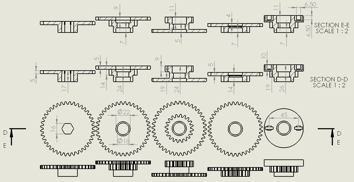
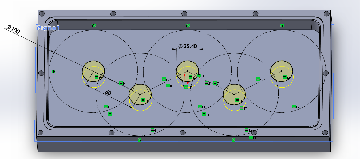
The pitch diameter of the gears is 120mm, or 60mm from centre to centre. That means if the first gear has a 90mm pitch diameter then the meshing gear must have a 30mm pitch diameter. The case is limited to a maximum gear diameter of 100mm.
Here are all of the critical dimensions of Gear 1 (left) to Gear 5 (right). What is most important is that the widths are correct so they have the right clearances between the other gears. The hex that fits onto the drive shaft has to be accurate to within 0.06mm and so does the 22mm dimension as this is for the ball bearing. It is also fairly crucial that the square for the magnet is large enough for it to fit, minimum 6.35mm. The diameter and profile of the gears can be left to your imagination, they don't even have to be round so long they mesh and rotate properly. I should add that I chose Mod 2 with 40 and 20 teeth, that is 80mm and 40mm pitch diameter.
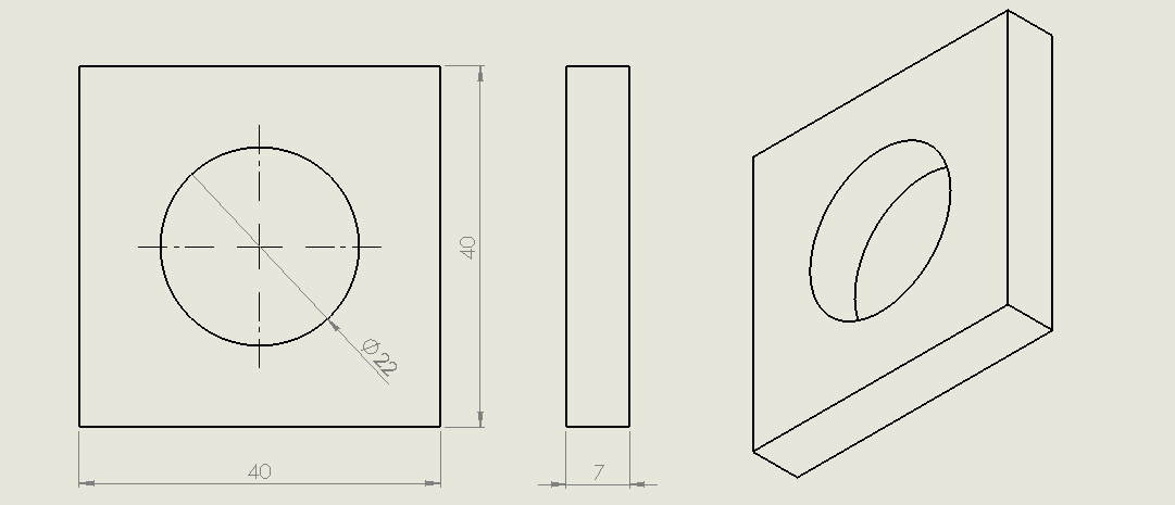
Lastly this is the gauge I use to get the dimensions correct without sacrificing a lot of material in the process. The majority of plastics will shrink to some extent when cooled. Mostly crucially is that the circle is 22mm as that is what will house the bearing, I would say a maximum of 0.08mm tolerance either way. Forcing a bearing into the gear will likely crack the plastic.
Note: Depending on how the parts are to be printed will determine if they have what is known as the "elephants foot". Often the very bottom couple of layers bulge slightly, or if using a raft there will be a burr present. In order for the gears to mesh properly and for the test to be valid, these parts of the gears should be "de-burred" or cut away.
Concept
I need to pick a particular speed that is fairly unrealistic for a gear to achieve but not in the realm of impossibility.
I need to make gears of sufficient size that 3D printer accuracy will not be of concern, I however can't make them too large due to manufacturing cost and time.
A set of gears to steadily increase speed without requiring too many parts.
A consistent way of testing each and every gear set.
A way of ranking each gear set test to place in a data table.
Design
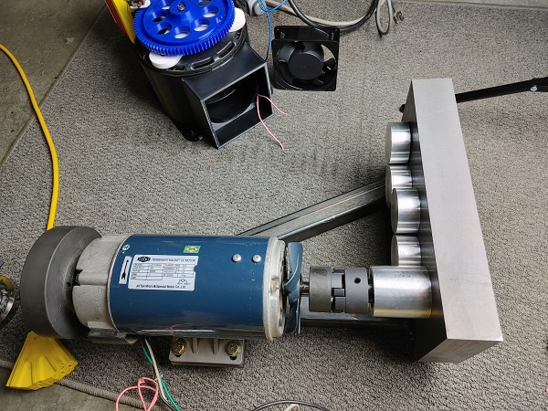
The very first step was to source a motor to spin the gears. A single phase induction motor is very convenient but it's speed is set, that means there will be a huge amount of power and torque required immediately. A three phase motor fixes the speed problem as it can be controlled with a VFD, but it is a fairly expensive setup. A brushed DC motor has a higher top speed, generally more torque for the size but will be subject to more wear. A very cheap solution is the electric motor from a treadmill as they typically run at 5000 rpm, lots of torque, power, but most importantly they are cheap.
To control the speed of a DC motor you need control the voltage, one method is a variac and the other PWM. Pulse width modulation (PWM) controls the voltage by switching it on and off very quickly, 50% on - off will yield half the speed of the motor, unloaded. Electronics are as weak or as robust as determined by the design, generally they are good, but expensive. The other solution is to use a variac / auto-transformer. The variac is a variable transformer that can change the outlet voltage typically anywhere from 0 to 120%. The current from the variac will be AC so needs to be converted to DC with a bridge rectifier. Variacs are generally very robust whereas the bridge rectifier again depends on its rating.
I picked up a treadmill motor rated 90VDC at 5200 rpm, 3 HP. I also had a 3kVA variac I bought a while back.
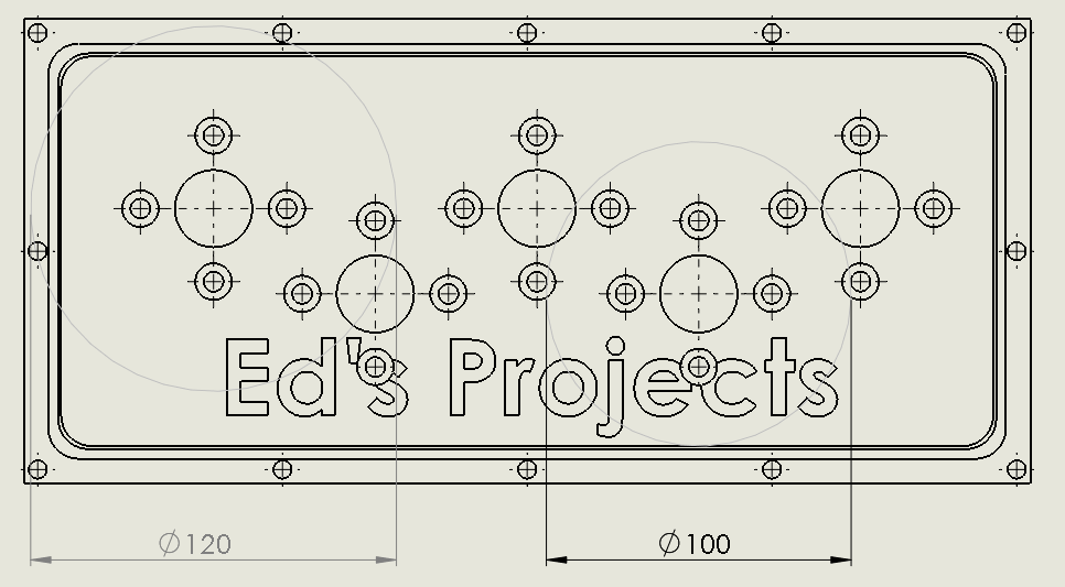
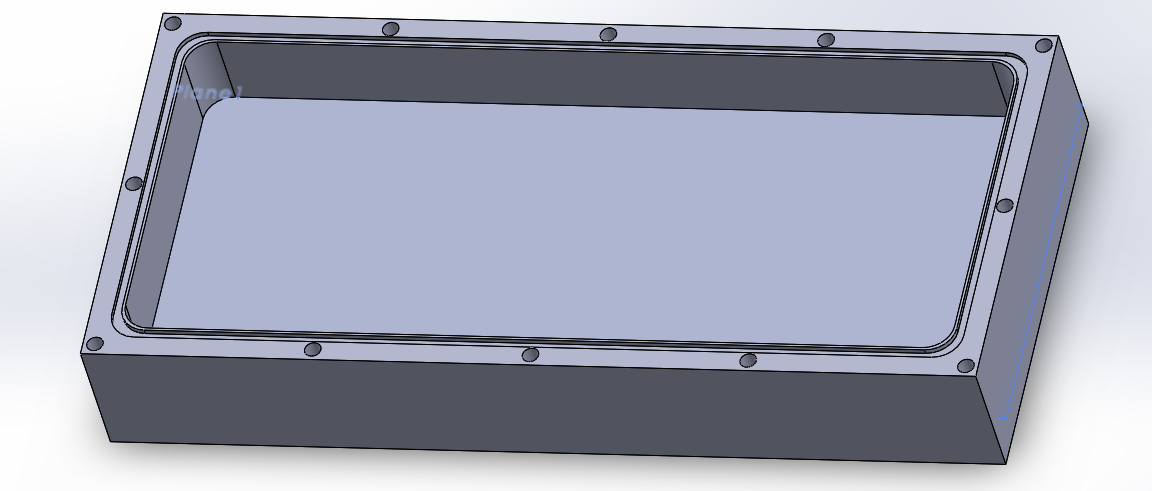
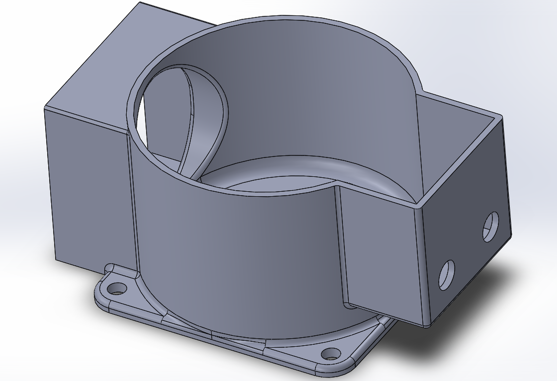
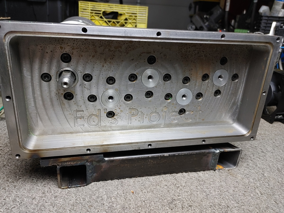
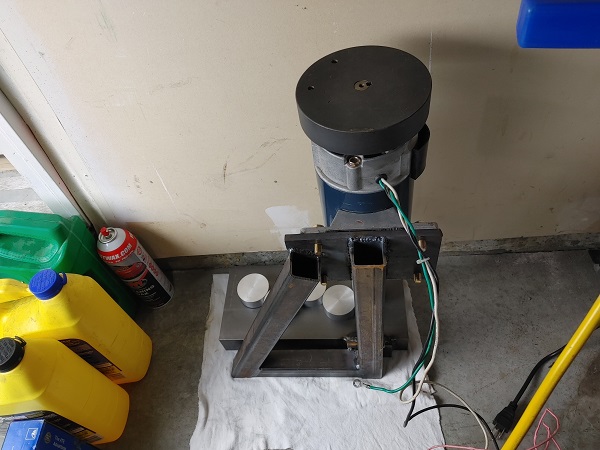
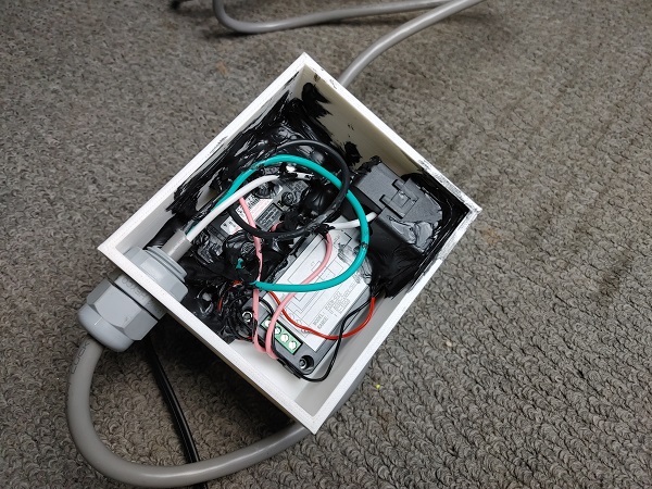
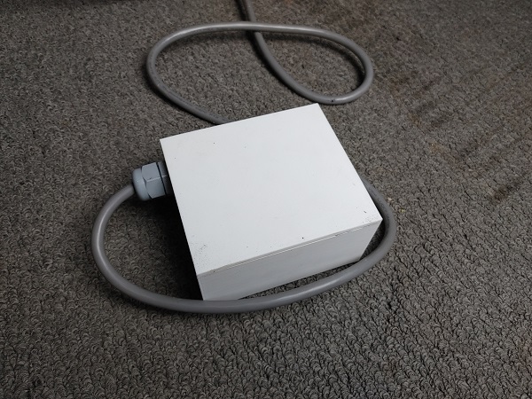
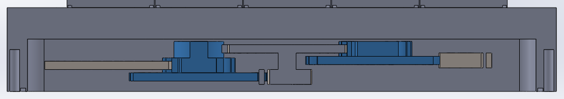
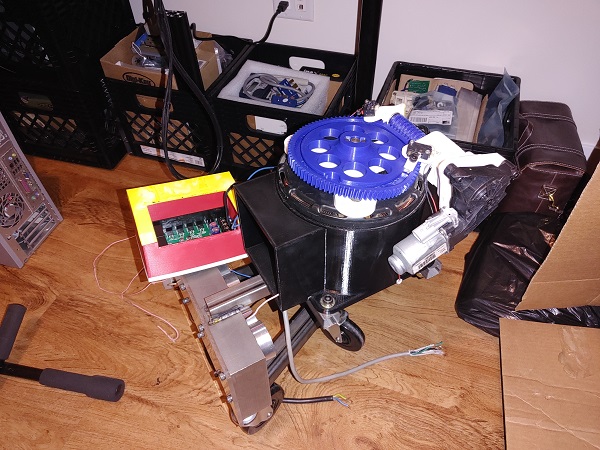
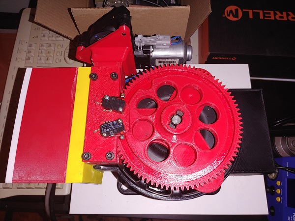
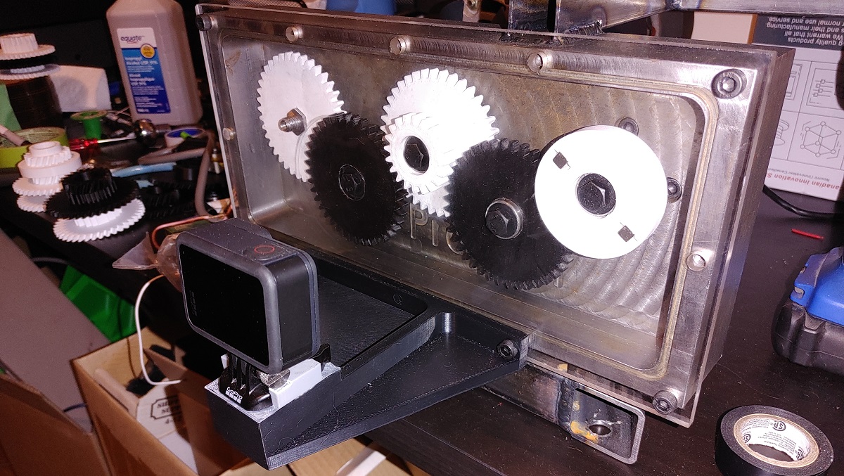
The next part of the design is to determine how large I want to make the gears and where I will be testing them. Since I want to test lubricants it means that it must be sealed. From another project I had a spare piece of 1018 steel dimensioned to 6 x 2 x 13.5 inches. I drew out the size of the steel and then made a cavity. The cavity was determined by the size of the screws to hold the cover and the groove for the O-ring. The screws are a common size and the O-ring groove big enough not to break my milling cutter, but small enough to maximise cavity area. The depth was decided by the length of the flutes on the cutter, 32mm in this case.
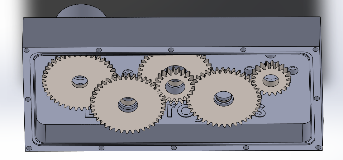
This next step was a bit of a doodling process that I did over a couple of days. I wanted to make sure I could fit a reasonable number of gears in the housing but make sure things would not clash dimensionally. I decided that the maximum gear diameter would be 100mm and the meshing diameter would be 120mm between gears.
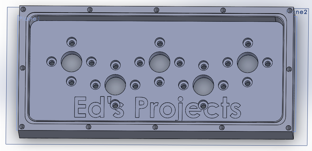
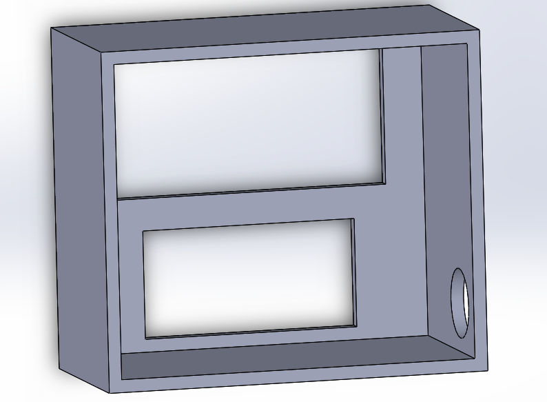
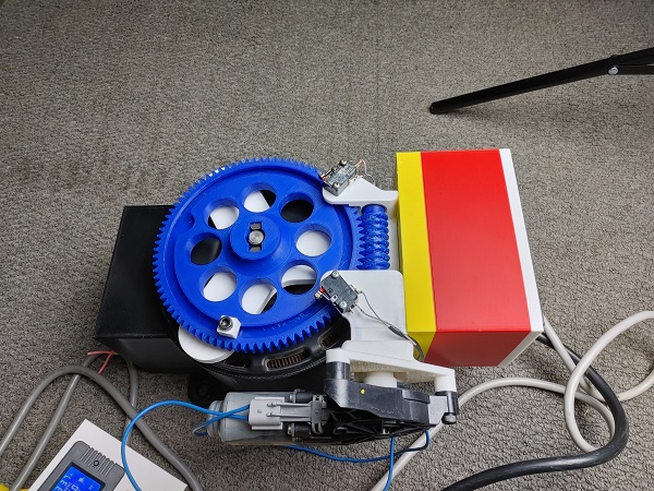
This is what I finally came up with for the housing. I of course wanted to include my website name if I was to be showcasing this on the internet. I also want to be able to use this housing for other tests so I chose to make it modular. That means that I can place output shafts connected to other things if I really wanted to. For testing these gears the very first hole would connect to the treadmill motor. The rest of them will secure the gears. The biggest advantage by going modular is to reduce costly errors, especially if there is damage done in testing.
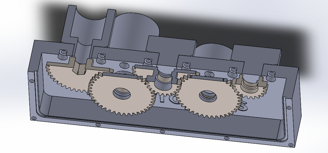
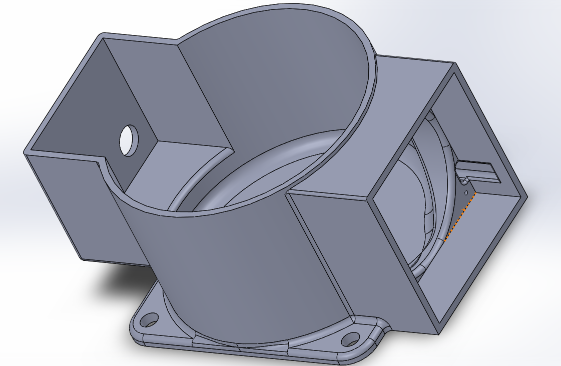
Here is how the whole setup needs to look, this is actually a sneak preview of some testing.
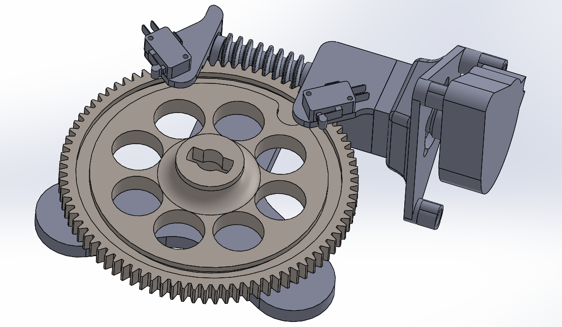
Next is controlling the variac to ensure it accelerates the voltage the same each time. This part took quite a bit of designing. The very first thing I did was test the speed of a motor, that is a geared window motor I picked up. I taped some paper on the output shaft and counted the revolutions over one minute, 75 in total, which equates to 75rpm. Now I want to turn the variac over it's full range in about 2 minutes, the full range is about 315 degrees, but lets forget about that. I designed a worm gear with a mod 2 pitch which would mean to convert 75rpm into 0.5rpm I would need a 150 tooth gear, that would be over 300mm in diameter. I instead went with a 75 tooth gear which would mean I'd have to run the motor at half its voltage, no problem.
Measuring up the mount for the motor and the variac was quite a task, especially for it to all fit together properly. I placed a t-slot on the gear so I could use some stops to press against the micro switches. The switches ensure I go back down to zero volts, but also ensure I hit the same top speed on every test.
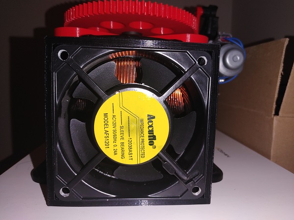
The variacs I got were all supposed to be chassis mounted which required me to make a case. I drew it up to see what it ideally should look like, I didn't expect it to fit in my 3D printer. I was quite surprised to find that it did, just. This case also incorporates a fan to keep the transformer cool, especially because I'm running it pretty hard.
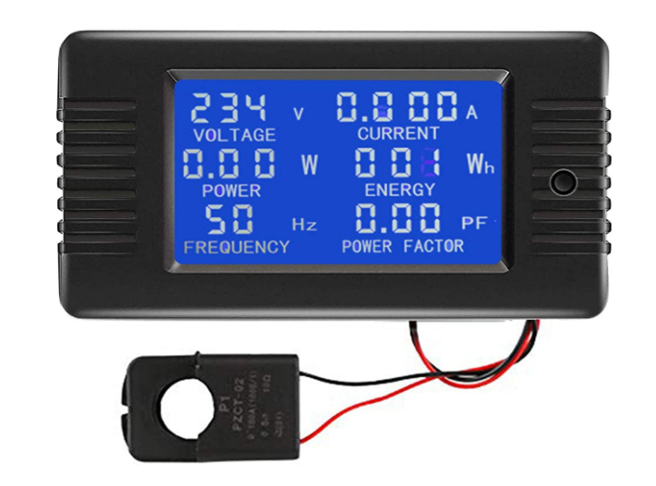
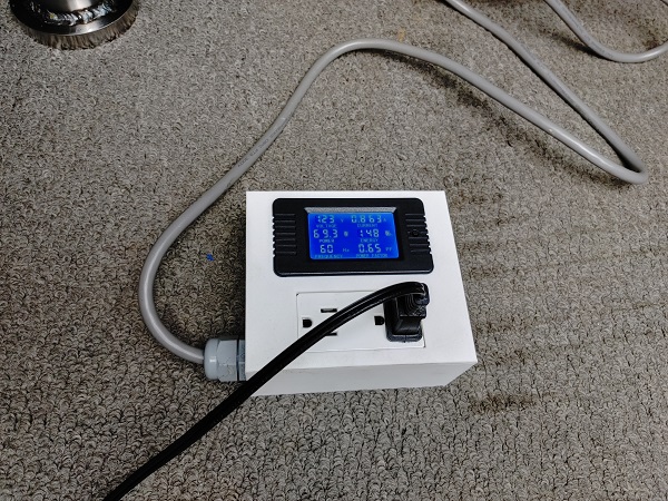
I would also want to test the input power since if some gears perform similarly in terms of duration then the one with the least power will be ranked higher. I did some searching around for the best power meter, I came across this one for very cheap. It will be interesting to see how it performs. The fact that it calculates the power factor makes me think it's reasonably decent. I'm not all concerned about accuracy but more consistency, which according to the reviews looks to be good.
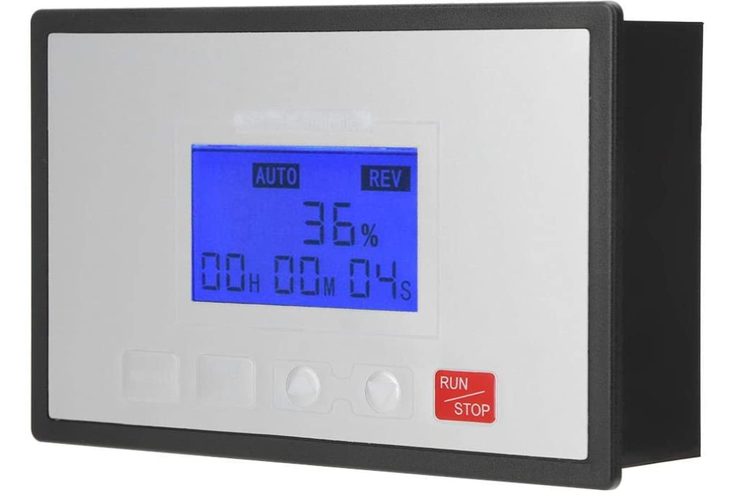
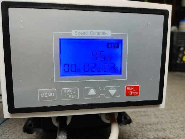
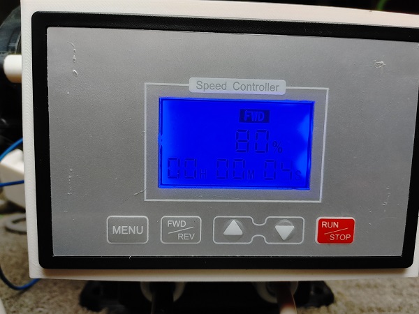
I also needed a way of controlling the speed of the electric motor for the variac. I managed to come across this which will modulate the speed of a motor, reverse it and most importantly has limit switches. I can control the forward speed independently of the reverse speed. It also records the time between limit switches, so I can fine tune it down to 2 minutes.
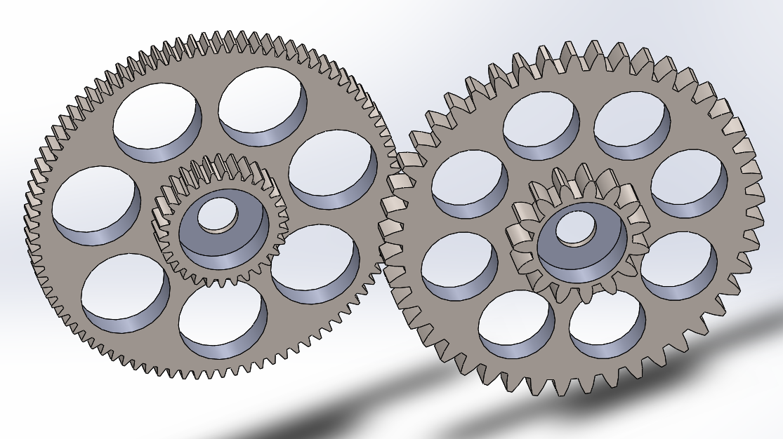
I did a lot of planning on paper in regards to gear ratios and dimensions of the gears. In order to do this I would need some kind of a goal, such as 250,000 rpm. A number that could be achieved with an input rpm of 8400 and gears with ratios of 1 to 2.33, that is 42 teeth to 18 teeth. I originally thought I could print all of the gears the same, but that was not the case as you'll read later.
I also need to make some kind of a counter for the final gear. I don't want to connect an output shaft as this will put extra load on the gears. I cannot use an optical sensor due to the lubricant. I will have to go with something like a hall-sensor, I just need to research how fast these can work since that's a frequency of 4.2kHz. The control part of the electronics should be pretty simple.
Prototype
I managed to take not a single picture of making any of this setup, so most of these are after it's been used. I did get lots of video though, so here is some adaptive milling of the cavity.
Here is the cavity finished with the modular inserts in place, the bearing will seal the fluid to the motor. Around each of the inserts is an O-ring to seal the fluid, the hole in the middle is blind. This picture is post testing with water as a lubricant, hence the light rust patches.
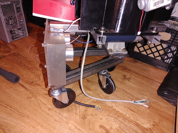
I mocked up a frame to hold the motor to the cavity, just to ensure the motor is fixed down correctly. I used a damped coupling for the motor since it is bolted firmly in place.
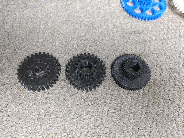
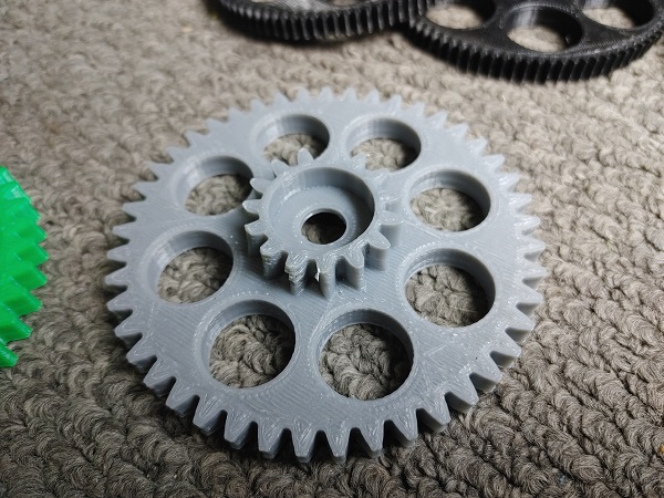
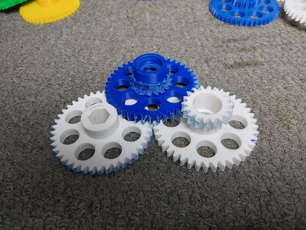
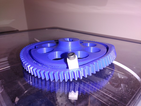
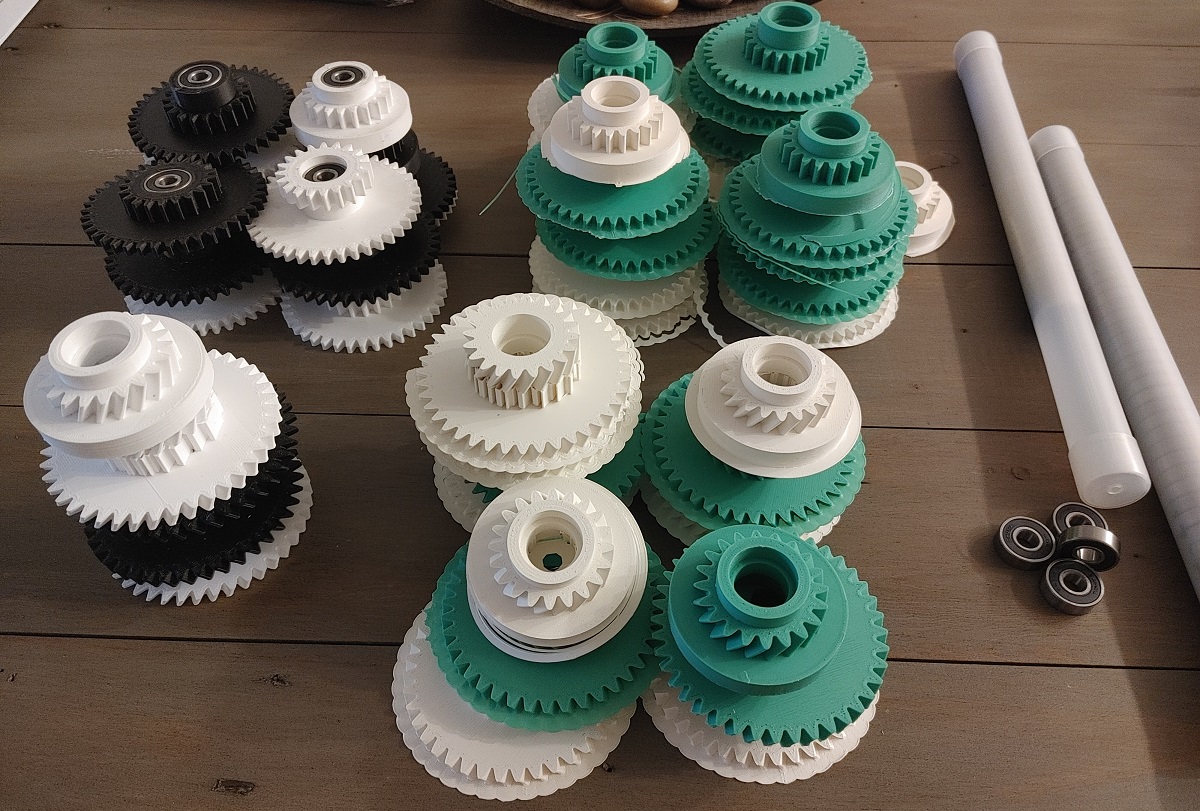
I spent quite a lot of time on the design side of things to find the correct gear dimensions. Here is an example of the very first set of gears to be printed, MOD 1 on the left and MOD 2 on the right.
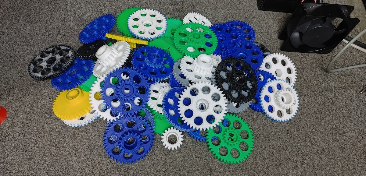
Here are all of the gears I designed and printed that didn't even get tested. These taught me a lot in terms of tolerances and how they should mesh. I had some big issues with my 3D printer which made me upgrade, the biggest issue was time. I upgraded to a printer with dual heads, better accuracy and a bigger print volume. I went from printing a single gear in 4 hours to being able to print six in 5 hours. I've always had an issue with this printer and its cooling, teeth are distorted in a particular position on each gear. The smaller MOD 1 gears are dimensionally really bad and don't mesh properly.
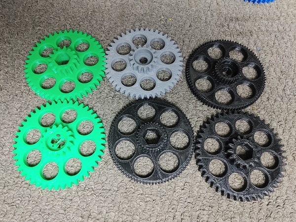
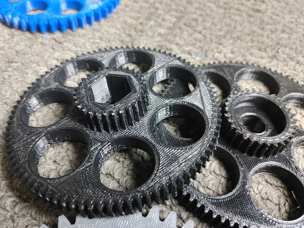
I switched to the easiest material to print, PLA. The great thing is that PLA barely shrinks, the bearing holes were within 0.05mm which was definitely not possible on my last printer, especially using ABS. The gears printed really good but did not spin all that great. The bearings are pressed into each side of the gears, a bolt goes through the middle to fix it to the housing. I did not use a spacer inside the bearing which to tighten the bolts correctly put far too much pre-load on the bearings. So I did some basic testing to find the bolts would just come loose. I instead used some washers between the inside of the bearings, this solved the issue and allowed me to bolt them down correctly. Here are all the gears I printed before I was happy with them dimensionally, there are about 15 that have been tested too.
This video is the very first test of my printed gears, it gave me a lot of useful information.
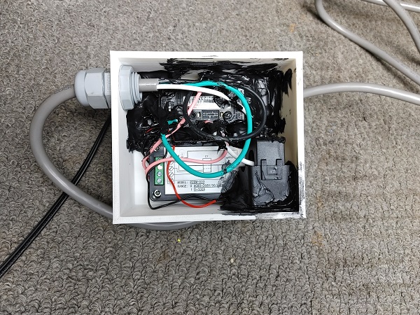
The first test was to see if the gears meshed properly and were dimensionally acceptable. I was quite surprised to see how fast they disintegrated at speed, more that friction melted the teeth rather than breaking them. I also got my power meter through the post so 3D printed this case to hold it in.
Here is the meter complete, thankfully it works great. I chose to use some old black silicone I had laying around to hold the socket in place, I later used some super glue.
I also got my controller for the variac motor. The case for the variac took around 45 hours to print, I chose PETG due to its better temperature rating than PLA. It took a bit of time to print all of the parts for the variac, but in the end it worked out and every part fit perfectly. It also allowed me to use up a few different used reels of PLA, the reason why everything is a different colour.
I did a couple of checks to make sure it worked correctly and set the PWM so that it would take two minutes for the full scale. Out of five tests each of them were within 3 seconds, excellent!
This second video was to test my automatic variac. I coated the gears in assembly lubricant to see what difference it would make, actually quite a lot.
The third test was to check the fitment of the gears with a cover over the housing. I originally had to space the gears from the housing with a washer and did not take this into account in my design. So when I placed the cover there was almost no gap between the gears and the cover. It caused so much friction that I could barely get them to spin. I shaved some material off the gears and made a note for the design update. For this test I added some water to cool the gears and did a couple of tests with different levels. The high speed footage was really impressive.
I gained a lot of research data from the last test which made me do a complete re-design of the gears. There is a lot of friction going on, so much that I hit the limit of my motor and variac. Reducing the width of the gears will reduce this friction, it will also decrease printing time. I also re-thought my goal of 250,000 rpm and changed the ratios a little. Instead of 1 to 2.33 I changed it to 1 to 2.0 which almost reduces the final speed by half, my new goal is 125,000 rpm. The less teeth a gear has the more localised heating there is on each tooth, also by reducing the larger gear it will reduce required torque, and reduce friction with the lubricant, even if that is air in some of the tests.
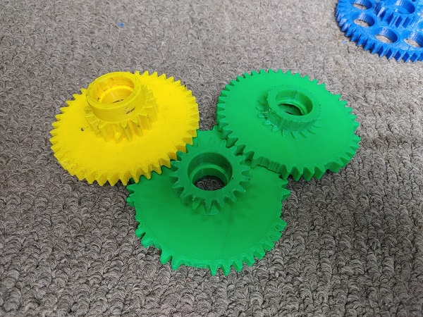
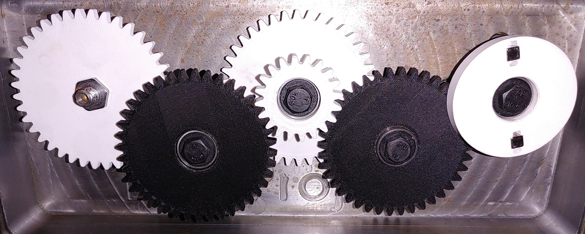
Here is a comparison of the gears I ran, those on the left dry and those on the right run with water. The idea of having contrasting colours is to see if material is transferred. Without coolant the gears melt and fail due to heat, you can see blue on the white gears and white on the blue gear. Running the gears with coolant made the difference in that they did not melt, they failed due to mechanical stress.
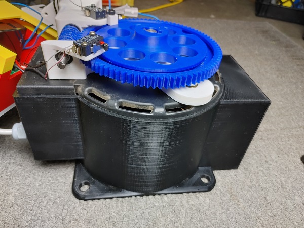
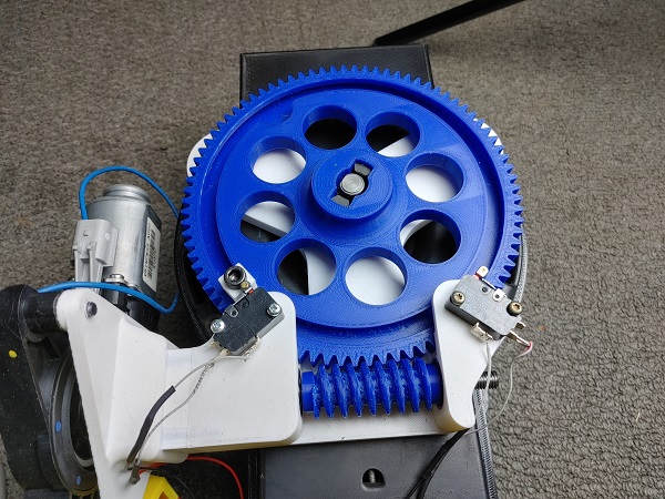
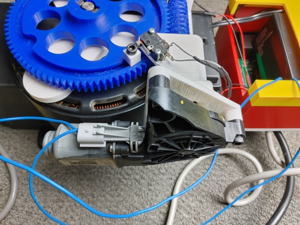
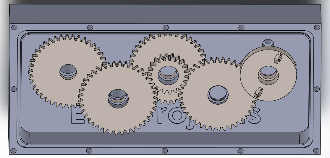
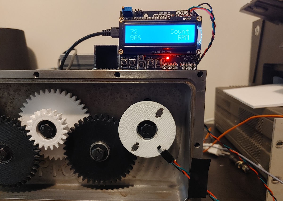
Here shows the new gears in their housing. I reduced the large gear width from 8mm down to 5mm and generally slimmed down the whole assembly. There is now plenty of clearance between the gears and the case. The last modification to make is something to measure the rpm and counts of the final gear.
Here shows a cross-section of how the gears will mesh together. The smaller gears have room either side for misalignment and tolerances. Having the smaller gear wider also allows the heat to dissipate better and also increases the strength of the teeth.
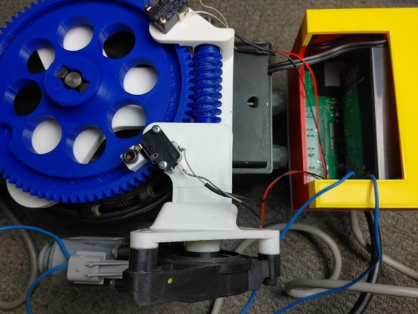
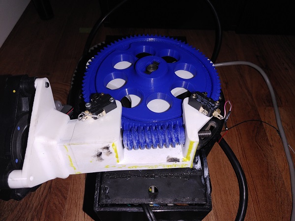
I did one more revision to the last gear so that it can hold two magnets for the rpm detection. The reason for going with two is to make it balanced as best as possible, I also made the pockets so the magnets can be removed easily. The gear is sufficiently close enough to the cover that if the magnets come loose they will not be able to fall out.
Here is the next set of revised gears, they are in contrasting colours, black and white so I can see if they melt or break.
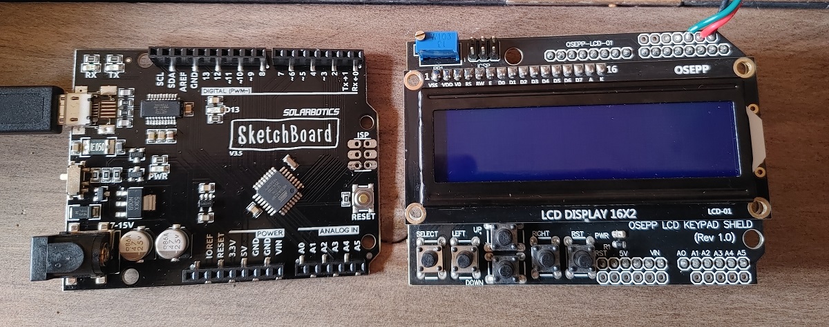
On a separate note I got some electronics to make the rpm meter and revolution counter. I wanted a quick and easy solution without having to design a circuit board or put something onto a strip board. I went with an Arduino Uno as the microcontroller and a display with buttons that fits on top, a modular system. I literally had zero knowledge about Arduino before buying one but I can now see why it is so popular. The microcontroller is an Atmel 328P which is the same manufacturer and similar data sheet layout that I'm used to, Microchip. The programming language is C++ and therefore compatible with C as I'm familiar with. It literally only took me five minutes to have the display working with a sample program and only about 30 minutes to write my own program for the rpm meter. Before all of that I first needed a sensor to measure the speed of the final gear.
I knew I could not go with anything optical because I will be using lubricant for some of the tests. I chose to go with a hall-effect sensor since I can place the sensor at a distance. I want the final gear to spin up to 125,000rpm, that is 2083 revolutions per second. Since I will be using two magnets I will need the sensor capable of 4.2 kHz. I found one out called the US5881 which allows up to 10 kHz switching frequency and a wide supply voltage up to 28V. The picture below taken from the Melexis data sheet.
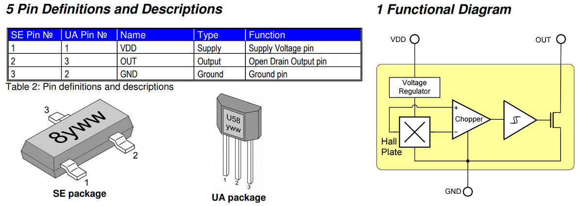
I next searched for the Atmel Mega 328P data sheet as I would need the register information to setup the timer. A timer is an accurate way of measuring the timing between events, more importantly it is a module that runs by itself in the background. An external event can interrupt the program at any point to start the timer counting, such as when the magnet passes the sensor. The external event can then interrupt the program again to stop the timer, the distance between these events can be used to calculate the rpm in this case.
The default speed of the microcontroller is 16 MHz and the timer can run at divisions of this speed. To work this out I need to know what the minimum and maximum rpms I need to work with. It is best to pick a number divisible by 60 as I need to work in seconds for the microcontroller and not minutes. So lets say 60 to 180,000 rpm which equates to 1 Hz to 3 kHz. The timer will be working in 16-bit mode which equates to a count value of 0 to 65535. If I pick a prescaler of 256 for the timer that means it will count at 62500 Hz, or I can pick a prescaler of 1024 which will count at 15625 Hz. Lastly since I am working over a duration of 1 second and the maximum count is 65535 then I want to pick the number closest. The largest number I can divide will yield a much better precision.
Since the prescaler of 256 will count 62500 times over one second it is within the 16-bit limit. So for example when the counter is started and stopped lets say it counts a total of 30,000 times. Our calculation would be 60 / (counts / 62500) to get rpm. So, 60 / (30000 / 62500) = 125rpm. Care must be taken as dividing a small number by a larger will yield a small decimal value, that will result in either a 0 or a 1 if using integers. Floating point values must be used to attain the correct result, but note these require much more time for the microcontroller to deal with.
Another option is to rearrange the calculation to (60 * 62500) / counts. It is likely that the compiler will rearrange the equation for us, but doing it this way means we can stick to integers and ideally let the processor deal with smaller numbers. Also note that because I am using two magnets the input frequency will be double. (60 * 62500) / (counts * 2) = rpm. Or 1,875,000 / counts = rpm. On a side note the meter will also count the number of revolutions. I will use the buttons to create an option to reset the results without having to power off or reset the microcontroller.
I spent a little bit of time writing a program. It records the highest rpm and the total number of revolutions, the user can also choose to reset these values. I'm not going to explain the program itself because it's very easy to follow.
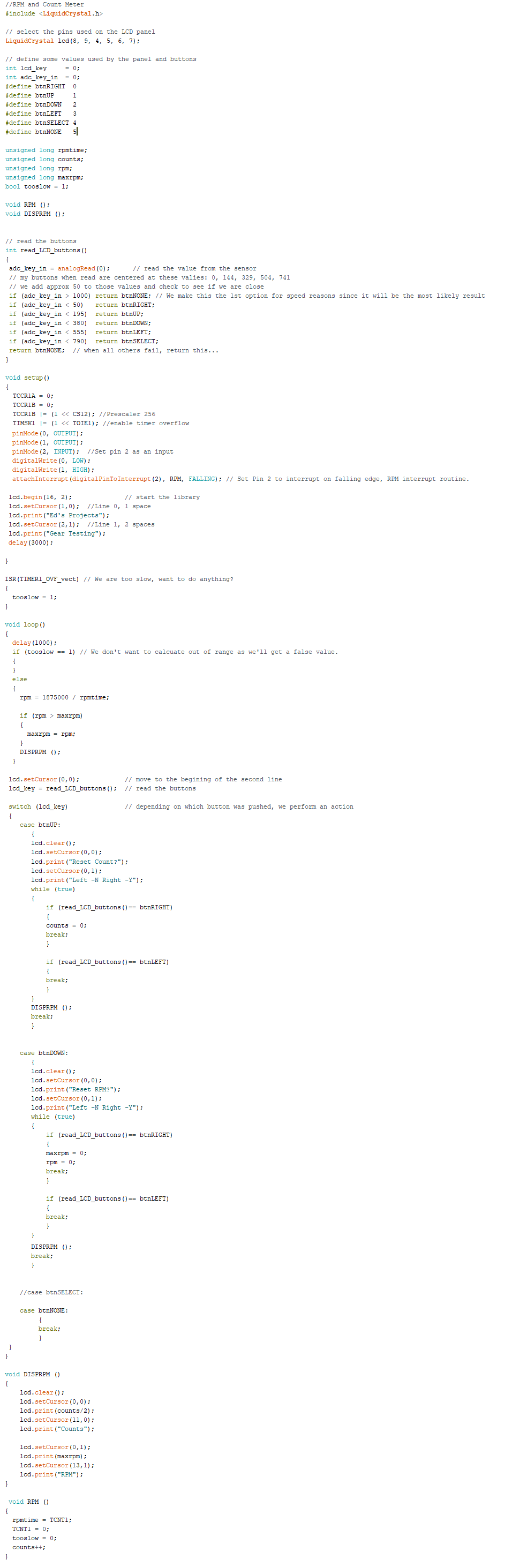
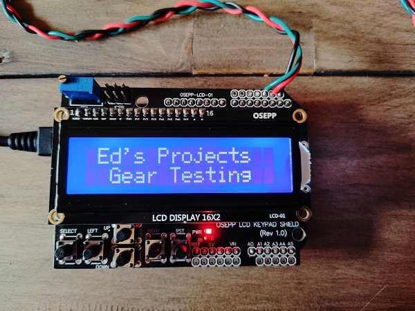
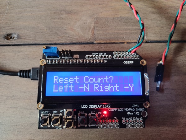
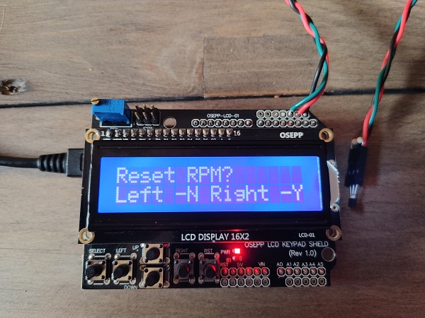
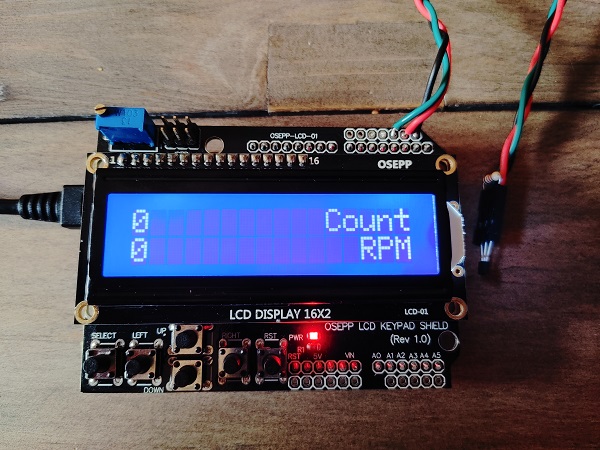
Here is an example of the splash-screen along with the reset options.
I gave the setup a try to find the cover was too thick for the sensor to respond. Without the cover it functioned perfectly and worked up to a gap of 6mm from the magnet.
I will modify the front cover so that it holds the sensor closer to the final gear, I might just drill a hole and use some kind of 3D printed insert. I have also been thinking about the lubricant and how I can reduce the friction, ideally not a splash lubrication system. I will modify the front cover so it has a sump to drain into, that way I can filter out anything that should not be there. I will modify the cover so that it will have sprayers between each gear, I just need to find a suitable pump first.
I had to move house part way through this project, including downsizing, so everything had to go in storage. Testing these gears is quite noisy so I made the decision to leave this setup in my car. The idea is I can bring a portable generator with me and drive somewhere I won't bother anyone. I had chosen to attach wheels to the setup and the variac to the top. However doing so made the setup really bulky to carry and move around. We were also having high heat at the time so when I came to take the setup out of my car a few days later things had changed. These are not the best pictures but they show it bulky, plus things got damaged.
I chose to make the main case of the variac from PETG so it could handle any heat produced, what I didn't take into account was the ambient heat. Everything else on the variac was printed from PLA which has a glass transition temperature of around 60 deg C. As you can see in the following pictures the parts warped so bad that they are now unusable, guess I'll have to print them again in PETG this time.
I spent a little bit of time reprinting all of the parts in PETG, with a slight design modification. Originally the stop switches were too far apart which didn't allow the variac output to go high enough. I also installed the cooling fan to keep things cool. The original control box was left in PLA and glued on again, time will tell if I need to print this out of PETG too.
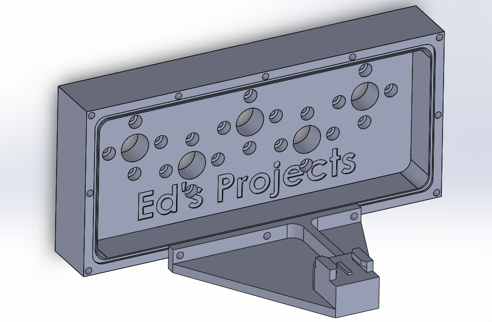
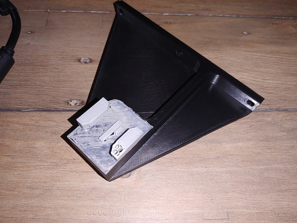
Another thing I should make consistent is how I film the test, so I chose to design a mount for my camera.
I printed it from ABS so it would not warp with the heat inside of my car. I knew I would be short of filament so I spliced some together, unfortunately ABS is the one material that doesn't splice all that well. It broke and skipped half a layer without me noticing, luckily I fixed it with some glue.
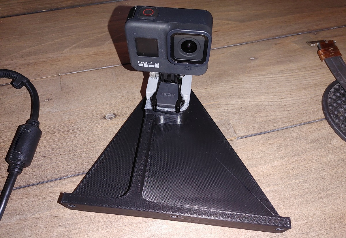
The camera is mounted on a quick-release so that I can remove the camera if needed.
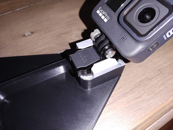
Here is it attached to the housing, the camera gets a full view of the gears.
The original idea was to do this testing in my car with a portable generator, still not sure if I'll do that or just wait until I take possession of my unit. In the mean time I thought it would make sense to take several sets of gears with me. I chose a really common size of bearing for the gears which means they are also cheap. I purchased 100 bearings so that I can take 12 sets of gears with me, if needed. To pull the bearings out of each test is time consuming, so that is something I can do later. Here shows plenty of gear sets ready to be de-burred and the bearings inserted.
Note: Depending on how the parts are to be printed will determine if they have what is known as the "elephants foot". Often the very bottom couple of layers bulge slightly, or if using a raft there will be a burr present. In order for the gears to mesh properly and for the test to be valid, these parts of the gears should be "de-burred" or cut away.
Some of the gears will require a raft to ensure the teeth do not warp when printing, something I will have to do for many of the materials, as shown in the above picture. I have to de-burr every single gear to ensure they mesh properly. Without removing this part which otherwise puts the gears teeth out of tolerance it also requires that the input motor works harder. This can skew the results by creating extra friction.
The very last thing to do was drill a hole in the acrylic cover to place the RPM meter sensor. I also had to solder wires to the sensor instead of using a connector since it could skew the results.
Videos
Since there are so many videos I will have to embed them on a different page, there is also the option of following the link in the data table.
I have done some tests on posting different videos on Youtube to see what attracts the most attention. I also take note of all the videos I watch and also why I don't watch them. It also seems that once you establish a following you can just post junk, unfortunately. Most important is keeping the viewer interested, often that the stakes must be increasing and they are expecting something to happen. People really don't want to sit through dialogue when nothing is happening, even if it is putting context to what you're about to watch.
I must be able to explain what I'm doing, represent all of the data and keep the format consistent while maintaining interest. My test will accelerate the gears to maximum speed over the span of 2 minutes. I predict that the majority of tests will survive for the first minute, many not much after that. If on the off chance the test continues for longer than 2 minutes then I'll keep going until a failure happens, that is likely to be soon. I figure that If the test starts immediately then I have at least 45 seconds of text explaining the setup and parameters. After failure I can then play some slow-motion while I present the results. I also need to have a screen to display where these results can be found along with the corresponding files.
Ultimately I need a video that has constant action while text gives it context.
Conclusion
I hope this was an interesting project, the videos being a lot more interesting. Ultimately my method of testing was flawed and it required a huge amount of time for the 3D prints. I will continue with this project again, but this time I will introduce a much higher input rpm and test just two gears meshing this time.
Hello, if you have enjoyed reading this project, have taken an interest in another or want me to progress one further then please consider donating or even sponsoring a small amount every month, for more information on why you may like to help me out then follow the sponsor link to the left. Otherwise you can donate any amount with the link below, thank you!