Hyundai Tiburon - Turbo Conversion - Oil and Cooling
At the current time of writing this (March 2018) my Tiburon is my daily driver but also my modification platform. In the near future I plan to develop my own ECU system mainly so that I can cheaply modify cars as part of a side project. The main idea of modifying these cars is to turbo them for cheap while making them reliable, the only way to do this is to make the parts myself. This project is the second stage in converting my Hyundai Tiburon to turbo, this will concentrate on the oil and cooling side.
The Design
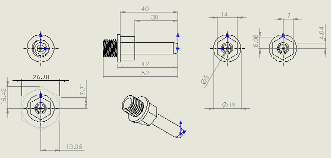
The first step was to make a design for the hose barbs for the oil inlet, the coolant inlet and coolant outlet. The size of hose will be 1/4" for them all, the oil will be thread size M12 and the coolant M14. I first started by designing the barbs in Solidworks so that I would have something to work from when I manually program them in the lathe, the actual barbed part for the hose will be stolen from a previous program that I used to machine some fuel line barbs.
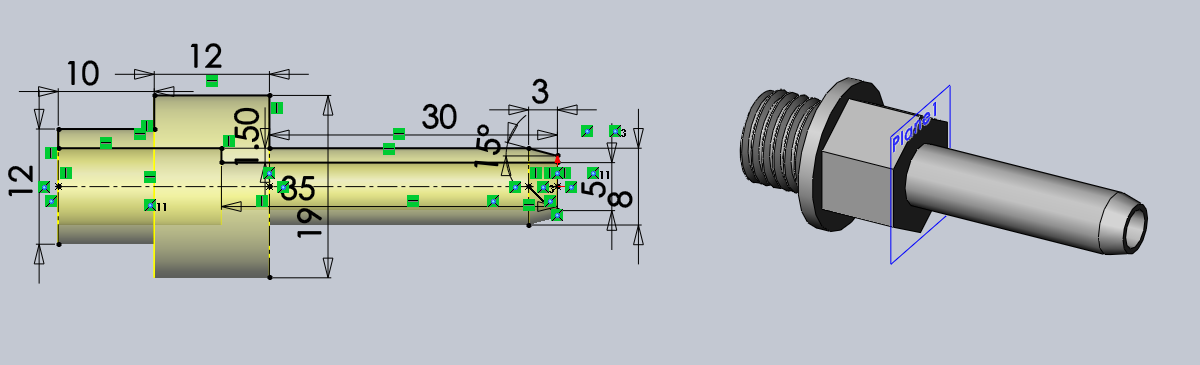
I printed a drawing with all of the major dimensions, this will aid in programming.
The Build
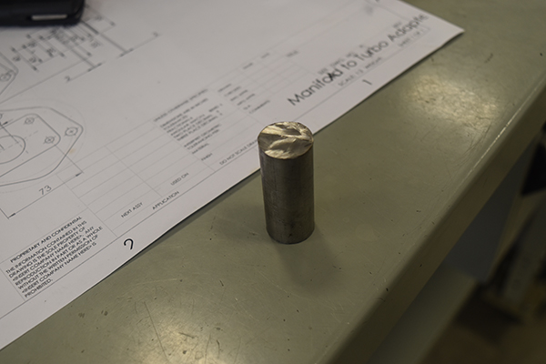
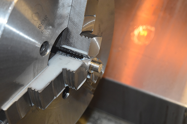
I started by cutting seven slugs of 3/4" 304 stainless at lengths of 54mm, I then proceeded to machine them.
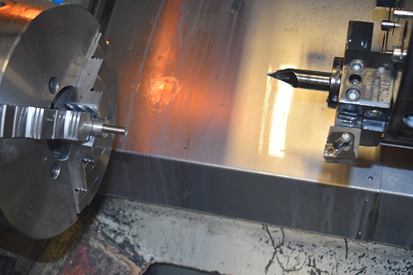
The hex was milled with a 1/2" carbide cutter, the hex 14mm. I tried to drill out the barbs in the lathe but I simply didn't have quality drills at the time, this will be a job for the manual lathe later on.
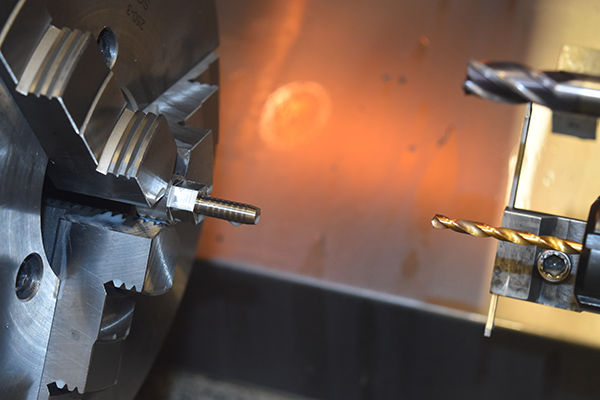
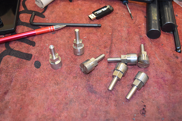
I only needed three but I chose to make quite a few spares as the manual lathe is rather useless. Some were turned to 12mm and the rest 14mm.
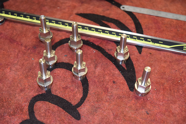
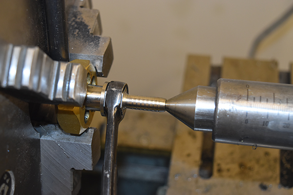
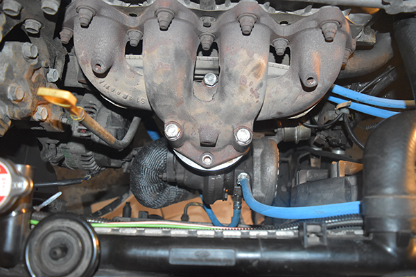
I drilled them out and then proceeded to thread them with a die. I would have personally done everything in the CNC but I couldn't get metric threading inserts in time. I used a centre to ensure the threads were parallel and had to resort to a 3ft bar on a spanner to actually turn the thing. I chose to make the oil supply for the turbo next, on the top of the head is a plug where most people choose to supply the turbo. I hammered larger tools into this plug to try and get a good grip to remove it, I failed. I searched the topic online and found that almost everyone had to use an extractor or resort to using a different source for the oil.
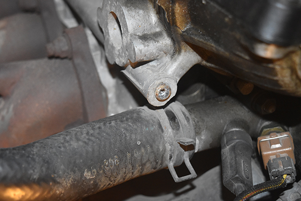
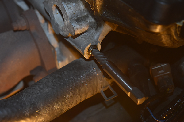
I chose to go with an extractor, it was rather easy then. The thread in the head was just the standard 1/8" NPT, for that I used a stainless barb and some thread sealant.
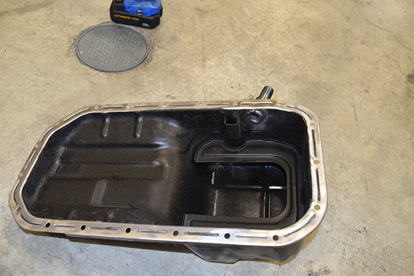
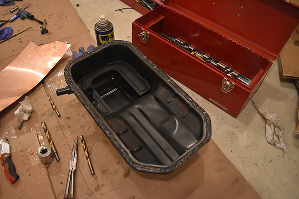
The oil pan was next, I first did my best to degrease it, I found no metal and no sludge which is a good sign.
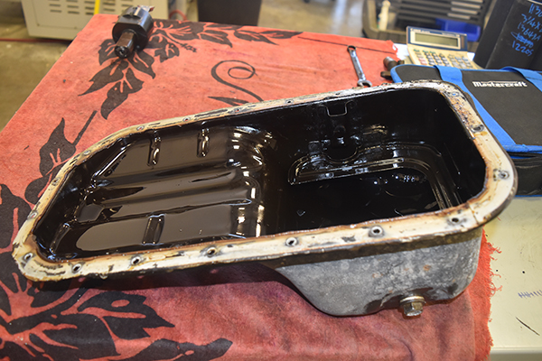
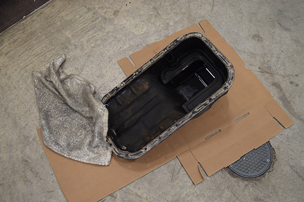
A wire brush was used to remove all of the oil sealant and all of the paint on the outside. I used a hole saw to drill a hole as close to the top of the pan as I could, in theory it shouldn't matter.

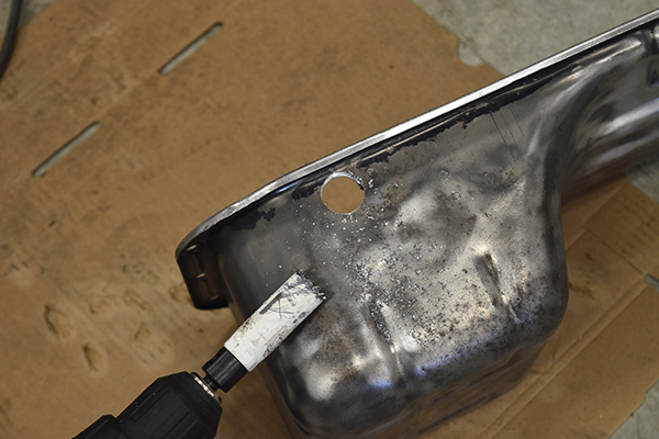
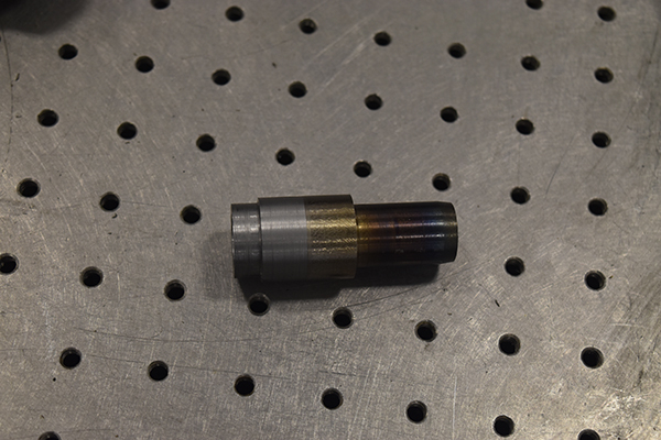
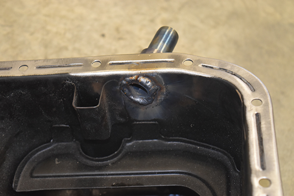
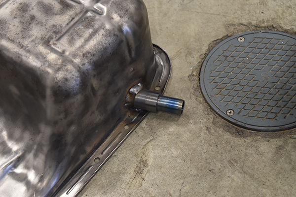
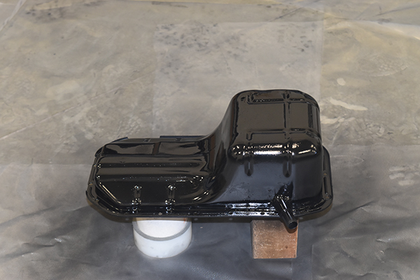
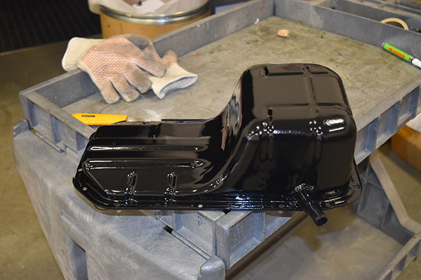
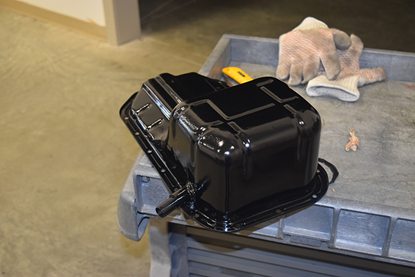
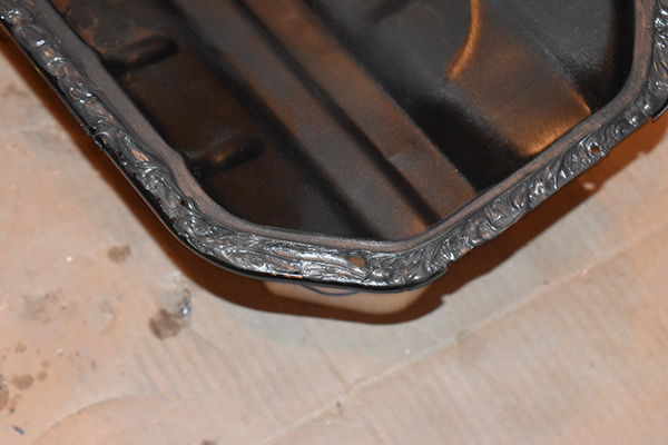
I turned a barb on the manual lathe from regular mild steel, this was welded to the pan on both the inside and outside.
Some may notice that the barb is actually pointing in the wrong direction, how I managed this without realising after I had painted it I don't know. I did cut it and point it the correct way afterwards.
It was degreased one more time and then ready for painting.

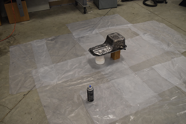
I used enamel caliper paint since it should be pretty durable.
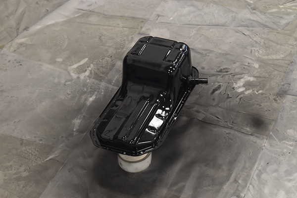
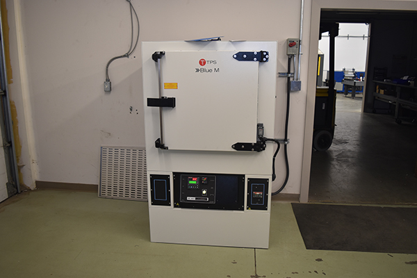
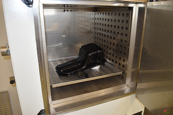
Using caliper paint meant that it had to be cured, this was done in a curing oven at work.
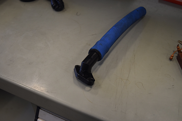
I got an oil drain for my turbo at a local tuning shop for free, I chopped it to point it in the right direction, again I had to later chop it again to get the direction perfect, this was also painted.
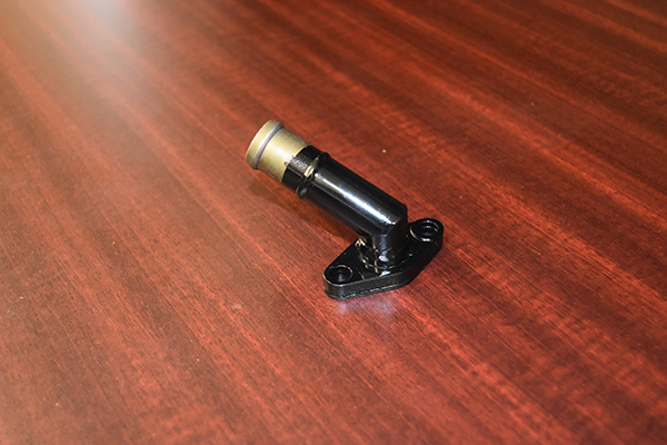
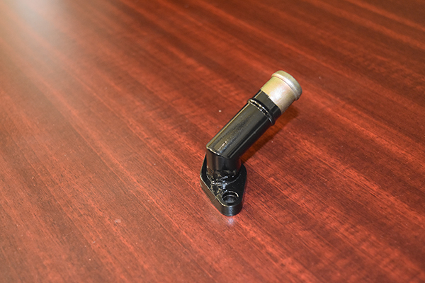
The paint is complete.
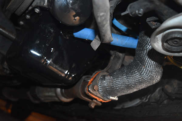
This was the moment I realised that the drain was pointing in the wrong direction and fouled against the oil filter. I took it back to work to rearrange the drain and then paint it again.
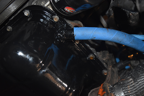
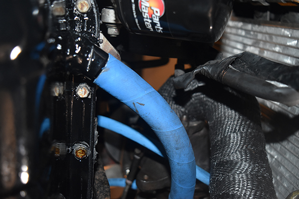
To get the hose on the drain I had to heat it to 150 deg C to get it pliable. I used high temperature Eaton Aeroquip hose for all of the coolant and oil lines, this stuff was about $9 CAD per foot. All of the connections were double crimped to reduce the risk of a failure, the coolant lines were supplied from what used to heat the throttle body.
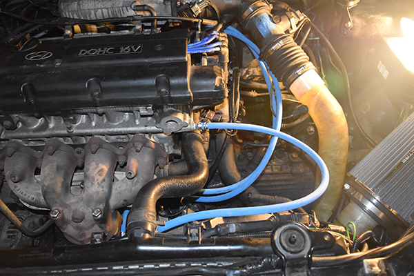
The engine is ready to start.
One of the coolant lines was close to the radiator, this will have a protector but shouldn't move a great deal when I harden my engine mounts.
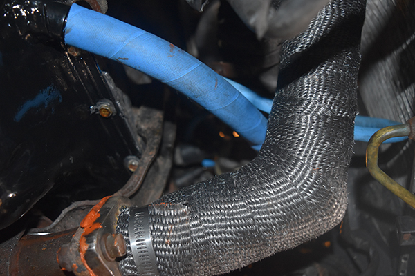
I didn't use any clamps for the drain since it would be impossible to remove without removing the bolts on the turbo side, this hose is very rigid. There should be almost no pressure in the case at low boost but when I change my pistons later with larger gaps in the sealing rings I will likely need some kind of a clamp.
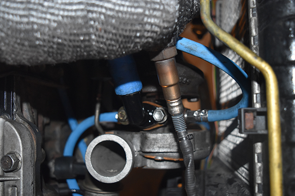
The oil side of the turbo was complete, there were no leaks and the turbo spooled up quickly. It is now just the compressor side to complete and then I have a turbo-ed car.
Hello, if you have enjoyed reading this project, have taken an interest in another or want me to progress one further then please consider donating or even sponsoring a small amount every month, for more information on why you may like to help me out then follow the sponsor link to the left. Otherwise you can donate any amount with the link below, thank you!