Hyundai Tiburon - Turbo Conversion - Fuel Piggyback Tuner
The next step in my turbo conversion is to get the second rail of fuel injectors working. For those who are new to the project I have currently converted my Hyundai Tiburon to turbo, everything is ready to go, the difference in this build is that I have two fuel rails and eight injectors. The car will run on the standard tune and injectors, the fuel tuner will read the injector duty to calculate how much extra fuel it needs to add with the second rail when the car hits boost.
Design
I have never had any experience with a piggyback fuel tuner so I can only go on what I can assume. So firstly I have replaced the original MAF sensor with an E60 off of a Nissan, the E60 is supposed to be good for around 300bhp. The first step of the tuner is to make a circuit that reads this MAF and then outputs a signal the same as stock. When the sensor reaches a certain point, that where the stock sensor would hit it's maximum, the piggyback will give out a constant output regardless of the intake flow. All of this ensures that the stock ECU and fuel system can run as though standard.
A second separate circuit then reads a MAP sensor to get an idea of the required AFR. This circuit reads the duty of the stock injectors and then works out how much additional fuel it needs to add to meet the required AFR. What I'm not entirely sure of yet is whether to use just the MAP sensor to determine the AFR and then the MAF sensor to make the calculation or just base it on the MAP alone. The thing is that if I were to run just a MAP for the whole system then I would need a temperature sensor and a volumetric table. But, since the stock MAF gets the engine to run in a specific AFR we should only need the MAP sensor for the tuner.
Example;
Engine is running 12:1 AFR at 1bar stock, the injector on time is 6ms.
If we want to keep this AFR when the turbo kicks in and reaches 1.5bar then we would assume an injector on time of 9ms.
The fuel tuner allows the stock injector to run at this 6ms, it then compensates by switching the secondary injectors on for 3ms.
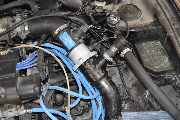
I dove straight in and spliced some wires into the original harness. Here are the wires;
CAM - I will need to know the engine RPM through this sensor.
Stock MAF - I will feed my simulated result into the stock ECU.
MAF - This is the signal from my E60 MAF.
Stock Fuel Rail Supply - I need to know if a supply cut takes place, normally when the rev limiter is hit.
Stock Injectors - I need to know how long the injectors are on for and when they fire.
Secondary Injectors - These add additional fuel.
Wideband AFR - Helps me to tune the system.
MAP - Helps to determine the desired AFR.
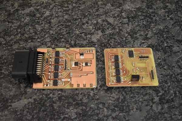
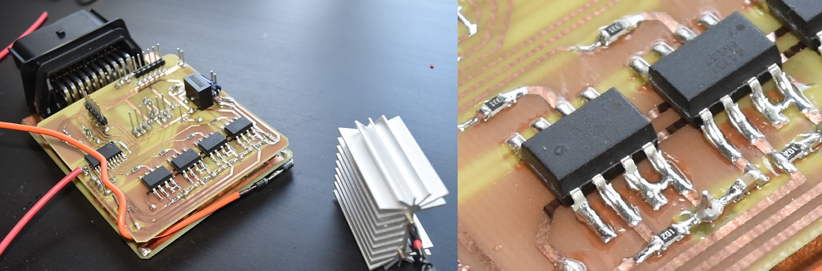
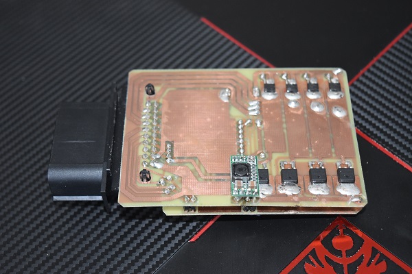
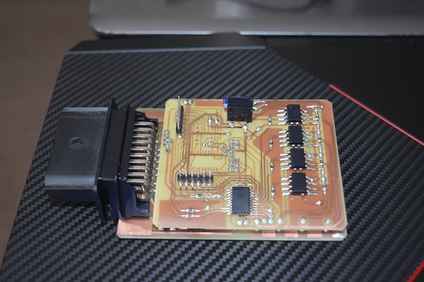
I got so carried away with the process that I forgot to take pictures of the whole process, well here is the completed board. I made a mistake on the voltage regulator which I realised after I had developed the board. I also made a mistake on a data connection port, the through holes are not linked and I have to manually solder a piece of wire in place, anyway the design would be fine if I had a board made or a could plate holes.
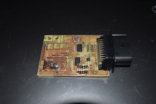
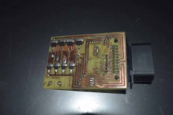
A quick explanation of the board is that it is split into two parts; the MAF simulator and the fuel controller. The only parts linking the two is a serial line in which the MAF chip tells the fuel chip what rpm the engine is running at, that's it.
MAF Side
The MAF side is there just to allow the engine to run as stock with the E60 sensor. It reads the E60 MAF and then points the value to a lookup table, the table is retrieved and sent serially to an external DAC. The DAC then goes to the stock input for the MAF sensor. At the same time a counter measures the time between each CAM pulse, this determines the engine rpm, the value is output serially.
Fuel Side
On the fuel side the chip waits for the fuel supply rail to be positive as a low input from the injectors represents on, therefore ensuring there is power first eliminates errors. The chip reads injector 1 to see how long it was on for, from the MAP sensor it can determine what condition the stock ECU is running at, say open throttle, 12:1 AFR. The chip calculates the total on time required to meet a certain AFR at a certain manifold pressure, the engine runs completely stock at negative pressure. Once there is boost the fuel controller kicks in to add more fuel.
Tuning
Well this is the hard part, especially without a data logger. The first step is to disable the fuel controller as we do not want extra fuel at this point. It is also ok for me to keep the turbo in place but I should be very careful not to run much boost, the standard injectors run out of fuel very quickly. The best method is to find datasheets for each of the sensors and compare, I couldn't find one for my stock sensor. The next best step is to connect both of the sensors in series, using a hair drier as the air source and an oscilloscope is a very accurate way of calibrating the system. The last method is to simply guess, the largest power car my sensor was ever in was about 140bhp whereas the E60 MAF was about 280bhp, that's pretty much double. So a starting point would be to double the voltages from the E60 MAF, this is all assuming the sensors are linear.
I gave it a shot but the tune was nowhere near. The strange thing is that the car would not idle properly but would rev past 2000rpm with a perfect AFR. I thought I would start with the next best method and map the E60 MAF against the stock one. I taped the stock MAF in series with the E60 MAF.
The oscilloscope was connected to the stock MAF, the E60 MAF and also the simulated output. The AFR was running perfect at idle but soon as I reached any load on the engine it ran lean. I spent another hour trying to get the MAF tuned properly but it simply wasn't linear. I have a feeling that the sensor I got was a bad one, it was from a scrap yard afterall.

I thought that since the engine ran perfectly on the stock MAF that I should revert back to that. I will keep the simulated output but when the MAF reaches a certain flow it will halt and not increase any more, this is known as a MAF clamp. The fuel side will then take over and add the additional fuel. The first thing I had to do was 3D print an adapter for the stock MAF in order for it to fit. It was printed from polycarbonate but then coated in epoxy to make it fuel safe.
Here is it printed and bonded to the stock MAF sensor via epoxy, the whole surface was covered for fuel resistance.
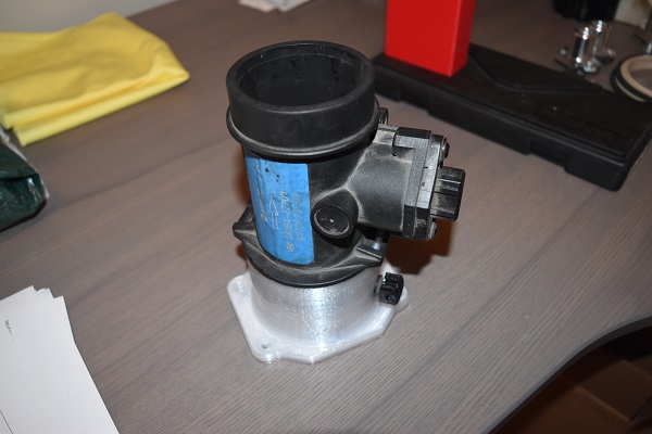
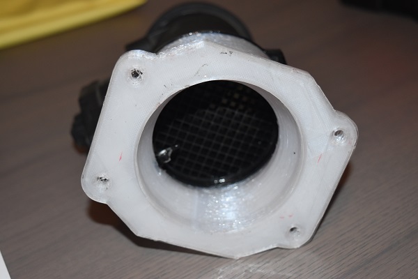
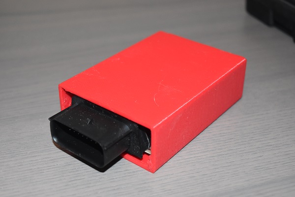
Here is it installed, I really didn't want it in white but the black nylon I had just bought would not stick to my printer bed. I also 3D printed a case for the circuit board out of PETG, this stops anything from being shorted.
I did a quick video here of the car running but it still was not perfect.
So what is actually wrong in the video. Well I only get boost for a short amount of time, it actually took me quite a while to figure out the issue. I originally thought it was due to the back -emf off the injectors that were causing a reset on the chip. I set about designing a new board which would use opto-isolators to quarantine the control circuit. I also placed a de-coupling capacitor between the supply lines to every chip. Here you can see that the board has doubled in size, I am happy to say that this board is a much better design than previous.
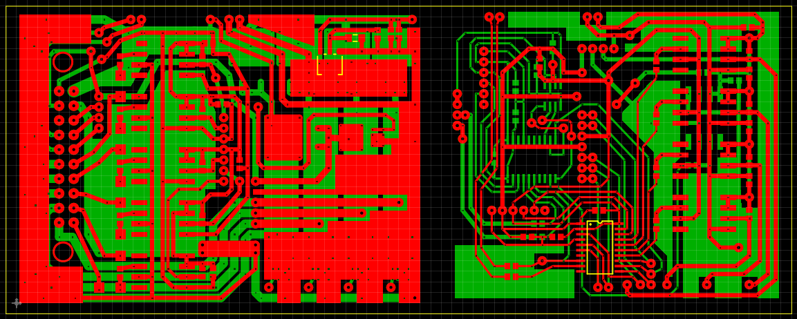
Here are the two boards, I also included a boost controller in with the design. I used a 5V linear regulator to supply power to opto-isolators and then an isolated DC-DC converter to supply the power to the microcontrollers.

So did it work, well yes and no, similar issues. I noticed that the board was getting hot right under the voltage regulator, if I held it then I would get a longer band of boost. It suddenly clicked that voltage regulator was shutting down and therefore the microcontroller. When the microcontroller is shut off on this board it causes the injectors to open causing a stall, therefore the loss in power was caused by a loss in exhaust flow.
The particular voltage regulator that I used is known as a "linear regulator" and basically works like a biased transistor. So we have a supply of around 15V dropping down to 5V, therefore a 10V drop. Say that my current is 200mA then this is a power of 2 watts that is dissipated, simply it cannot move this amount of heat and causes the regulator to shut down, a built in feature. So there are a few ways in which this problem can be solved. For one I could use a large heat sink to remove the heat but then that increases the footprint of the board. The ideal method is to use a buck regulator, these are very efficient and dissipate almost no power, they are however expensive.
So I chose to do a little experiment. I first cut the supply to the linear regulator and then used another 8V linear regulator with a couple of diodes to supply it with around 6.6V. A large heat sink was used to dissipate the heat. On a side note, look at the detail the camera picks up, these are both the same image.
So did it work, yes ! I removed the linear regulator and picked up a buck converter for ease.
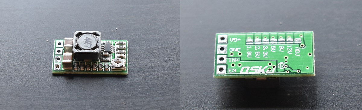
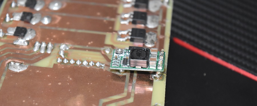
Here is the buck converter installed on my board.
The complete board.
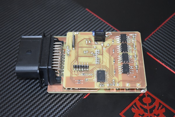
Since the board is for an automotive application it will be exposed to various environments, mainly moisture. It is not clear in these pictures but even me handling the boards has caused staining, it is the electrolytes through sweat that causes oxidation. I gave the board a very thorough wash in solvent to remove all grease and flux. I then sprayed the board in conformal acrylic which covers the whole board in a thin plastic layer.

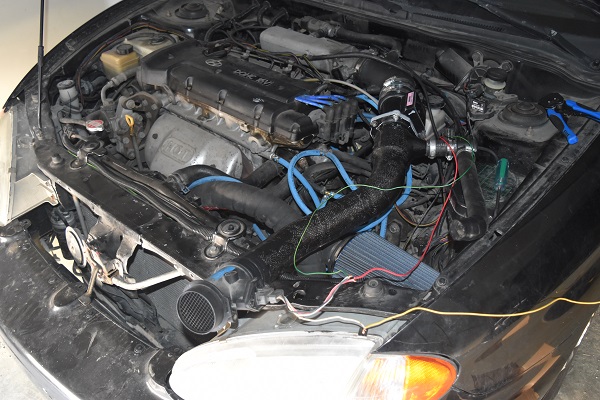
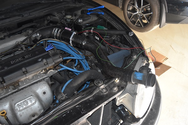
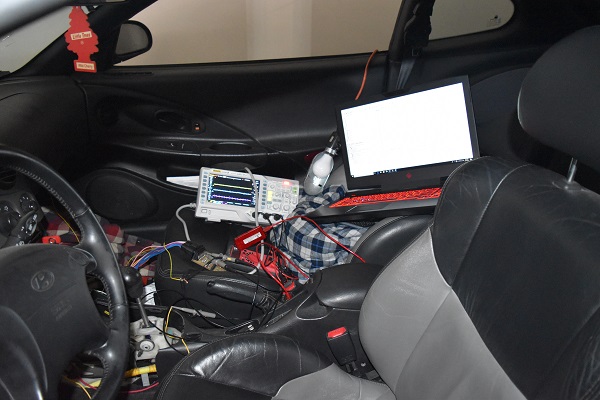
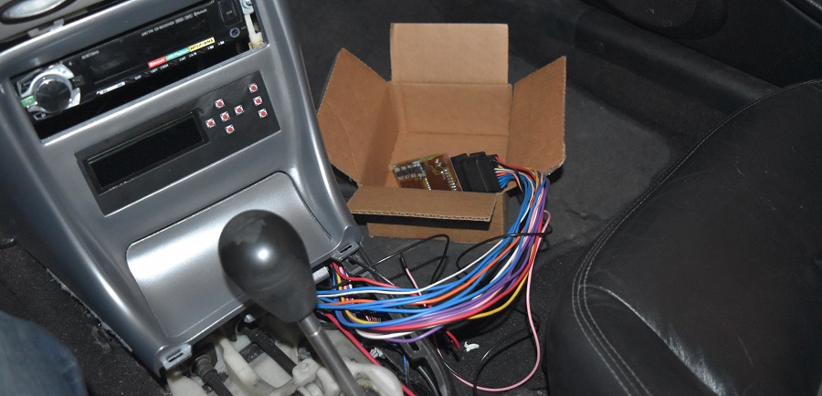
Here is how I currently have the board installed in the car, yes it certainly aint conventional. The main reason is that I must be able to access it freely while I am in the prototype stage.
Want a video, well here one is. The car is running at the stock waste gate pressure of 0.7bar / 10psi. You will see that in the video I hold off in first gear a little as to not hit the rev limiter, even though the fuel controller has been programmed to allow rev-bouncing. I used my editing software to accurately measure the time from 0 to 60 mph, I am quite shocked that I managed 6.8 seconds. I wonder what I could achieve if the car didn't keep pulling the timing. The stock ECU has been programmed to accept the worst fuel on the market, therefore it always expects the worst and cuts timing even though the fuel is the best.
I don't think I'm going to get a great deal more from this controller. Even though I have designed the board with more capabilities than what I'm using such as the boost controller, a piggyback is just a band-aid. If I'm going much further with the car then I really need to consider a standalone ECU, homemade of course. For now though I will finish off this project, so next is the design for a case.
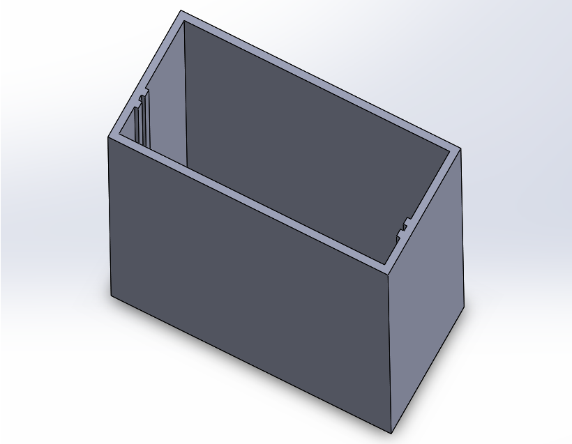
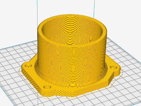
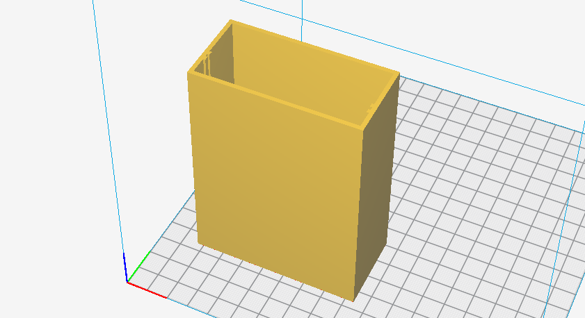
Here is the design sliced in the 3D print software.
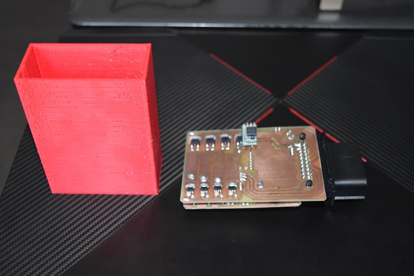
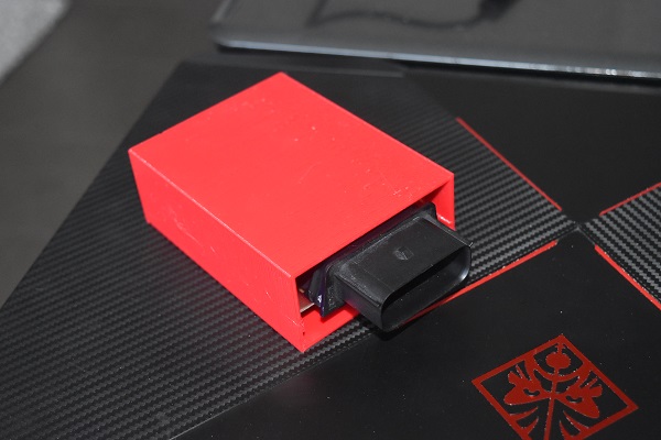
Here is the board inserted into the case, a perfect fit.
I thought I would do one last video to finish off this project. The results are quite surprising to say the least. I tuned the program slightly so that my fuel controller would kick in a lot earlier, I also waited until 2am in order for the ambient temperature to drop to 15 deg C.
Here is the full video.
This project was certainly a worthwhile effort, I see no reason why I would not use it again in a super cheap turbo build. It is unfortunately limited and I'm not getting the most out of the boost, the next step is to build a standalone ECU and totally get rid of the stock one. I have built several ECU's in the past but never quite settled on a design. Be sure to check through the projects to see what I end up building. Oh you may also have seen in the last video that if I managed to hit 2k in donations then I will do another cheap build. The car will be put to a vote. Of course I have to receive money, that at the time of writing this is currently zero.
One last update, the weather was getting really hot again so I chose to incorporate an adjustment table in the programming and hack into the IAT sensor. The car now runs a lot better and is more or less drivable.
Hello, if you have enjoyed reading this project, have taken an interest in another or want me to progress one further then please consider donating or even sponsoring a small amount every month, for more information on why you may like to help me out then follow the sponsor link to the left. Otherwise you can donate any amount with the link below, thank you!