ECU User Display Interface - Page 2
My current project car is a 1998 Hyundai Tiburon. In the near future I plan on doing some performance modifications to my car such as a turbo, in the process of doing this I will need an ECU since the stock one cannot be programmed. This project is about making a user interface that will link to other modules such as the ECU, the AFR meter, etc...
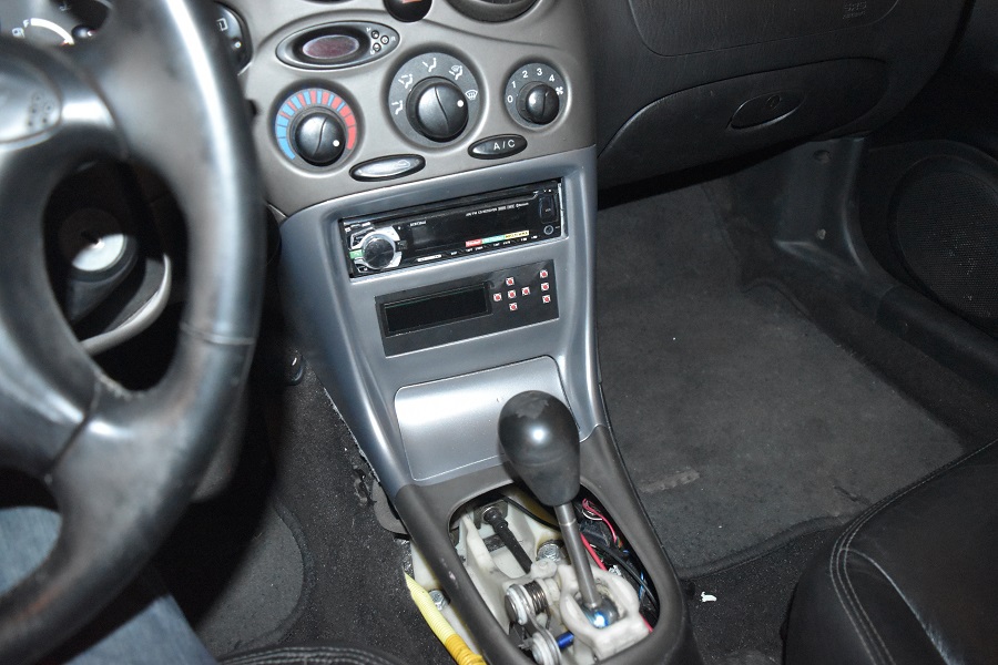
03 August 2018 - Around a year ago I made a user interface for my future ECU, as can be seen working in the pictures below.
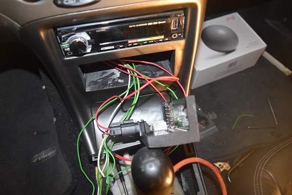
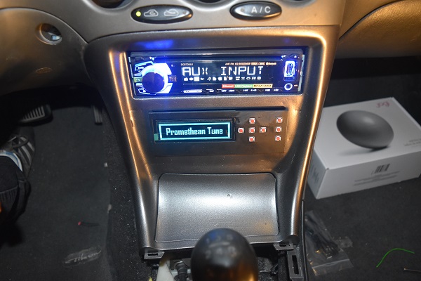
While this interface does work as in the fact that it controls the power to four auxiliary outputs, it really has little purpose. The idea was that this interface would hook up to my ECU and then allow the user to make adjustments on the go. Quite recently I have chosen to get the paintwork fixed, remember all of those horrible little dimples. Well I got all of that fixed with the aid of some filler, it now looks how it should. I took a piece of plastic and matched it to the lid of the paint can, well you can see how that turned out. It's functional for now, I just don't need to spend any more money.
So does this project still have a use? Well it was over a year ago that I wrote the program for the module, I hope that I still have it too. The original problem was that it was a massive pain in the arse when it came to programming the EEPROM. The fact is that I have used a lot of EEPROM or flash in many of my projects before and have always had trouble programming it. I have started building a module that will accept an SD card and transfer the data into flash or EEPROM chips.
I have also been having a lot of issue settling on a design for an ECU, particularly because I either don't like my original design or I find a better one. I made a standalone ECU for my car with some advanced peripherals on the board, it was quite expensive because I chose to use automotive connectors. The fact was that sometimes a spike in the supply would cause a chip to reset or cause noise in the rest of the circuit, this led me to design my own on-board isolated power supply.
I believe that the final design that I have come up with is hopefully going to be a working one. I have chosen to go with a modular ECU so that I can get each part of the system perfected and that they can also run independently of each other. Running several separate cores is a lot easier in terms of programming than fitting it all onto one core, it also speeds up everything and makes the system more accurate. There will be a master control module, this simply reads data from input modules and then sends the data out on a bus so that the output modules can interpret the data. The idea with this system is that the main control module can remain the same while different input or output modules can be added to compensate for future upgrades.
So what does it mean for this project. Well I believe it still does have some use in that the user will be able to see what the engine is doing and what things are reading. It will need an intermediate board in order to convey the signals as each module will be isolated, this reduces grounding loops and noise. I will also try to tie another project in with this page as I will have another user interface, this one will be portable and have a much larger screen.
Hello, if you have enjoyed reading this project, have taken an interest in another or want me to progress one further then please consider donating or even sponsoring a small amount every month, for more information on why you may like to help me out then follow the sponsor link to the left. Otherwise you can donate any amount with the link below, thank you!