1998 Hyundai Tiburon - Dual Injector Modification
At the current time of writing this (Oct 2017) my Tiburon is my daily driver but also my modification platform. In the near future I plan to develop my own ECU system mainly so that I can cheaply modify cars in the future. There are however certain precautions I must take so that if my ECU was to fail then I would be able to plug back in the stock one to still be able to drive home.
I am nearing the stage where I will be adding a turbo to my car which means that the fuel injector capacity must be increased, this of course means that my car would be unable to run on the stock ECU. To combat this problem I will opt to go for dual fuel injectors meaning that doubling them up will allow up to 300bhp with the stock injectors, they are also very cheap to pull from a scrap yard. If for some reason my ECU fails the primary injectors will still run the engine with the stock ECU, I would have to ensure the boost is cut if this problem arises.
I have seen this modification on quite a few different builds, it is the standard setup on a motorcycle to have two injectors per cylinder. This modification is actually more beneficial than running larger injectors since it will give better fuel control, large injectors often cause idling and starting issues because they can't deal with low pulse widths. There is also no reason why one set cannot be standard and the other set be larger. The main issue with this build is that most ECU's are not designed to run like this, the work around is usually the standard injectors run sequential for the low end and then the secondary injectors are bunched together to run the high end power, this means only five (or six depending on current capability) outputs need to be used, often ECU's are limited to six sequential injectors.
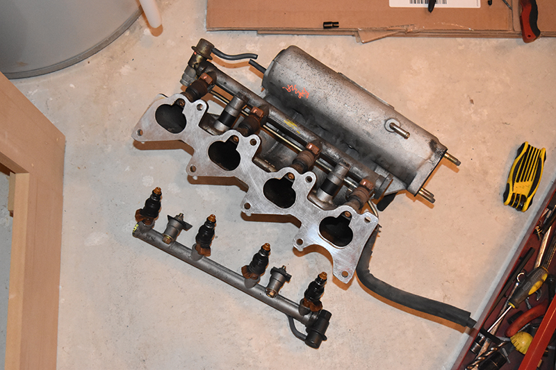
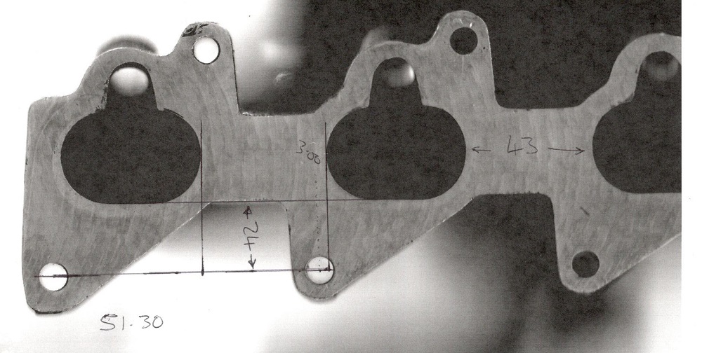
29 October 2017 - The first step was to find a manifold, I could measure the one on my car but that was a hassle. I went to a local scrap yard and got an inlet manifold, two lots of fuel rails and two lots of standard injectors for $40 CAD.
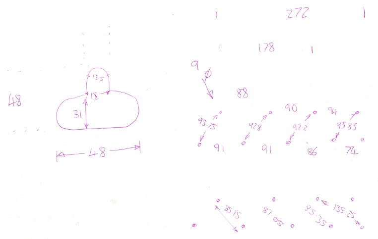
I took some rough dimensions and placed them on paper.
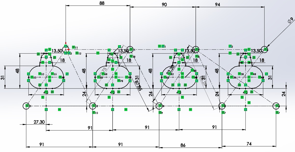
I then proceeded to measure the hole spacings again and drew up a CAD, it is not always easy as these are castings and were never made to tight tolerances. Since it is a metric car and the designers like round numbers it meant that it was a little easier to predict what the actual design values were, for example 81.8mm would likely be 82mm in the design.
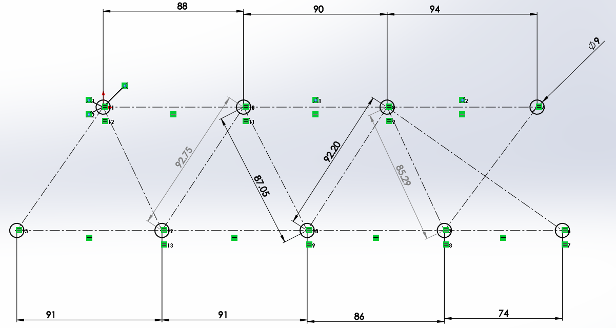
Once I had the hole spacings it was time to add the holes for the fuel / air passage, again this was a little guesswork.
I scanned the manifold and printed it so that I could get some measurements on the positions of the passage ways.
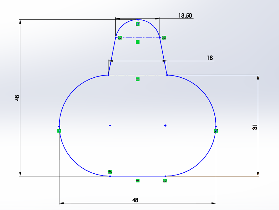
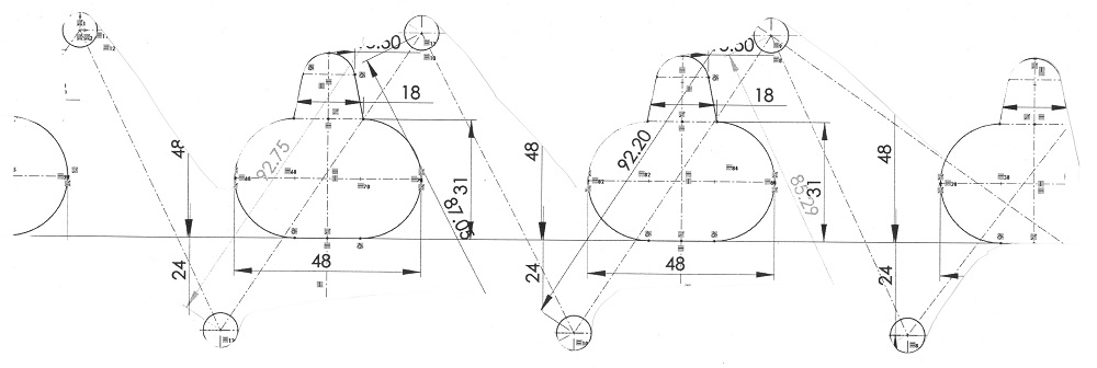
Once I had all of this information I updated the drawing, so far everything looks good.
Before I went any further I chose to print the above design to scale, I cut it out and laid it over the manifold to see if all of the edges matched, they did.
I then did some more measuring on the inlet manifold with the injectors to get a feel of how things should go, again most of this is guesswork. I mostly guessed the angles since I was going to prototype the design first. In the end I worked out a design that looked feasible, I took into account that this mod would push the inlet manifold towards the firewall. There would still be plenty of room, I think, if the engine did somehow manage to twist that much I think I would invest in some heavy duty engine mounts which I may have to do in the future if I choose to go crazy power, bearing in mind it is a FWD car so any more than about 300 bhp would be pretty stupid.
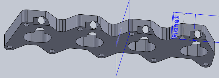
I split the part in half in the CAD software and then saved them as two separate parts, I then proceeded to 3D print both of them.
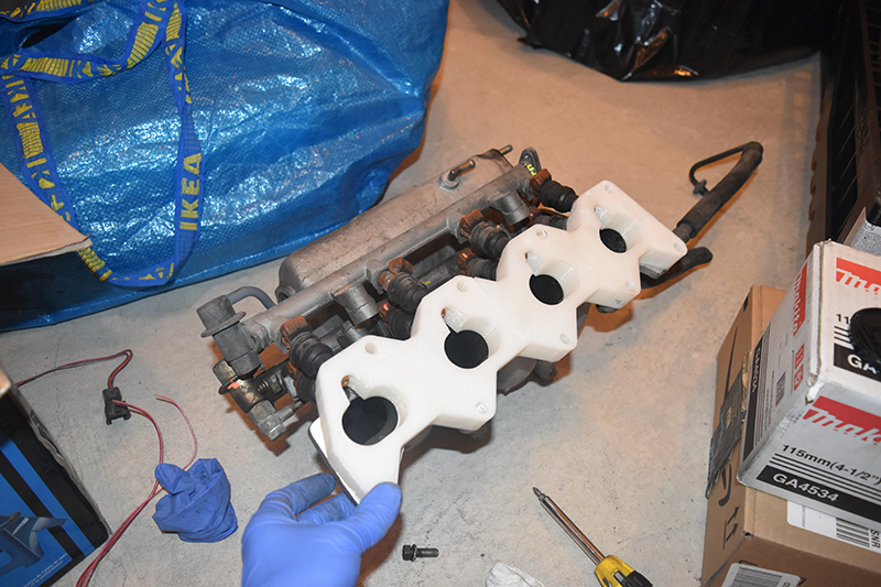
I placed the injectors into these spacers to see if everything cleared as it should, all of the holes aligned perfectly. I had to make a slight modification to the depth of the injectors but overall it looked pretty good.
Now the difficult part, how do I make it. I don't have access to a decent miller but I do have access to one so I could machine it myself, the issue is the cost of tooling. I decided to ask for a quote from many different machine shops, I guess I will see what the prices are and then go from there.
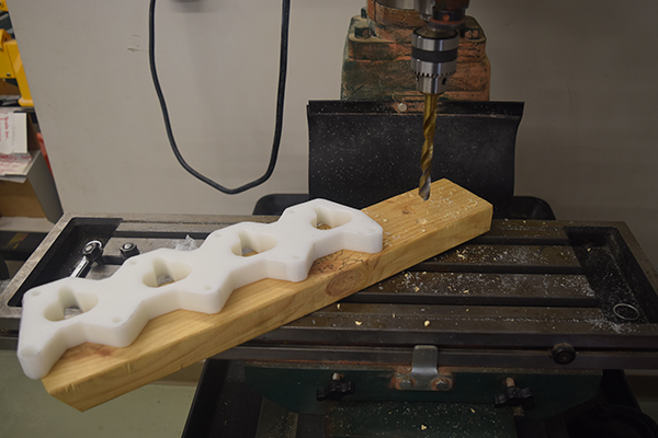
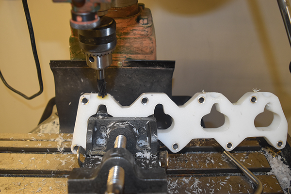
17 February 2018 - I got just a single quote out of a total of ten and the price was unreasonable. I asked the machine shop next to where I work to do it back in November but they never got back, I recently asked again and supplied them with some material. I only need them to water jet cut the profile and then I can finish off milling the holes myself to save on cost. In the mean time I bought some pieces of HDPE which should be good for engine temperatures, the only issue I can see is the thermal expansion and that they may expand more than the sealant. I cut out the profile on a scroll saw and then used the 3D printed part as a template to drill the holes, I then drilled the holes bigger in the mill so that I could press bushes in place to stop me from squashing the plate.
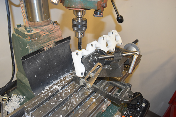
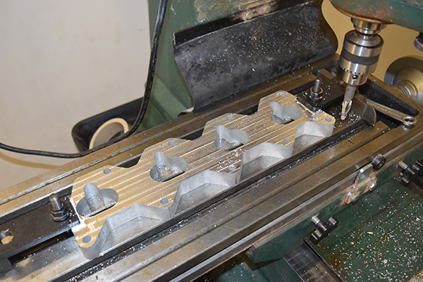
I quickly set up a program in the CNC lathe to make some bushes, I then pressed them into the plate. Next was to mill and drill the holes for the injectors to sit, I used a tilting vice set at 30 degrees, not ideal but it worked.

The process was rather archaic but I got there in the end, not all that accurate either as I eyed most of it.
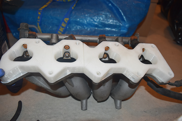
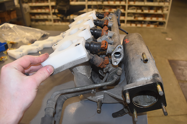
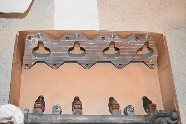
The plate lines up and the fuel rail fits.
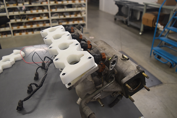
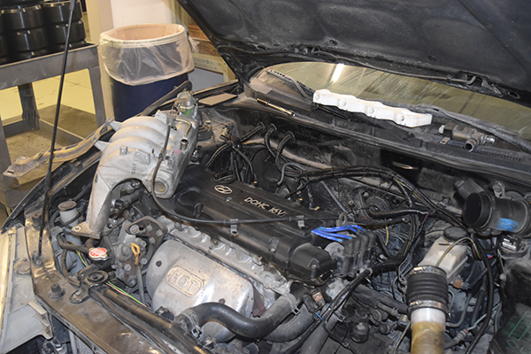
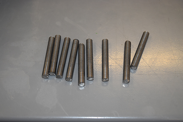
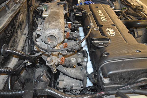
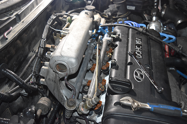
The next step was to remove my intake, remove the existing studs and then replace them with longer ones. I couldn't find anywhere local that supplied studs so I had to go with threaded bar instead, I did the installation in such a way that I would not screw the studs into the head too far, I also used thread lock.
I ran some sealant around both sides of the plate, installed it and everything seemed to fit just fine. I'm hoping that the plate I'm having cut won't take too long so this doesn't have to remain in my car. I can see two issues, due to thermal expansion of the plastic it may cause the sealant to weaken, and two, the plastic may become soft and leak around where the injectors seal.
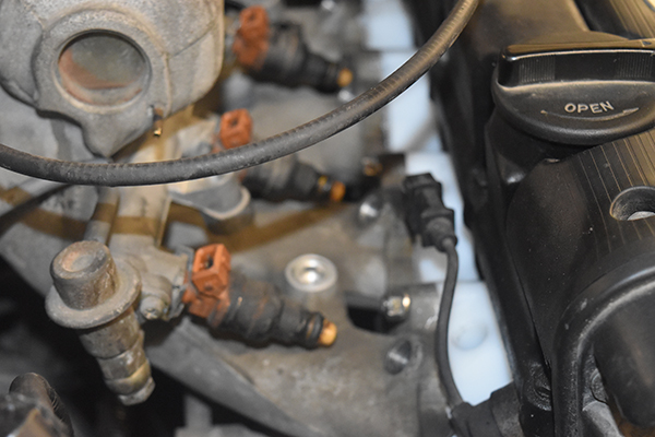
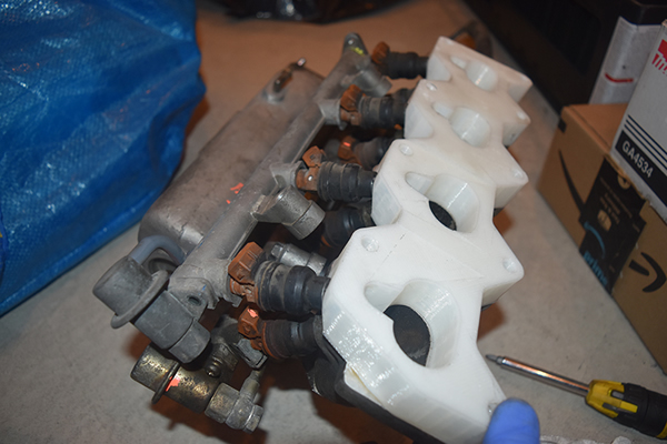
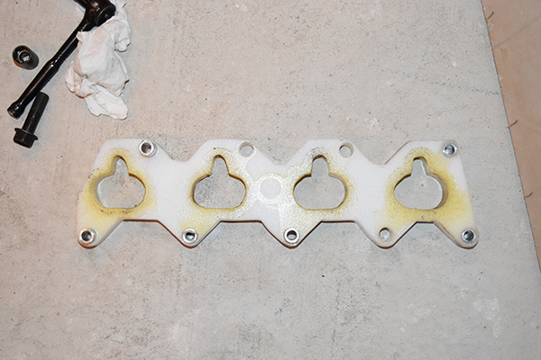
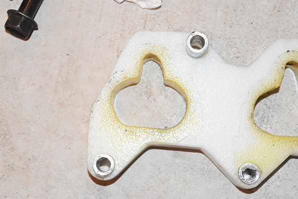
22 March 2018 - It has been well over a month and the plate has still not been cut, I'll get onto them again because I need it urgently now. Over the past couple of days I have noticed that my AFR's have been a little erratic along with the idle, this is clear indication of an air leak. I checked the injectors to find injector 1B be wet, it is leaking. I chose to remove the intake that night and remove the spacer, I returned the car back to standard for now. Here below shows the spacer, clearly my fears were met and the injector did leak as well as the sealant began to fail due to expansion.
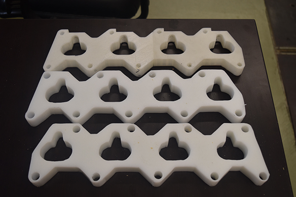
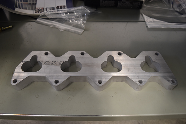
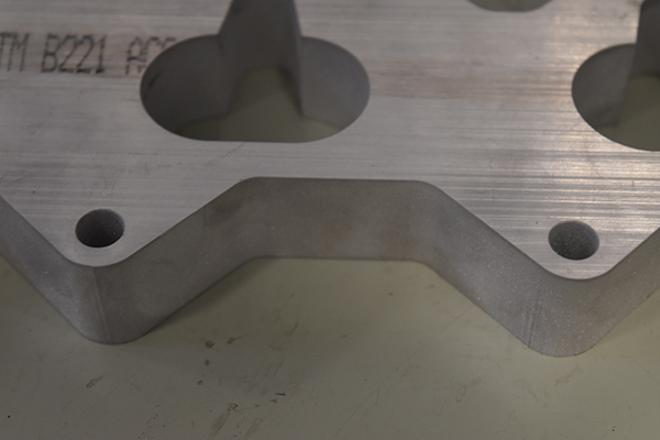
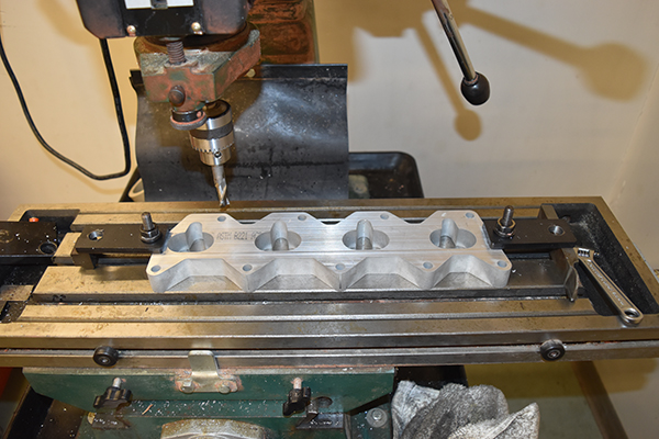
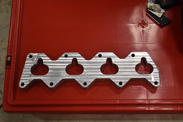
11 April 2018 - Finally they managed to fit it in to waterjet cutting, the result is great, much better than I would expect from such a process.
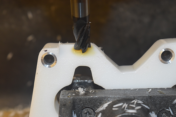
The next step was to skim the part to the right height, I was given the permission to use the miller at the shop next door. The issue was that I only had the time in my lunch, instead I chose to stay behind after work to get the job done on the monkey miller.
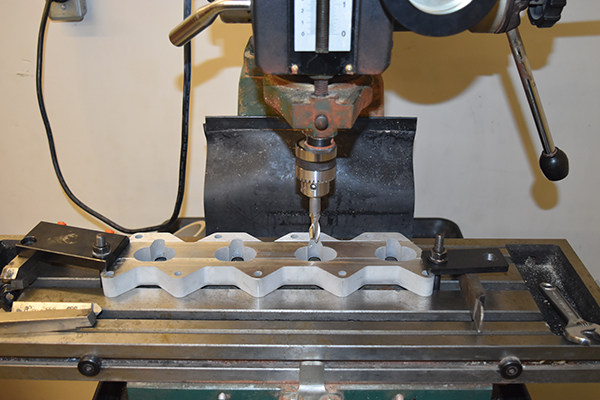
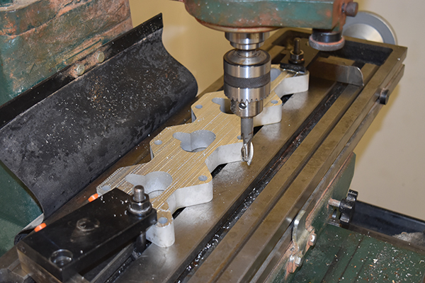
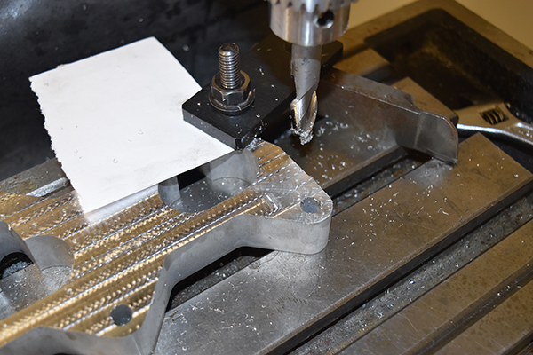
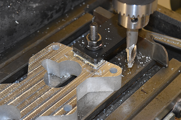
It took a while to get there, I also used a tilting vice to complete the injector holes. I was quite amazed to find the part varied no more than 0.02mm in thickness, I guess a cheap miller can be fairly accurate.
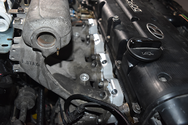
The spacer installed.
Check out the rest of the projects to see how the turbo conversion pans out.
Hello, if you have enjoyed reading this project, have taken an interest in another or want me to progress one further then please consider donating or even sponsoring a small amount every month, for more information on why you may like to help me out then follow the sponsor link to the left. Otherwise you can donate any amount with the link below, thank you!