Hyundai Tiburon - Turbo Conversion - Exhaust Side
At the current time of writing this (March 2018) my Tiburon is my daily driver but also my modification platform. In the near future I plan to develop my own ECU system mainly so that I can cheaply modify cars as part of a side project. The main idea of modifying these cars is to turbo them for cheap while making them reliable, the only way to do this is to make the parts myself. This project is the first stage in converting my Hyundai Tiburon to turbo, this will concentrate on the exhaust side.
The turbo came from a Saab, not sure which one, probably a 9-5. I do know they are good to around 18psi and capable of around 300bhp which is far enough for this build since I will be keeping the stock pistons. Anyway for a turbo setup you can do the exhaust side for around $500 CAD if you have your own turbo and get a cheap Chinese manifold and down pipe, these are prone to cracking and not recommended. I chose to do it all myself and utilise the machines I have access to, I will also add that I could have done all of this with a grinder, welded and drill press.
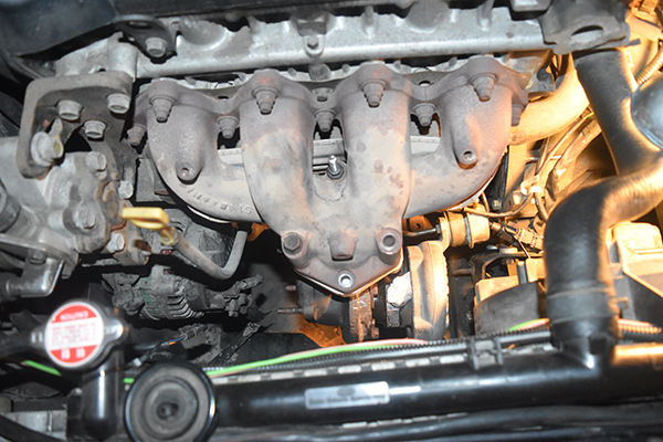
So the idea is to keep with the stock exhaust manifold because it's cast iron, durable and pretty cheap to replace if I have to. It means that I must make some kind of an adapter for between the manifold and turbo. The first method would be to draw out the flanges and have them water jet cut, then to weld a tube in the middle, this option is what I would do if I didn't have access to a machine. The option I will opt for is to machine this adapter from a solid piece of steel. The down pipe would also be made from steel tube, the bends would be made in sections to cut cost.
The Design
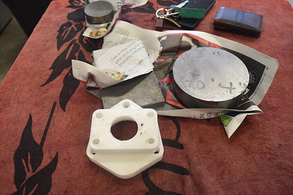
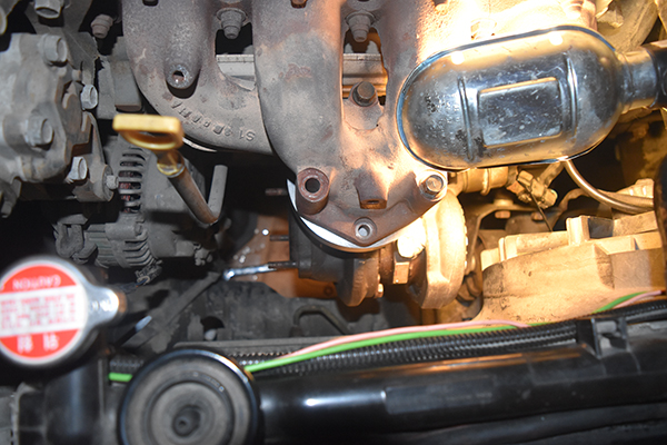
The first step was to make a design for the adapter, I first started out with making a rough sketch of both the engine manifold and the turbo flange. I then turned it into a 3D part to be printed in plastic with a 3D printer, this would ensure everything aligns. The first part required a bolt hole to be adjusted slightly, secondly there was not enough clearance between the down pipe and the alternator. I altered the design and 3D printed another part.
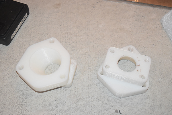
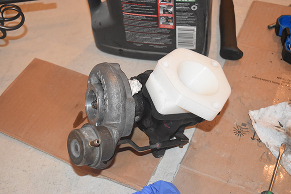
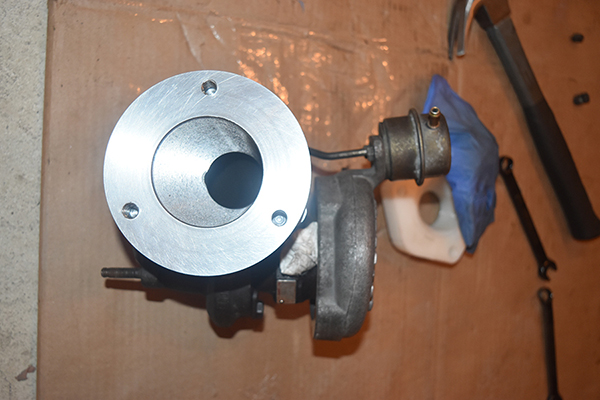
I used the part to install the turbo to make sure that everything fit, which it did.
Machining
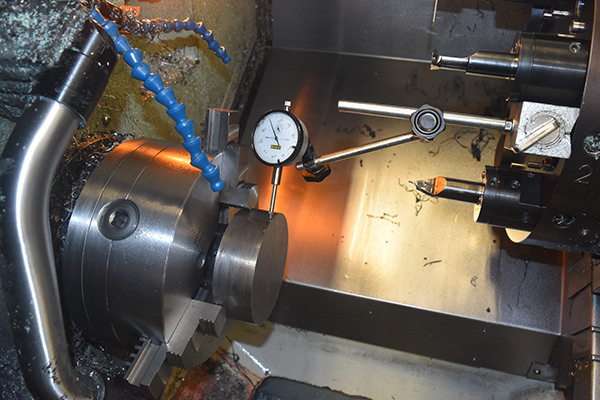
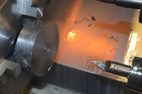
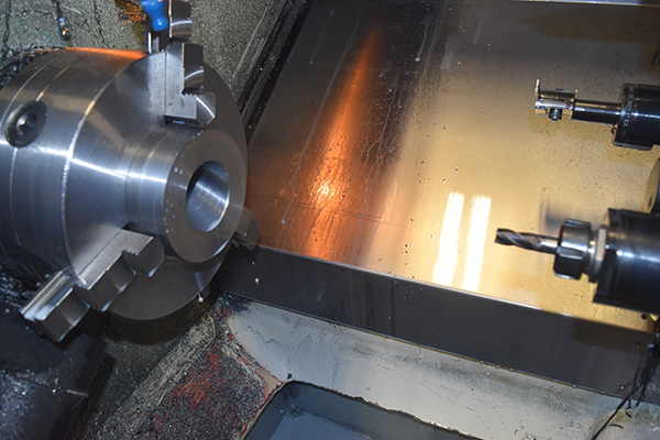
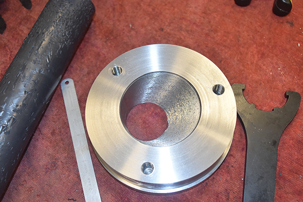
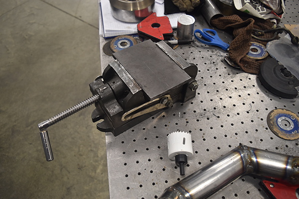
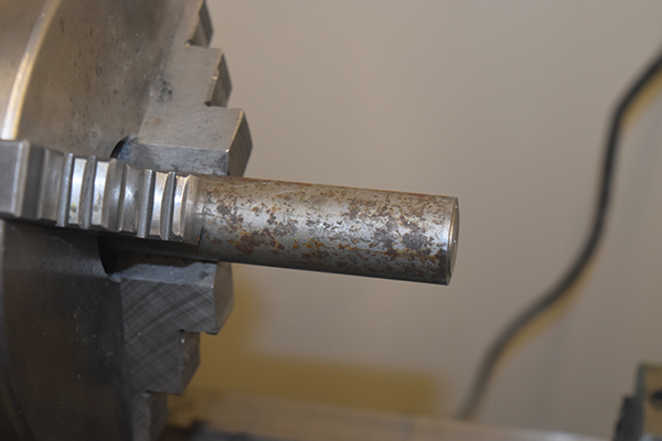
I was pretty happy with the way the turbo sat, the clearance between the alternator was still a little close but there's little I can do without making a new manifold. I picked up an offcut of 3" steel to make a flange for the down pipe, a piece of 3/8" for a flange for the down pipe and a piece of 5" steel for the adapter. The steel for the adapter was supposed to be mild steel, it was however bright in appearance which lead me to believe it was actually carbon steel, turned out it was. I first started by making sure the 5" section was true in the lathe.
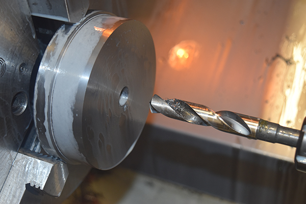
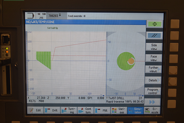
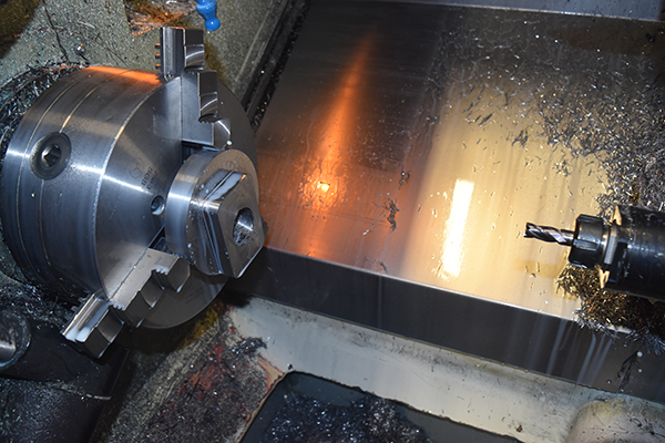
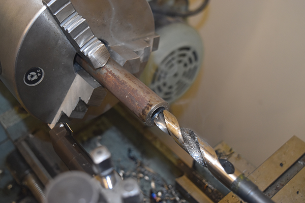
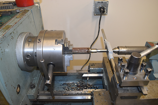
The bar was faced, the outside turned and a drill through the centre since I planned to use an end mill and these are not designed to be plunge cut without a pilot hole.
The first time I tried to mill this part I found out that my HSS cutter was no good and the steel was not mild but in fact carbon steel. I picked up a coated carbide end mill which had no issues at all. I programmed it all manually to rough out the part and then finish cut, the milling operation took around an hour.
The holes for the studs were drilled and then tapped manually, I personally don't like machine tapping but it was an option.
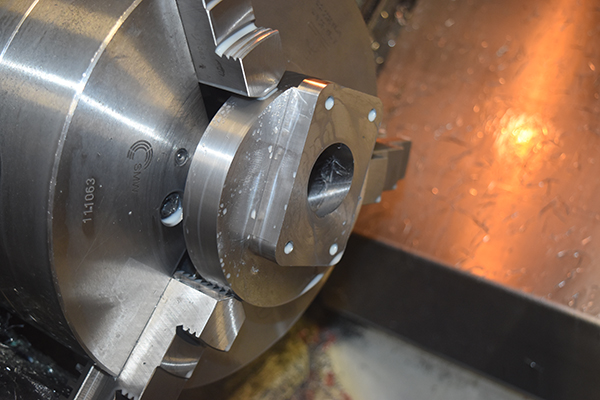
I flipped the part to mill the flange for the turbo side. I first faced it off and then run a milling program to cut the square part, the program was not very efficient since I programmed it manually but for a one off it didn't matter, it took around 45 minutes total.
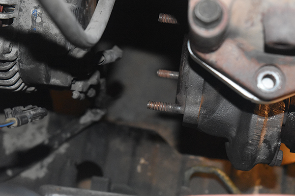
The holes for the studs were drilled and tapped. I used the studs that I removed from the intake and used these for the turbo. Normally the studs are in the turbo itself, these were removed (with great difficulty), then drilled out.
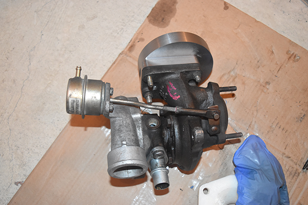
The turbo fits !
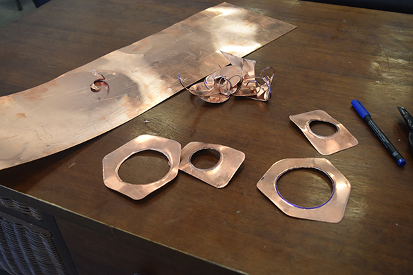
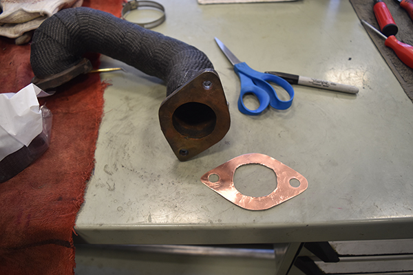
I read quite a lot into gaskets and what I should use. Some said not to use one at all, some say grease, some sealant, some custom steel gaskets, some aluminium sheet and some copper sheet. I could see quite a few problems with each of these, I chose to go for copper because I've seen this used a lot in the past.
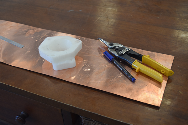
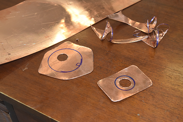
The issue with using copper to begin with is that it is too hard, many say to use thermal treatments but there is a simple way around it. If the gasket is installed as it should be then the heat through operation will soften the metal, it will leak for the first few runs and seal thereafter. I also installed the barbs for the oil and coolant as you will see in a separate project.

Down Pipe
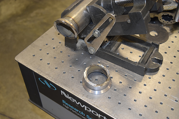
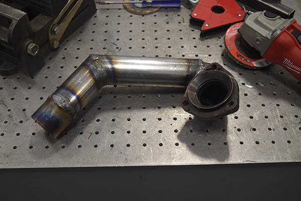
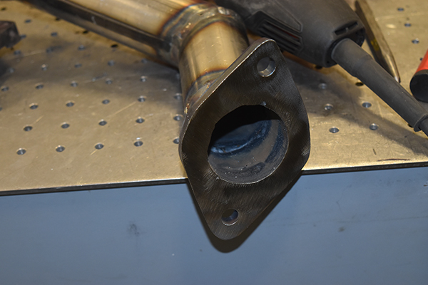
This is another part that has to be custom made for my application, it is also the most difficult part to make while not having the car next to the fabrication equipment, I had to make a few journeys in between to get it right. When I retrieved the turbo I made sure to get the original flange, luckily it was at a 45 degree and nothing difficult to make. The 3" offcut that I picked up was machined into a flange and then bored out for my 2" exhaust pipe to fit, it was welded on the inside and machined again to flatten the welds, the outside was also welded.
The down pipe required a rather steep bend due to the clearance with the alternator, I had to do it the old fashioned way with cutting segments and welding it together.
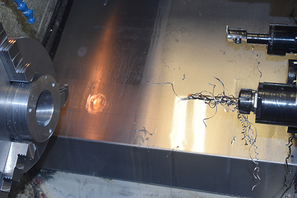
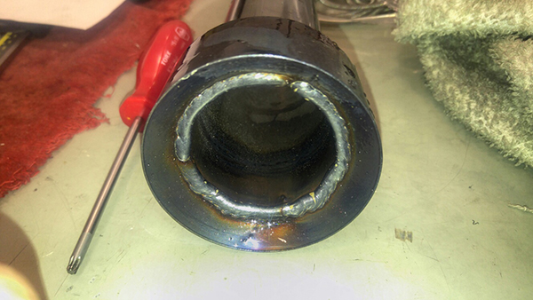
The welds started out great.
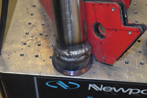
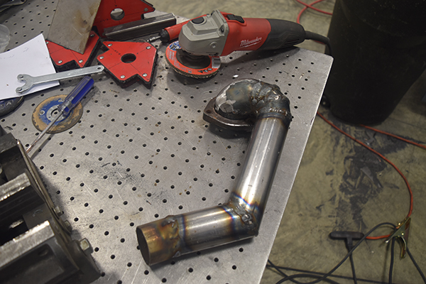
I tried to clean up the welds with the grinder because I hit a contaminated spot, I had to grind back the weld a few times, hence the mess in the right picture, thankfully the inside had no blobs. The exhaust cleared the alternator with about 20mm to spare.
This whole next part was mostly guessing from dimensions I had eyed up.
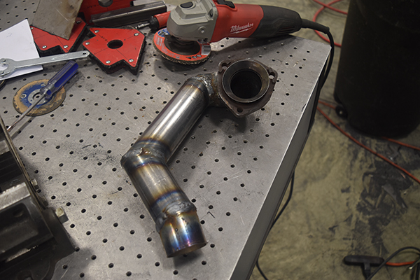
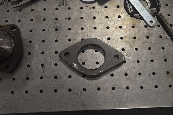
The pipe looked to be good so I started on the flange that will connect to the rest of the car, this is where I imagined I would have the most issues. I started with drilling out a 2" hole in a piece of 3/8" steel plate.
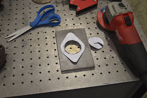
I made a template with a piece of paper and then cut out the flange with the angle grinder.
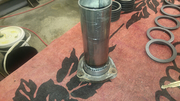
The flange was welded on both the inside and outside.
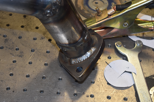
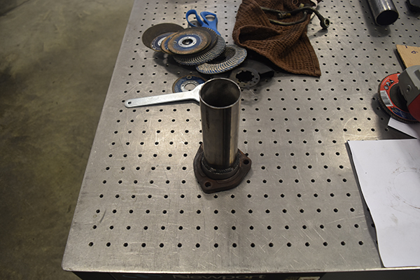
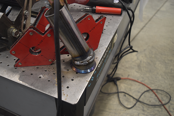
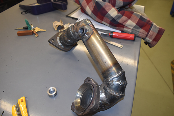
The down pipe is starting to look complete.
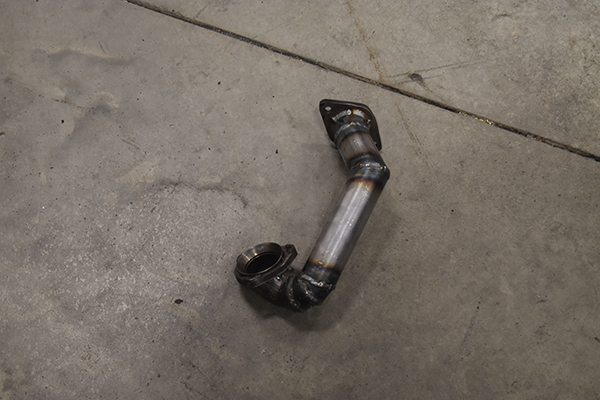
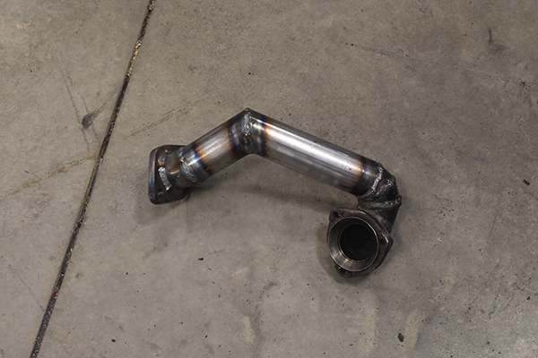
I took it home and it didn't fit, as to be expected. It actually took me three attempts to get it right, hence all of the welds.
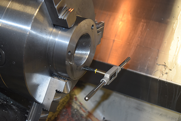
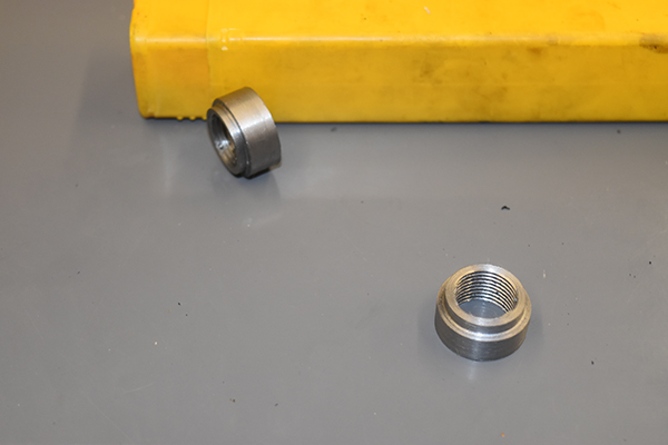
The bung for the oxygen sensor was next to make, I used some 1" carbon steel I got for free. I drilled it out and then bored it to 16.5mm for the tap.
I was going to make this bung in the CNC just because using a threading bar produces better results and it's easier. I also wanted to make quite a lot of these for future use but I could not get a metric threading insert at short notice so I had to go for a tap, a rather expensive one at that, $60 CAD, it was M18 x 1.5 which is an unusual size. I thought I would make at least two just incase I decide to make my own oxygen sensor controller to compare with my current one, another project in it's own.
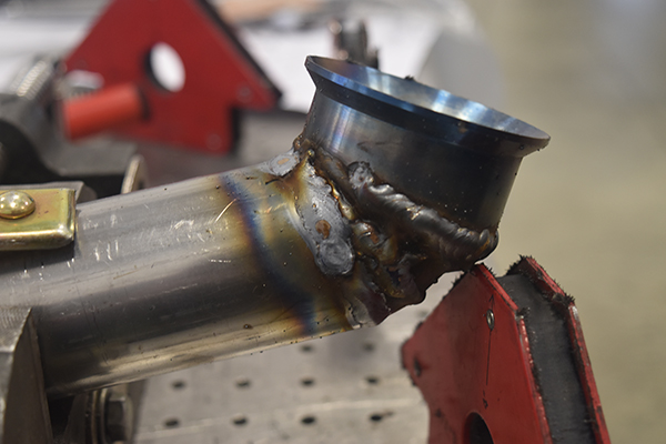
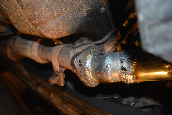
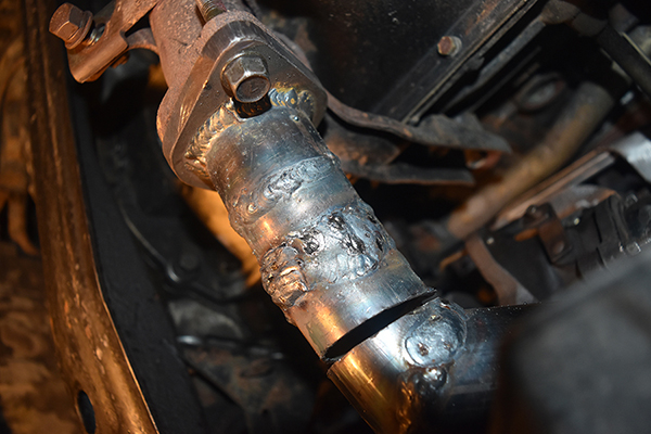
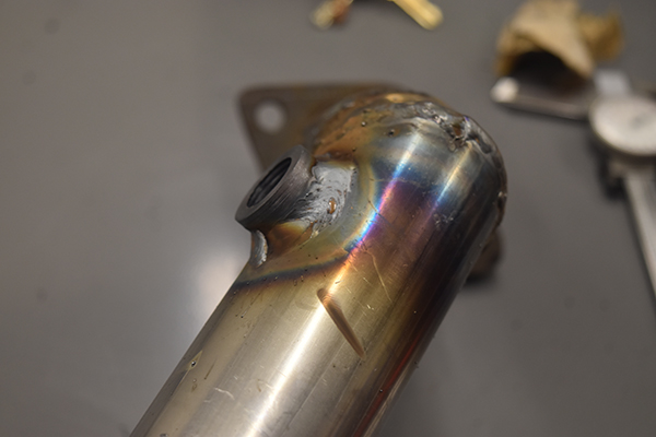
The hole for the bung was drilled and then welded in place, the welds came out great. The other welds came out ok but I went a little crazy with removing contaminants, something I haven't encountered often, it must have been oil soaked in the steel. If I had a TIG then I would have cleaned all the welds, however over kill since I will be wrapping this part.
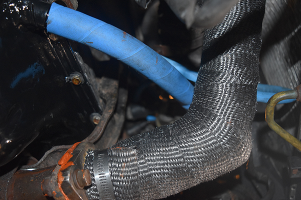
I had to wrap the down pipe due to it's close proximity to the alternator, it also covered up the welds, or how many times it took me to get it aligned. I doubled wrapped the tube and used a stainless clamp to hold where I started and finished (the same place).
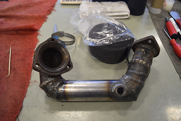
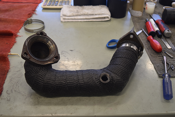
I assumed the flange would not be flat since it originated from plate and the fact that I welded it. Even though I used a copper gasket I also chose to use a high temperature sealant especially for exhausts.
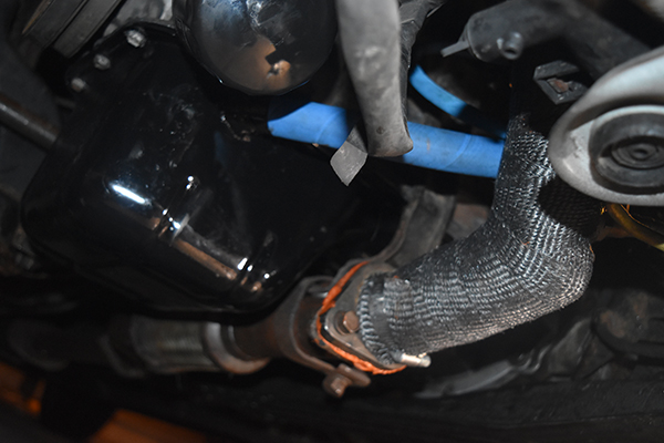
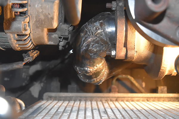
Here you can see the exhaust side of the turbo is now complete, the oil lines are covered in a separate project.
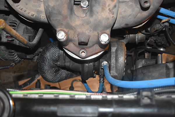
I forgot to mention that I rebuilt the turbo to make sure all was good, I think that the turbo was pretty new because there was absolutely no slack at all in the bearings and the condition was excellent. I took the car for a test drive, it was certainly a lot slower due to the turbo restriction which led me to remove the waste gate. Check out the rest of the projects to see how this project pans out.
Hello, if you have enjoyed reading this project, have taken an interest in another or want me to progress one further then please consider donating or even sponsoring a small amount every month, for more information on why you may like to help me out then follow the sponsor link to the left. Otherwise you can donate any amount with the link below, thank you!