Compression Moulding Machine Ventilation Hoods
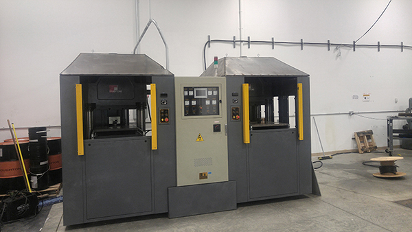
As of January 2018 where I work acquired a compression moulding machine, twin platen with a clamping force of 250 tonnes each. After running the machine a couple of times on a tame material such a nitrile we found that fumes were nauseous, this would become more apparent on materials such as Viton which can release caustic and sour gases, not ideal on a daily basis. I chose to contact a local air conditioning and ventilation business to receive an estimate of $6 - 7k CAD and then possibly an additional air make up system if the ventilation requires more than 1000 cfm of air flow out of the building.
The machine is about 4 metres wide by 2 metres depth and 3 metres tall. I did some quick sums to realise that if I were to buy a welder, sheet metal and some fans that I would come to around $3500 CAD and then of course we would be left with a welder for future use. After some persuasion we agreed that we needed a ventilation system and that to make it ourselves would be the most cost effective solution. I consider myself to be pretty decent at design and fabrication so was excited for the challenge.
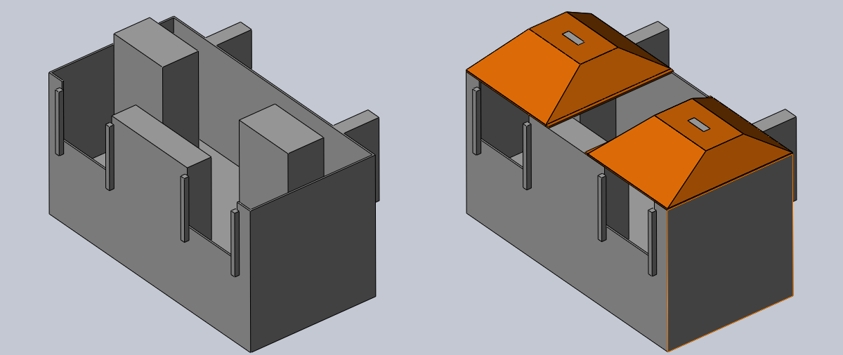
I made some rough measurements of the machine and turned them into a CAD representation of the machine, I could then design a hood to fit over it and ensure there was clearance between all parts. The hydraulic press part of the machine protrudes about 35cm above the rest of the machine, this part also needs access since the daylight has to be adjusted to accommodate certain moulds, something that would be almost impossible with a hood being present. The idea was that the hood would be relatively light weight so that around 4 people or a small fork lift could be used to lift them with ease incase of the need to adjust for a larger mould. The hood would rest on the top of the machine with a few lugs to locate it in place, the hood would also have to be made into two parts since there is an electrical conduit situated towards the middle of the machine.
Design
The first step in the design was a CAD representation of the machine, the second step was to make a CAD of a hood for just one side. I then created an assembly to see how both of the parts would fit together, ensuring there was clearance. I then mirrored the hood to create two sides since the machine is symmetrical. I chose not to include the electrical conduit as this is something that I will do by eye when it comes to the fabrication. Here are a few pictures of the design.
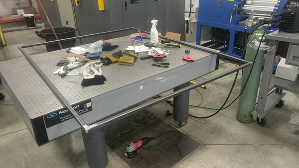
Material, Tools and Construction
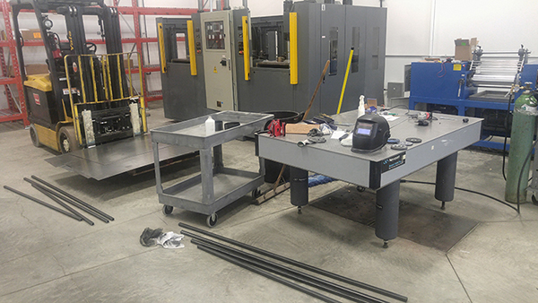
I chose to export each of the panels for the hood into a dxf format so that they could be water jet cut, I quickly abandoned this idea and chose to go for full sheets that I would cut myself manually with an angle grinder. I wasn't quite sure how accurate the cutting service would be so I chose to round the numbers up to the nearest inch, even though I worked in metric everything had to be cut in inches even though Canada is supposed to be metric !?. I had a total of eleven sheets cut, five each for the hoods and additional sheet that will be placed in the middle to hold them together. A few lengths of box section and a few sections of tube that will connect to the ducting system.
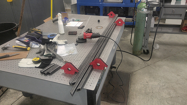
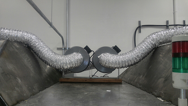
I then went on a shopping spree to buy an angle grinder, magnets, welder, gas, etc... In total all of the materials, tools and fans for the system came to around $3500 CAD which is almost half the price of the quote that I received earlier. With the combination of the two fans will bring the airflow to the limit of 1000cfm, if I required any more flow then it would probably be sensible to make some sliding doors at the front of the machine to limit the total amount of daylight present and therefore increase air flow.
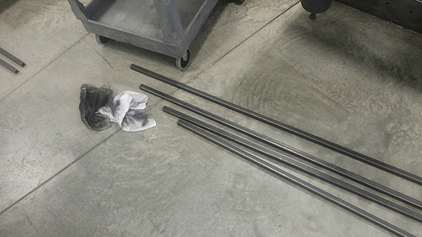
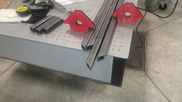
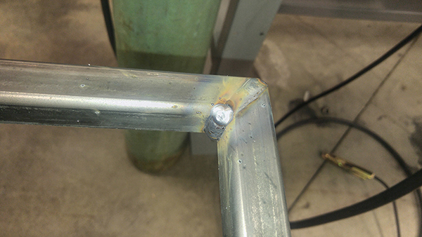
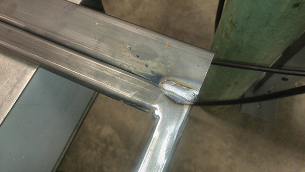
The first step was to remove the packing grease from the box section since this will be harder to remove later when I prep for painting. I then cut the sections to length for the frame, I eyed them at 45 degrees to get a nicer edge, of course I cut them slightly oversize.
The edges were then ground to a 45 deg angle, again using eye and a protractor. The process would have been a lot easier with a chop saw but then again I was on a budget, the process took a little longer.
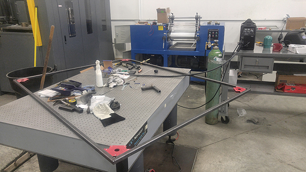
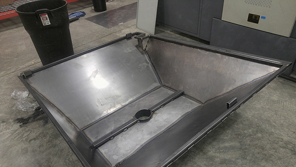
I used some corner magnets to get everything aligned and square before tack welding the frame together. I measured diagonally to each corner to ensure the distance were the same and therefore the frame square. I then proceeded to weld all of the corners and then grind the welds flat that will sit on the top of the machine, I want it to sit level.
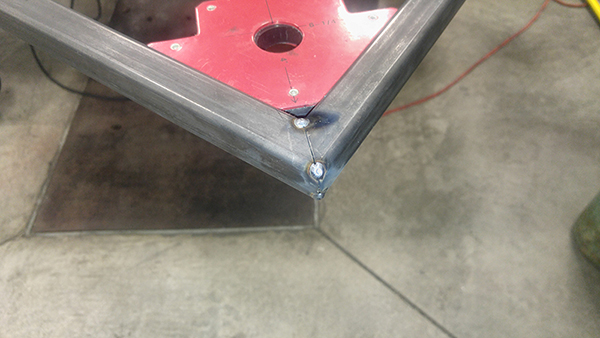
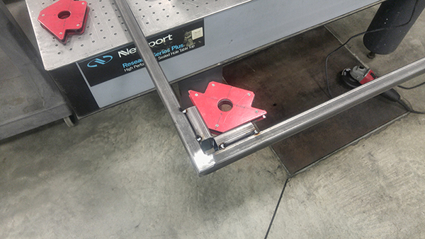
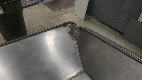
A total of six lugs were cut and welded to the frame, these allow the frame to sit on the top of the machine but not slide around. Using this kind of system means that the whole assembly can be removed quickly but also will not have any possibility of falling off.
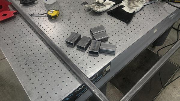
A piece of rectangle section was welded to the side of the frame, this is where a sheet will bolt holding both of the hoods together.
These are a few more pictures of the lugs that will centralise the frame to the machine.
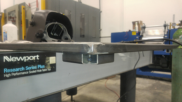
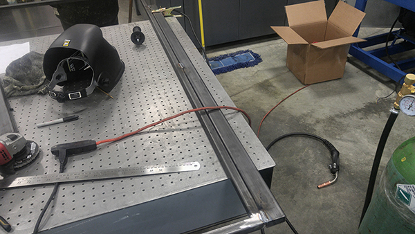
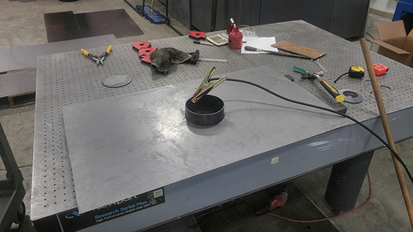
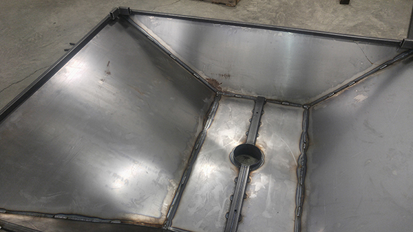
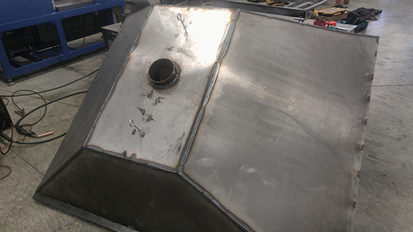
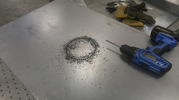
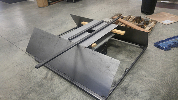
The lugs then solidly welded in place, a tack would suffice since these bear no load. Next was the sheet that will situate in the middle of the hood and allow the gasses to vent. I first traced around a tube, punched some marks and then drilled a series of holes, this is the old fashioned way of doing things.
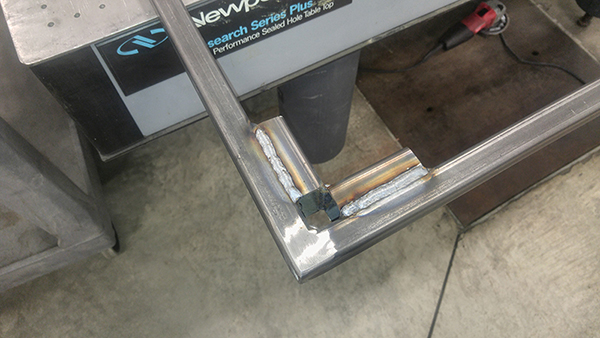
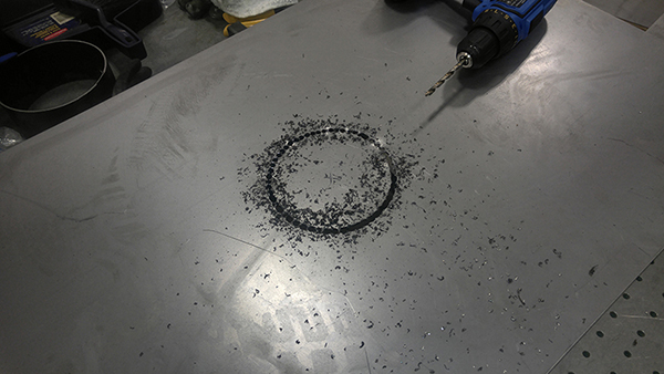
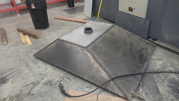
The hole was punched out and then grinded to allow a tube to slip in, the ventilation ducts will fit to this tube. I made a fatal error in welding this tube in place, I did weld in patches to avoid distortion but the sheet greatly warped. A support bar was welded down the middle of the sheet, this adds some strength for the lifting hoops I will add later. I had some issues with my CAD software so from here on I chose to eye most of it, measurements were still made to ensure things were square.
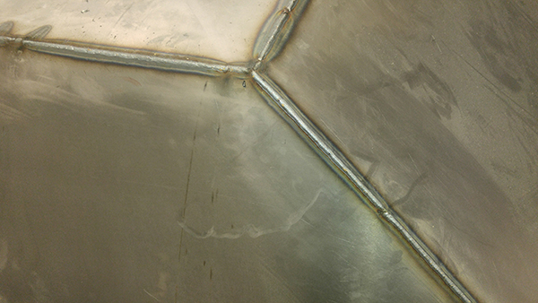
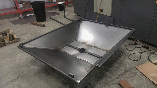
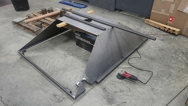
I got a little carried away with welding and grinding but here you can see the result. I first tack welded the side panels to the frame and the top sheet. I used a ruler and then the angle grinder to cut these side sheets. The front and back sheets were then tack welded in place, I did the exact same and cut off the excess with the angle grinder. I finished off with completely welding together all of the seams, I used a series of smaller welds around the bottom of the frame to save time, gas and filler.
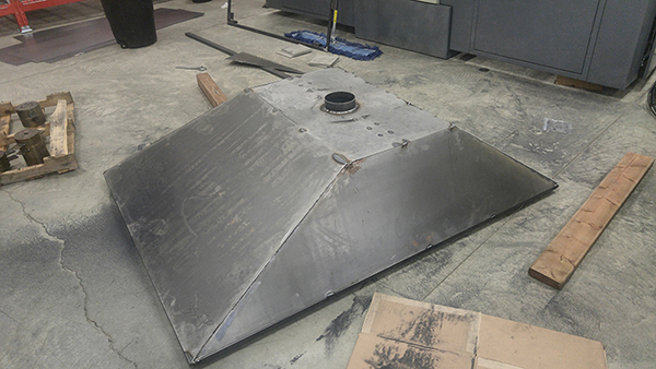
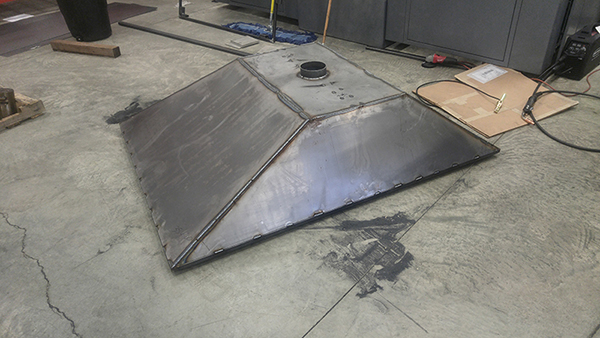
I flipped the hood to weld some of the inside to add some strength since the outside will be later ground down for cosmetic reasons. This hood used 2mm sheet and 3mm walled section, this thing is certainly a lot sturdier than what a ventilation business would have supplied.
Here are some more shots of the hood, take note the position of the locating lugs.
I drilled some holes and installed some lifting eyes / hoops.
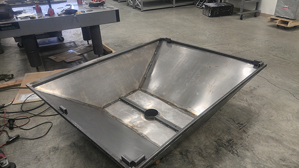
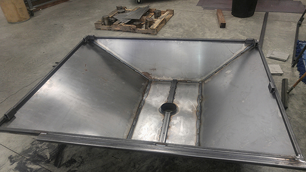
The second hood was a little easier to build since I learnt my mistakes and how I could do things better. This time I did not weld the tube in place, I did weld a support bar in place to aid in fabrication, basically to keep the top sheet from flexing.
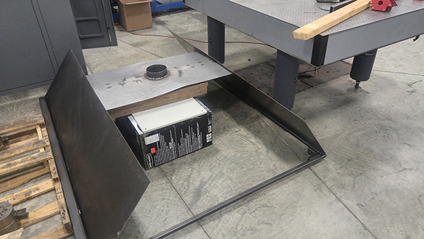
This time I remembered to take some pictures on the fabrication process, note that in the bottom of the left picture I modified the frame to accommodate the electrical conduit supplying the machine
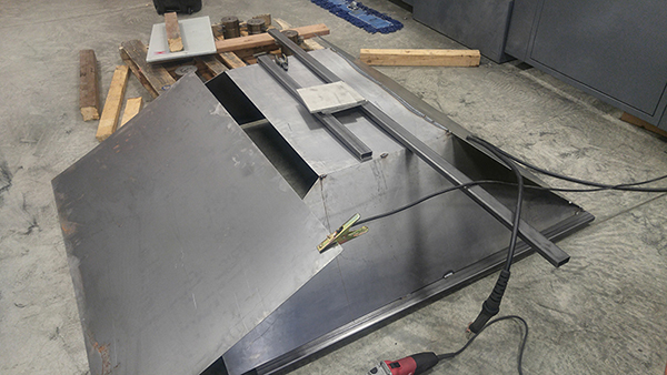
The welding was a lot easier since I had no warping to deal with.
The support bar was welded in place down the middle of the top sheet.
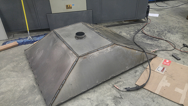
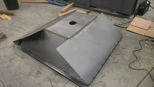
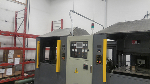
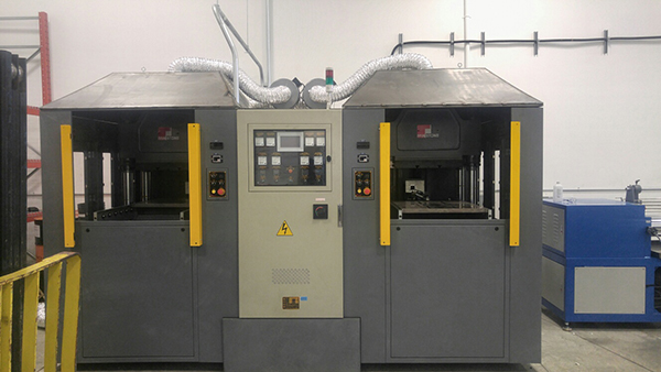
I quickly cut of some pieces of sheet for the conduit pass. The hoods were lifted in place with a forklift, thankfully they were easy to locate and fit perfectly.
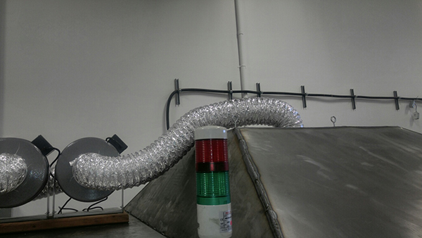
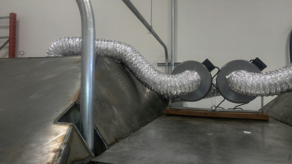
The sheet and ventilation were added a week later.
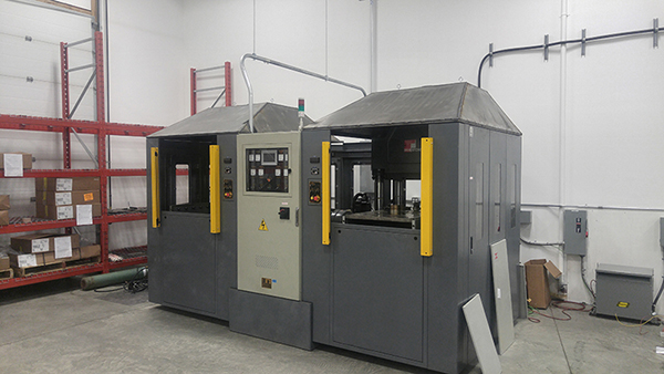
The project was done on a rush basis but the result was satisfying as I did not cut any corners. My only issue is that because we were in a rush I did not get to clean the welds and paint the hoods, well maybe I get to later in the year. Overall the fabrication took a total of two and a half days, not bad considering I had to manually cut everything with a 4" angle grinder. One last note: So glad I had moulded ear plugs because this was a very noisy project. The hoods worked perfectly too, ideally I needed a little more airflow but this time there was no smog in the room. Just a little elbow grease and thought saved my company 3k CAD and of course a lot of time, this would have likely taken weeks otherwise, something we did not have.
Hello, if you have enjoyed reading this project, have taken an interest in another or want me to progress one further then please consider donating or even sponsoring a small amount every month, for more information on why you may like to help me out then follow the sponsor link to the left. Otherwise you can donate any amount with the link below, thank you!