Wide-band AFR Meter
The first step to real tuning is the addition of a wide-band lambda / oxygen sensor. Most cars will come equipped with a zirconium type of sensor that can only read a ratio of between 13 to 16:1, in fact it is more like 14 to 15:1 since the accuracy is not all that great. The wide-band sensor is normally referred to in the automotive and tuning industry as the UEGO sensor (Universal Exhaust Gas Oxygen). The excellent attribute with this sensor is that it can measure an AFR of between 10 to 20:1 which is the only range you will ever need for tuning.
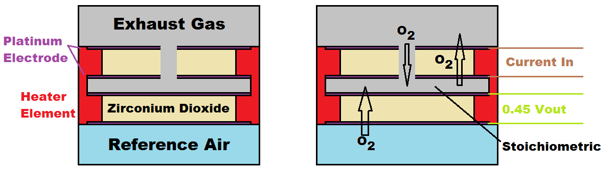
So how does this sensor work?
Going back to the narrowband zirconium sensor that worked by oxygen passing through the platinum elements producing a voltage, a voltage of 0.45V indicating a perfect stoichiometric ratio. The difference with the wideband is that it has two narrowband sensors, except one has a small pin-hole allowing oxygen to bypass. As current is passed into the exhaust side element in pulls oxygen back into the exhaust stream. We have a control circuit that adjust the current in order to keep the reference air sensor at 0.45V, the amount of current we need to pull the centre of the main sensor to stoichiometry is our AFR.
The narrowband was simple because it only required power to the heating element, a sensor ground and then a single output telling us lean, stoichiometric or rich. The difference with the wide-band is it's much more complicated control circuit which allows us to get a much more accurate AFR reading. For this project I will not be building a controller as that will be for later, I will instead be creating a meter to run an existing lambda controller I have bought. Since I have no way of calibrating a sensor controller the only way to ensure that the one I build is accurate is to compare a known accurate controller from a manufacturer.
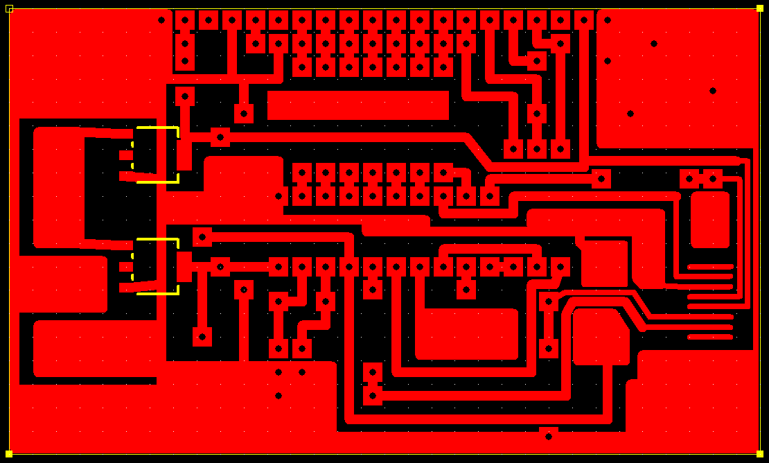
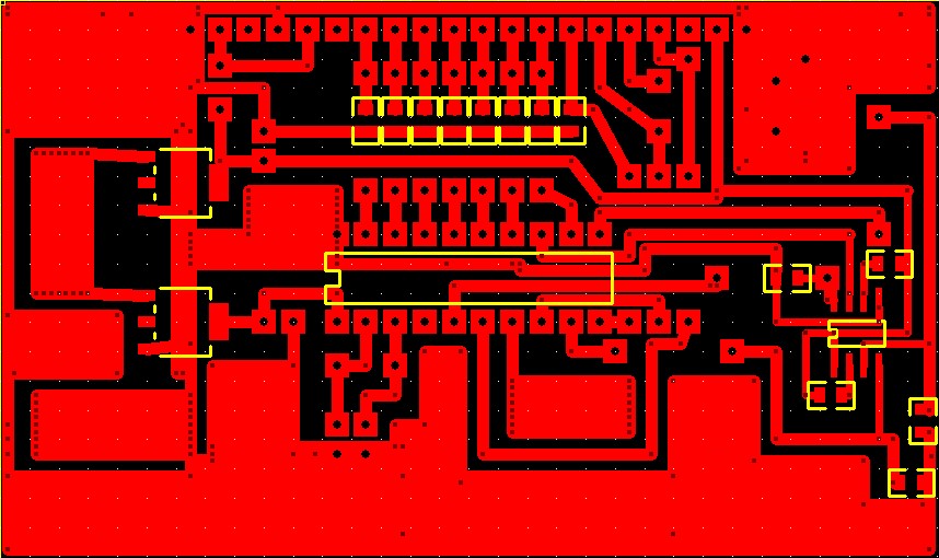
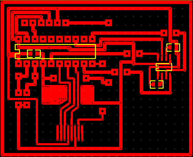
I'm not going to publish a circuit diagram as I don't use one myself, microcontrollers are simple enough to follow. The difference with my display compared a lot of commercially available ones is that mine uses an OLED display allowing custom characters to be shown. I have chosen an SD card to hold the data for if I want to change the font, if I do however decide to sell these then I will likely save the data to a FRAM chip instead of the SD. Below is the board layout.
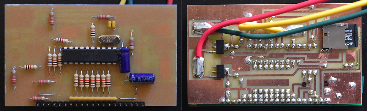
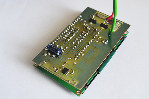
Here is the board completed.
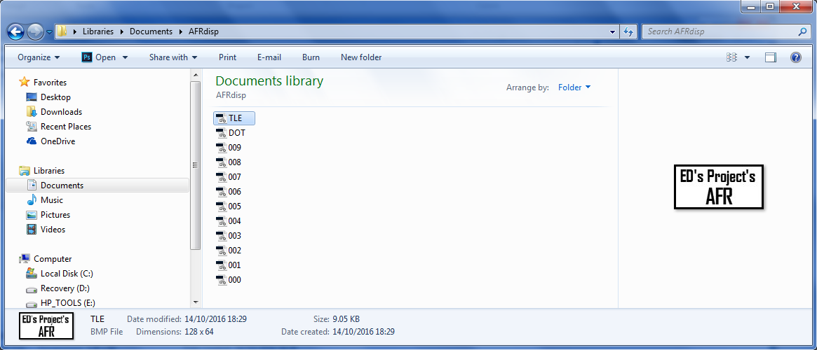
There are a few conditions for my SD card and those are that the images must be 128 x 64, the colour must be 8-bit grayscale and the image file must be a bitmap. Each of the numbers are image files of 36 x 128 and must me labeled as these are for the microcontroller to be able to find the correct image.
This project requires a wide-band lambda controller with a 0 to 5V output, there are lots out there but keep checking my projects as I will soon make one for myself. This meter is wires straight to the ignition, two wires, a negative and a positive. The yellow signal wire connects to the lambda controller. Normally a lambda will need around a minute to warm up before it's accurate.
Oh No!
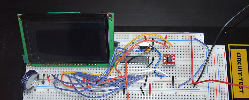
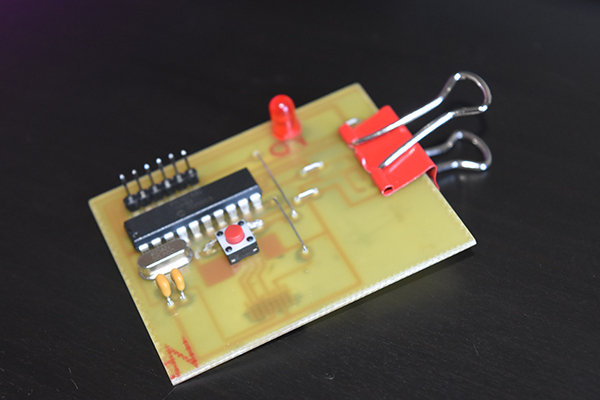
I chose to cast the display in resin, I had an accident with the SD card so re-programmed it and my program wouldn't read the card. To cut a long story short, my new SD card wouldn't accept SPI, the screen was stuck in resin and well, I needed to start again. Instead I chose to use a SPI memory chip instead of the SD. The first step was to test it on a breadboard, I had huge problems which turned out to be a defective display which would initialise only 50% of the time.
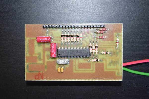
I proceeded in making a PCB design.
Here is the board completed, I added lots of capacitors to help smooth the supply due to the faulty display but it didn't make much difference.
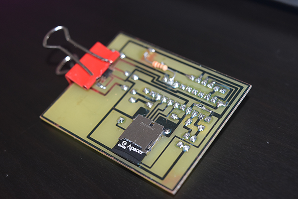
The second board I had to make was something to program the memory chip from an SD card.
The board complete, I used a clip to hold the chip in place while it was loaded with the data from the SD card.
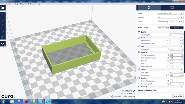
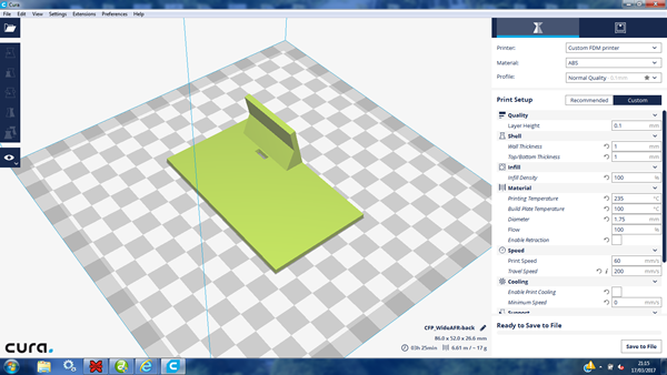
The next step was to make some kind of a housing for the display and then to 3D print it.
I had the display in my car for a couple of weeks and the display slowly began to fail, I really should have sent the defective unit back. I chose to replace it with an older one from another project, it worked perfect.
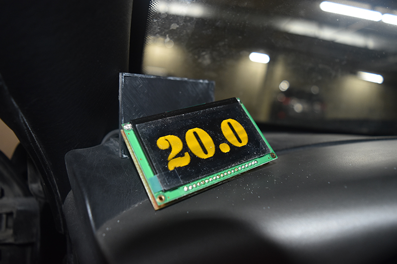
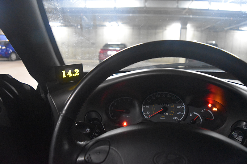
The display in it's housing.

The display working. I actually prefer this display to the other aftermarket ones due to the size of the characters, it was much cheaper too.
Hello, if you have enjoyed reading this project, have taken an interest in another or want me to progress one further then please consider donating or even sponsoring a small amount every month, for more information on why you may like to help me out then follow the sponsor link to the left. Otherwise you can donate any amount with the link below, thank you!