Nuclear Fusion - Z Pinch
When you hear nuclear probably one of the first things you think about is the nuclear bomb, destruction and radiation. Nuclear fission is the splitting of the atom (usually Uranium, Plutonium) whereas fusion is fusing atoms together such as that in the sun, hydrogen is fused into Helium atoms. Splitting of atoms uses a fuel that is heavy and fusion uses lighter fuels such as hydrogen. There are three main isotopes of hydrogen; protium (one proton), deuterium (one proton, one neutron) and tritium (one proton, two neutrons). Fusion of hydrogen has never been achieved on earth yet, only that of deuterium and tritium because these isotopes contain neutrons.
For me to attempt fusion I will be using just deuterium because tritium is radioactive and hard to source from suppliers, although fusion is easier to achieve with tritium as it requires less energy. When two deuterium atoms fuse together you get two main outcomes;
Deuterium + Deuterium = Helium-3 + neutron + 3.268MeV
Deuterium + Deuterium = Tritium + Hydrogen + 4.032MeV
With the results from the above another two reactions can take place;
Deuterium + Tritium = Helium-4 + neutron + 17.571MeV
Deuterium + Helium-3 = Helium-4 + Hydrogen + 18.354MeV
At the time of writing this I have very little experience in this field, my knowledge should progress as this page progresses. The purpose of this project is to achieve something that very few people in the world public have done so, nuclear fusion.
Just recently (April 2012) I did some research on pulse lasers which then led onto pulse supplies, bridge-wire detonators, nuclear weapons, nuclear fission, nuclear fusion and then finally the Z-pinch. All of these subjects I found very interesting, but the nuclear fusion is infact possible for the hobbyist and if I was to succeed then I would be among the youngest in history. The bridge-wire detonator is useless because its used for quickly detonating high explosives such as C4, TNT, etc... which in the Uk would land me in some serious trouble even to own any of these. The nuclear bomb is infact easy to make although again high explosives and highly radioactive makes it highly illegal. Nuclear fusion is not radioactive as such, contains no illegal explosives and is infact legal although still has the possibility of being dangerous.
Pulsed power Z-Pinch
The method for fusing atoms together involves extremely high temperatures and in some circumstances, pressure. A reactor contains an atmosphere of gas, usually a tritium and deuterium mix is used, I will be using just deuterium as its not radioactive, although it does require more energy for fusion to take place. The gas is first ionised to make it conductive and then electricity is passed though the gas which in turn produces plasma, the fourth state of matter. Plasma is extremely hot but quickly dissipates outwards, for fusion to occur the atoms must bash into each other, this does occur but if the plasma was to be compressed then the chances of fusion would greatly increase. With current flowing through the plasma a magnetic field is created, an outer magnetic field can react with this one to compress the plasma. The reason for the reactor being called the Z-pinch is because the plasma is flowing in the Z-axis on a mathematical diagram and it is being "pinched", compressed.
What I'm trying to achieve is the fusion of these atoms into Helium. There are four gas samples that I would like to take. Two fires at different atmospheric pressures and two fires of one with a field coil and one without. After each test I will collect the sample and then get them analysed to see what the content of Helium is, the more the more better. Another method is the use of a "bubble detector", it contains a resin that when hit with neutrons produces pockets of gas inside, these can be visually seen. The other although more difficult method is to use a sensor to detect the neutrons, the most common method is the use of a scintillator. Basically the radiation hits a crystal which emits a small amount of light, or known as a photon. The photon hits a high voltage cathode (usually about 1kV) which releases an electron, the electron travels down a tube containing dynodes which also release electrons when hit, at the end of the tube there is enough electrons to produce a voltage. The voltage is pulsed as radiation is coming in pulses, it is connected to a counter which displays the amount of radiation per second/minute/hour, etc... The problem with using this form of detection is that its electronic and the intense magnetic fields surrounding the reactor will create discrepancies in the readings.
Farnsworth-Hirsch Fusor
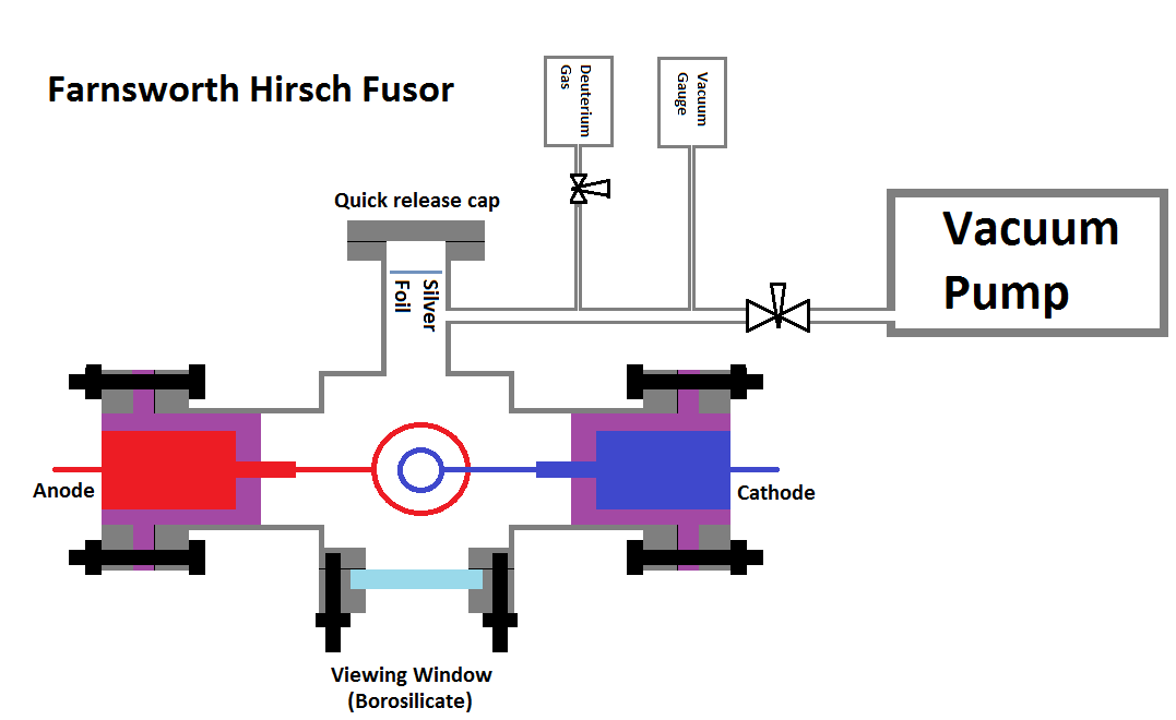
The Farnsworth-Hirsch fusor is by far the most common method to demonstrate and prove fusion. It is a vessel, usually stainless steel which consists of two electrodes. The two electrodes are a spherical wire frame, one is large, the other is smaller and inside the larger one. The larger electrode is connected to a positive source and the inner smaller electrode to a negative source, when power is flowing electrons move from the inner electrode to the outer creating a plasma(electrons flow from negative to positive). At the same time the Deuterium ions are positively charged and therefore accelerate towards the inner cathode. These ions miss the wire frame and occasionally two hit into each other to cause fusion to occur. This type of process is also known as inertial electrostatic confinement.
The Farnsworth fusor will only ever be used as a demonstrative tool as it consumes so much more energy than it produces. The problem with fusion is the density of the fuel and the confinement. With this type of fusor the concentration of deuterium is very low which means that there is a small amount of atoms present, a small amount of power will be required to make fusion happen, but the probability of collisions is very low.
Tokamak
This is the most hopeful design of sustained fusion and power production. Tokamak is an acronym for something in Russian, cant remember what it is but translates to; "toroidal chamber with magnetic coils". It is thought to be one of the greatest methods to achieve sustained fusion using Deuterium and Tritium fuel. In basic is a torroidal tube (doughnut shape) that is hollow containing the fuel, around this torroid is numerous electromagnets which are used to induced a current into the plasma and contain it. Due to the plasma inside the torroid to form as a ring, a current can flow through it therefore removing the need for electrodes. There are many problems to overcome which is the reason why fusion is still not powering anything, the main problem is harnessing the energy that is created. For my project I'm not trying to create energy, I'm only wanting to achieve fusion.
Capacitor Bank
A capacitor is an electronic component that stores electrical energy, compared to a battery the energy density is very low although high voltages and pulse currents are possible. About 5 years ago when I was 14 I purchased a large quantity of capacitors for a stupidly cheap price. Back then I made such projects like coilguns and railguns, nothing spectacular and only a working voltage of about 60Vdc. About a year after this I made a bank of these capacitors with a rated voltage of 450Vdc and an energy storage of 800Joules, note that only 16J is theoretically the lethal threshold. I eventually lost interest and stopped playing around with them.
Part of the Z-pinch will have a large capacitor bank which will be needed to fuse the atom, I could use the mains electricity but peak power levels would be far lower and all I'm trying to do is prove that I can fuse two Deuterium atoms to a Helium atom for just a split second. So I had a look around on the internet to see if I could build myself a capacitor bank cheap enough, after a lot of looking around and quotes I found some extremely cheap. The capacitors are 450Vdc, 1000uF, Nippon Chemcon (good quality) and have an energy storage of 101.25J. I first bought 20 of them as the expected postage time was 30 days, they arrived in under a week so I bought another 20. Below on the left shows my new capacitors (brown) and my old capacitor bank (blue). All 40 capacitors on the left stores a total energy of 4kJ at 900Vdc, five times that of the original larger bank. The blue capacitors are only about 10J each and are almost the same size. The white dust is glue vapor.
I have bought another 40 of these capacitors to build a bank rated at 900V, 20,000uF at 8kJ. 16J to kill, that's over 500times, its dangerous stuff so I will stay clear when its charged.
May 08/05/2012 - Age 19
I received the rest of my capacitors through the post today. I have also requested a quote on some acrylic sheet in which I will make a housing for the capacitor bank. I have ordered some PVC tubing for insulation of the bare copper wires.May 10/05/2012 - Age 19
 After quite a bit of gluing and soldering the capacitor bank is nearing completion. I have also ordered some acrylic sheet to make a housing for it, bare electrical connections at these kinds of power is far too dangerous.
To the left gives an indication of the size, compared to the previous bank it contains ten times the energy at approximately the same size. This is an 8kJ bank, the standard hospital defibrillator is a maximum of 360J, 22 times this.
May 15/05/2012 - Age 19
The capacitor bank is now complete, it is housed in 8mm of acrylic and to get a shock through this will be impossible at these voltages.
Before I go ahead with building the Z-pinch reactor I first must build something to discharge the bank completely incase of emergency. Usually a bank such as this will have a bleed resistor, but it takes longer and longer exponentially as the voltage decreases. Instead I will used a mechanical switch, due to the high currents the contacts may be demolished after one cycle, so these need to be removable.
When the reactor is triggered a residual voltage will still remain because this is not high enough to keep the plasma flowing, probably about 100V will remain in the bank, this is the other purpose of this switch.
May 31/05/2012 - Age 19
The project was put on hold for a short period due to other projects. Today I purchased some Deuterium oxide which I will electrolyse and use the Deuterium gas for the fusion. So far the project has set me back a total of £320 and I still haven't built the reaction chamber yet, fortunately I have most parts already, I'm guessing the final cost will be about £400.
June 05/06/2012 - Age 19
In the mean time I have been doing lots of research and adding bits to this page. Nearly all of the hobbyists that have built a fusor have built the farnsworth-hirsch design because its simple, gives off almost no electromagnetic radiation, easy to view and can run for a longer period of time. I'm still building the Z-pinch but the major problem is neutron detection. The only method that shows the proof of neutrons is by using a bubble detector. Analysing the gas at the end will prove fusion has taken place, it may be difficult finding someone to do this for me. Electronic detectors will be useless around the Z-pinch because the electromagnetic radiation will cause interference. If I was to build a farnsworth-hirsch fusor then I could easily analyse the results. I would buy myself some scintillation crystal and a photomultiplier to count the neutron radiation.
June 06/06/2012 - Age 19
I received my Deuterium Oxide through the post today, the reactor has been put on hold for the time being due to other projects. Probably be another couple of months before I start it again.
July 13/07/2012 - Age 19
Some more research and a lot of thinking has happened since last time I posted something on here. Now the fusion reactor that I was going to build was along the lines of the Z-pinch type but there are a few problems with this design, and from past historical experiences a better design was produced called the Tokamak. It is basically a toroidal shape surrounded by magnetic fields, an electromagnet induces a current into the plasma, external magnetic fields control the plasma "pinching" it, and keeping it in the center of the toroid. This design has been chosen to be the best method for the possibility of sustained fusion and energy production.
Before building something like this I have a few theories to prove, the first one being inducing a current into plasma and the pinching effect of a magnetic field. So to do this I'm going to build a Z-pinch.
July 15/07/2012 - Age 19
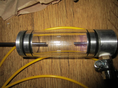
The Z-pinch will consists of a glass tube with sealed end caps, the tube will contain two tungsten electrodes and be filled with an inert gas. The gas that I have chosen is Argon because its cheap and easy to source. The two electrodes will be connected to an external resistor to limit current when the plasma is flowing and also measure the current. The gas will be ionised to make it conductive and then an external magnetic field will induce a current into the plasma, this will be the most difficult part. I will use a high voltage source to ionise the Argon gas, a high frequency induction coil will surround the tube. When the tube is at a certain pressure and the induction frequency is correct it can create the plasma. All of this is just proving that I can induce a current into a plasma and observe the "pinching" effect of the magnetic field.
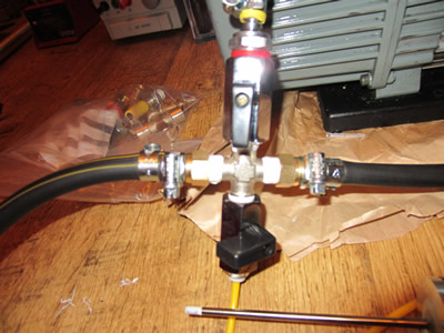
I have bought a disposable CO2 bottle, a regulator, two tungsten electrodes, a 15micron vacuum pump, a digital vacuum gauge and sent an enquiry about some glassware. All of this has not come cheap and stands me at about £285, but this should all help me in achieving fusion in the near future. This is not including the glassware which will add another £30 for the piece of glass tube, I have also enquired about some custom glass, a toroidal shape - hopefully not too expensive.
If I manage to induce a current into a plasma then I can go straight on to building the Tokamak. It will be tested on Argon first, and then Helium as it has similar molecular weight to Deuterium. After this I will submerse the whole thing in a tank of water and then test the operation again on helium. Once all tested it would be time to test it on Deuterium, the reason for submersing the whole setup under water is because the fusion reactor will emit neutrons. Water is one of the best methods for safely shielding neutrons, this is because the Neutrons hit the hydrogen atoms and turn them into Deuterium, possibly tritium. If the Neutrons hit oxygen atoms then it will either create another stable isotope of oxygen or an unstable one, the half-lives are short and the radiation is Beta which cant pass through the outer glass shell, the water will also absorb them.
 July 17/07/2012 - Age 19
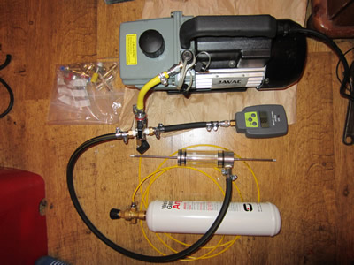
All of what I ordered has arrived through the post today. The picture on the right is just a stack of some of the parts that will be going into prototyping, building and running the fusion reactor.
The vacuum pump is a lot quieter than I expected and doesn't vibrate all over the place, so I can run it in my bedroom without any disruption to my home. The pump is rated to an absolute vacuum of 15microns (0.015torr) which is a very high vacuum compared to others on the market. The pressure gauge measures in the range of 15 to 12000 microns, I tested the pump down to 45 microns but the rubber tube I used to connect them was a bit leaky.
The bottom middle of the picture shows the tungsten rods for the electrodes and to the right of them are the bottles of Deuterium Oxide. I wont be making any Deuterium gas until I have tested the Tokamak at its penultimate stage on Helium submersed under water. I certainly don't want to waste any evaporating or stored gas leaking, far too expensive to risk.
Neutron shielding could be done in a different way with this fusion reactor, instead of using water, lithium-6 could be used instead. When neutrons hit lithium it produces tritium and Helium. Deuterium and Tritium is the best mix for fusion, using lithium to shield the Neutrons plays two parts as it stops the Neutrons from leaking out and produces fuel for the reactor. Tritium isn't really that dangerous and emits a low level Beta radiation, there is a certain legal amount of tritium that you can produce. Now I'm not going to use lithium for shielding but the reactor will still produce small trace amount of tritium, so I need to work out the maximum theoretical amount that it could produce and find out what the legal quantity is.
July 22/07/2012 - Age 19
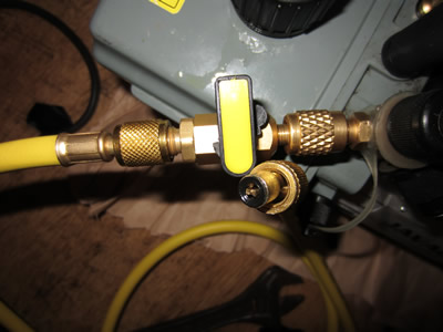
Since last time I have contacted another supplier of glass as the first one seems to be taking their time in replying to my emails. The new supplier has replied straight away and should be able to help with the glass toroid too. In the mean time I've been thinking about the pipe work for the gases, for some stupid reason vacuum systems use SAE threads, which I have never come across before. I have done a lot of searching for adapters to convert the thread to a standard BSP size, which don't seem to exist. The pumps are mainly used for the evacuation of the refrigerant in refrigeration systems, so I have bought a hose with the threads on the end, I will cut the hose in half and connect 1/4" hose barbs to them. I have also bought some nylon pneumatic tubing and various pneumatic fittings, it stands me at a total cost of; £34.
I have been doing a lot of reading about fusion theory, etc... A couple of the websites claim that one gallon of sea water has the same potential energy of three hundred gallons of petrol (gasoline) using Deuterium fusion. This sounds quite a statement when there is only a couple of ml of Deuterium in a gallon of sea water. So I thought I would do a little maths to see if this is true. Assuming 1ml of water is equal to 300ml of petrol.
In one water molecule there are two hydrogen atoms and one oxygen atom, the atomic mass of hydrogen is 1.00794g/mol, and oxygen is 15.9994g/mol, therefore there are 18.01528g/mol. There is 6.022×10^23 molecules to a mole. Therefore (6.022×10^23) / 18.01528 = 3.342717959x10^22 which is then multiplied by 2 to give the total number of hydrogen atoms per gram = 6.685435919x10^22. So if there is one deuterium for every 6420 hydrogen it will be; 6.6911x10^22 /6420 = 1.041345159x10^19 atoms of Deuterium atoms in 1gram of water.
The fusion of Deuterium + Deuterium (D+D) yields 3.27MeV per atom. ((1.041345159x10^19) /2) * 3.27 = 1.702599334 x 10^19Mev.
1 electron volt = 1.60217646 x 10^-19 Joules. (1.702599334 x 10^19) x 1.60217646 x 10^-19 = 2.727MJ
This means that there is a total energy of 2.73MJ of D + D fusion in just 1ml of water, therefore 300ml of petrol should equal this. Note I have used 1gram/1ml of water as the same thing, this is because 1ml of water = 1gram, this will not be the case for petrol and I shall use volumetric units.
Petrol (gasoline) is about 35MJ/L. 35KJ/ml. 35000*300 = 10.5MJ
In the fusion of Deuterium there are four possible outcomes;
D + D = Helium-3 + n (3.268MeV)
D + D = T + H (4.032MeV)
D + T = Helium-4 + n (17.571MeV)
D + Helium-3 = Helium-4 + H (18.354MeV)
Overall this requires a total of six Deuterium atoms and produces an energy of 43.225MeV. This yields an energy of 12MJ from 1gram of water, compared to the 10.5MJ in 300ml of petrol (gasoline). I'm pretty sure that my calculations are correct, so that means that the sites have copied from one another or I have used a different figure for the concentration of Deuterium in water. The results are still very close though.
July 23/07/2012 - Age 19
I received the quotation from the new glass supplier today, £110 for a piece of borosilicate glass tube 40OD, 30ID, 100mm long. The original glass supplier quoted me £27.97 including delivery of 3-5 days unlike this one that does not include delivery and has a turn around of 4 week. As for the custom glass toroid, 120mm OD, 40mm ID, 40mm cross section, 5mm wall. Between £500 -1000!!! No thanks.
July 29/07/2012 - Age 19
 A couple of days ago I received all of the items that I bought including the glass tube. The first thing that I did was to try out the vacuum hoses, I don't want them sucking in atmospheric air that will contaminate the gas. I connected the vacuum pump to the valve, then the hose, to the pressure gauge and turned it on. The vacuum quickly went to 600 microns and then slowly decreased to 300 microns, I shut the valve and the pressure quickly raised up to 2000 microns, clearly these seals are not up to the job. I did a lot of reading and found out that these types of sealing gaskets are useless for these types of vacuums and that I need hoses with O-ring seals instead.
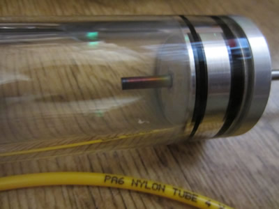
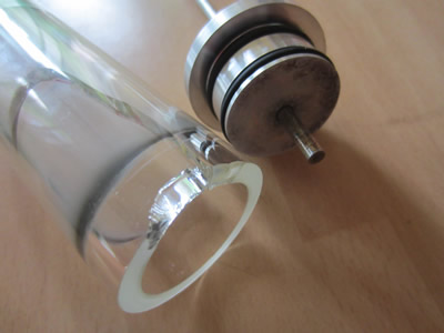
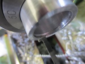
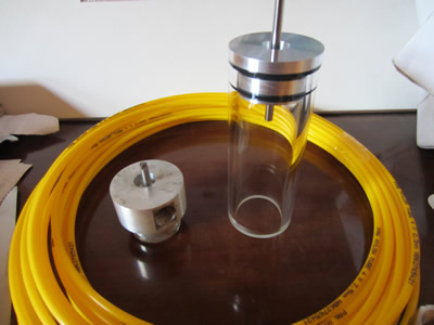 Today I machined both of the end caps for the Z-pinch from aluminium. I included two O-rings at two different cross sections to provide the best sealing possibility and machined a recess at the end of the caps so that I can fill it with resin to seal the electrodes.
One of the end caps was machined an extra 15mm long so that I could screw a BSP connector to it, this is so that the tube can be vacuumed and filled with gas. Unfortunately I made a stupid mistake and forced the tungsten electrode through it, I got half way and it got stuck. I tried pressing, heating it up and hammering to no avail, and ended up smashing the electrode. I will have to make another and spin the reamer in the hole a little longer to open it out. A lot of the fittings that I'm going to use are push-fit pneumatic and I don't know if these will seal a vacuum, if all else fails I will use adhesives. As for my pump I will make some plastic spacers and use O-rings to seal the connectors, If this fails I will braze a BSP adapter to the pump.
August 05/08/2012 - Age 19
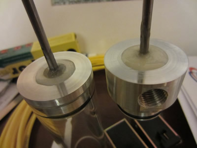 A different seal was tried in all of the connections, PTFE and O-rings but neither of them worked. I'm now thinking it may be the hose itself where the connections have been crimped. I have contacted the supplier of the pump to see if they can supply me with a hose that seals or hose barbs, hopefully I can get this all sorted pretty soon. A couple of days ago I decided to machine the end cap again, luckily this time the tungsten rod was undersize so didn't get stuck in the hole. To seal them I use a polystyrene contact adhesive because it sets like a soft rubber, I then filled the rest of the hole with a resin to assist in sealing and add rigidity.
Now that I'm getting very close to firing the Z-pinch I need to think of ways to ionise the gas inside of the tube. Having electrodes inside of the tube makes ionisation a lot easier, I think that the toroid way need electrodes incorporated into it otherwise high frequencies would be needed. To ionise the gas a high voltage must be present across the electrodes, once a current is flowing then the voltage can be dropped to a sensible level. Many lamps such as Sodium, fluorescent, HID, etc... operate in the same principle, so basically to run my Z-pinch it will require the starting circuit such as that found in a HID lamp starter.
August 08/08/2012 - Age 19
Today I found a place near where I work that sell pneumatic fittings, I brought the pressure gauge with me to see if they had any threaded components that would fit it, 7/16 SAE hose barb did. So I ordered two 1/4BSP hose barbs, two 7/16SAE hose barbs, four hose clips and two 1/4BSP ball valves. When I got home I connected the pressure gauge to a hose barb, pipe, hose barb, ball valve, hose barb, pipe, hose barb and then the pump. Switched it on and got down to a vacuum pressure of 50 microns, turned the ball valve and the pressure rose slowly. I then connected the nylon pneumatic hose between the pump and vacuum gauge using the push-fit connectors, a vacuum didn't even register on the gauge.
August 09/08/2012 - Age 19
 I went back to the same shop and bought a load more fittings. I connected it all up and used loads of PTFE tape on the threads and two hose clips on the hose barbs. The lowest pressure that I can achieve is 60 microns, the whole system still does not hold a constant vacuum but its good enough for me.
One problem that I have encountered is that my vacuum gauge is a bit temperamental. When pulling a vacuum its ok, but when I open the valve to let Argon into the system the pressure rises but only to a certain amount. I think that it may be a fault with the gauge or a block in the tubing to the gauge, at the moment I'm unsure.
August 11/08/2012 - Age 19
 Today I thought I should have play with the Z-pinch running on argon gas just to find out what kind of voltages ionise the gas at different vacuum pressures.The only high voltage source that I have is an old power supply from a plasma globe, the voltage is circa 5kV.
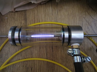
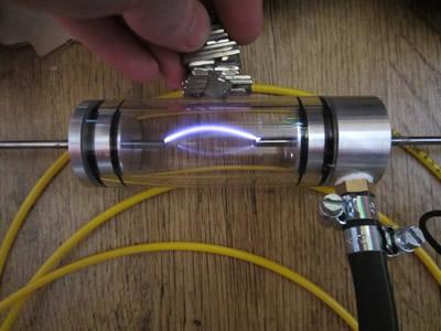
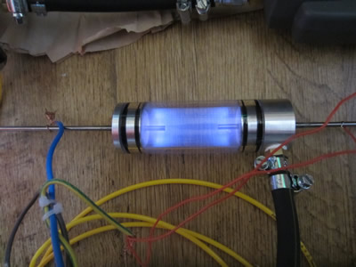
I first drew a vacuum and then filled the tube with argon gas. The picture on the far left shows the arc on a vacuum too small for the gauge to register, the picture on the right shows the plasma reacting to a magnetic field. Outside in air this arc would only be about 5mm long, the gap between the electrodes is 40mm.
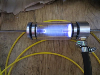
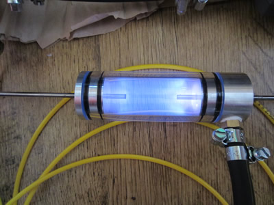
The pictures from left to right show the vacuum increasing (pressure getting lower). 1000micron, 500micron, 200micron.
The picture below on the left and middle shows a magnetic field reacting with the plasma. The picture on the right is it running on a vacuum of 60 micron, the arc is almost invisible because the voltage is not high enough, you can see a faint purple glow around the right electrode.
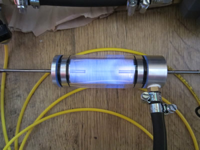
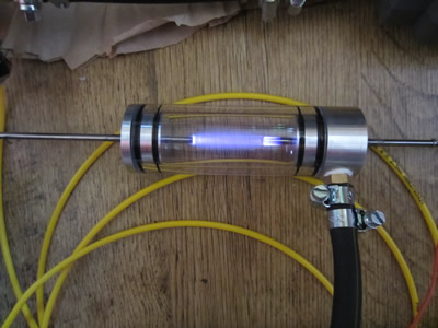
Below shows the tube running at 500Vac on a higher current power supply, about 1A max. At the far left shows the tube running at a pressure of 200microns, at lower vacuum pressures the arc almost disappears, probably because the voltage is too low and very little argon is present. When the pressure is brought up to 500 microns the electrodes start sparking, at 550 microns and above a violent arc occurs which rapidly heats the tube, as shown in the center picture. The electrodes have gotten so hot that they have turned purple, the main problem is that the aluminium end caps act as electrodes causing the arc to burn the O-rings.
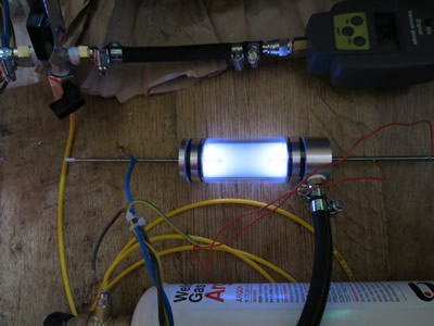
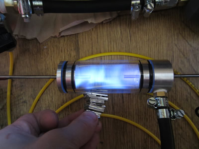
 When I decide to run the Z-pinch on Deuterium it will be run on DC (direct current) from a large bank of capacitors. I connected my 450V source to a bridge rectifier to get DC, I ran the Z-pinch at a pressure of 1000microns, 430Vdc at 1.5A (645W). The results look similar to this one on the right, except for the arc was far more intense. The result was that the disc of plasma around the end cap heated it up so much that it melted out the glue and burnt the O-rings.
Unfortunately when I removed the end cap the glass chipped and a crack shot half way down the tube, as seen on the left. To go any further with the Z-pinch I realise that the electrodes must be shaped into the glass, I was originally going to use PTFE discs to block the aluminium but I now realise that it wouldn't have worked.
I'm going need some custom glass work doing this time, I may also have a water jacket placed around the outside to keep it cooled, not really that necessary for pulsed power but the water will act as a neutron absorber. So far I'm quite pleased with what voltages are required and I almost certainly think that 900Vdc will be high enough.
August 27/08/2012 - Age 19
Thought I should write something since its been a long time since I wrote anything about this project. I have recently just started building an induction heater rated for about 2.5kW (although could run to 5kW if wired into mains), there are a couple of reasons for building one of these, the main one is because I started it two years ago and due to financial issues never finished it. One of them is because I want to attempt to produce sodium metal from salt which will be explained in another topic. It ties in with the Z-pinch because I shall attempt to inductively couple plasma, an induction heater works like a transformer but induces a current into a work piece, the work piece acts like a shorted secondary and heats up. Plasma in this case can act like a secondary because it conducts, now at a certain atmospheric pressure and frequency a plasma can be spontaneously started meaning that I could create a Z-pinch without electrodes, I would be the first in the public to create a fusor without electrodes. If I was to create a doughnut shape, place a coil around it, using the induction heater I could induce a plasma, it may be possible that this is enough to start fusion. If not then I could connect the capacitor bank the heater coil, switch off the heater and pulse the current through the coil while the plasma still remains.
I'm still going ahead with the Z-pinch and attempting fusion with that first because it will make things so much easier. Firstly I need to get the custom glasswork made, I wouldn't like to think how much it could cost, but I going for a design that makes it easy for the manufactures, aesthetically it doesn't need to be pleasing.
September 30/09/2012 - Age 19
Forgot to update this page, about two days after writing this log I received a reply saying they couldn't assist me in my request. This project has been put on hold again due to certain circumstances, it will be probably be another couple of weeks before I start it again.
February 25/02/2013 - Age 20
Its been a very very long time since I did anything on this project, since last time I have done very little research. Now that I have reached the age of twenty I realise that time is running out, I start university in about a year and a half from now, while I'm earning money I must complete all of my projects, especially this one. Over the last few days I have done a lot of thinking on this subject, I have thought of some theories and ideas of how to create fusion.
April 20/04/2013 - Age 20
I started re-designing and building my air rifle again, so this project got put on hold. Now my rifle is reaching completion I have realised that I must start and finish this project, so I did a little more on it this weekend. The capacitor bank requires some high power switching gear, which basically will consists of eight trigatrons, one for each 1kJ bank. A trigatron is a spark gap that is triggered by a tertiary electrode, this electrode is connected to a high voltage source which causes ionisation between the two main power electrodes, therefore allowing power to flow. Everything I design is built to last, which means that anything that wears can be replaced. The electrodes that I'm using are tungsten lanthanated which are mainly used for TIG welding, there are many different grades but these have the best attributes and unfortunately are the most expensive. I bought twenty 4mm electrodes and twenty 1.6mm electrodes which came to a total of £115, these were almost half price, still very expensive.
The terminals that hold these electrodes must be durable and easy to release so that the electrode gap can be adjusted quickly and easily. I though of many different designs, the best I thought of was to used pneumatic clamps. I'm not quite sure how long the electrodes will last, maybe one shot or fifty before the gap has to be adjusted. Making the system pneumatic means that they can all be released, adjusted and clamped simultaneously. I needed to make a total of 24 clamps, 16 of them are carrying the high current and 8 of them are carrying the trigger current (very low). I started making the high current clamps.
April 27/04/2013 - Age 20
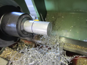
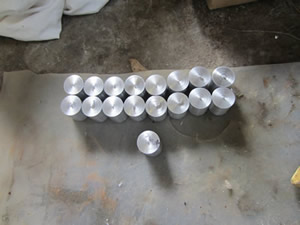
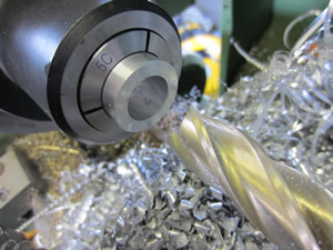
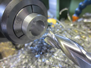
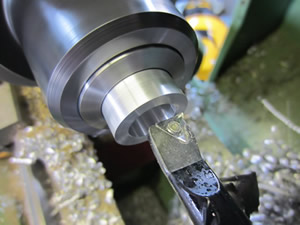
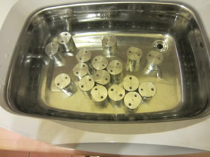
Over this past week I have stayed behind after work to get some parts done on the miller, I have spent a lot of time machining these, I certainly wish I could have used a cnc lathe. Below are some pictures;
I used 1" aluminium bar because its the maximum diameter that can fit all the way through a 5c collet, its cheap and aluminium is one of the best conductors. I started by facing the material, removing the nipple with a centre drill, machined the OD to 25mm and then parted them off at a length of 30mm.
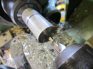
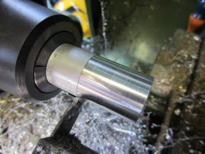
It was best to do just one operation at a time which is the reason why I parted off several blanks. I next faced off the parted side to an exact height of 30mm, centre drilled and drilled to a depth of 22mm.
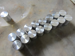
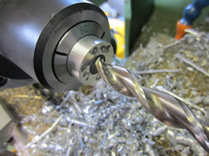
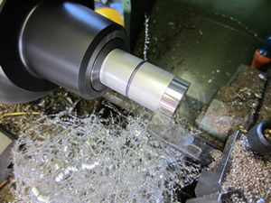
I drilled to a depth of 16mm using a 16mm end mill, just to take some of the meat out for future boring. I then used a 12mm slot drill and drilled to a depth of 22mm, a slot drill can be used for solid material, an end mill needs a pilot hole. I then bored it out to a diameter of 20mm at a length of 15.5mm, I then used a grooving tool to make a retaining groove for an internal circlip.
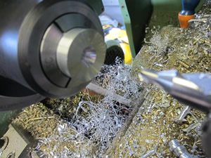
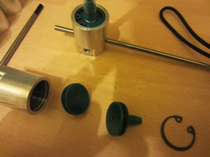
Unfortunately I did all of the milling at work and forgot my camera. Firstly I polished the bores, then I machined two holes with an M4 thread on the bottom, these will be used to hold the clamps down. I drilled and reamed a hole through the side, this is to hold the tungsten rod, I then milled a flat and drilled a thread perpendicular to this to allow for clamping the power wires. I deburred all of the edges and placed the parts in an ultrasonic cleaner to remove all oil and dirt. I machined some pistons and hose barbs out of acetal because its cheap, easy to machine and durable. I assembled the parts and tested on, it worked perfectly.
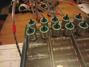
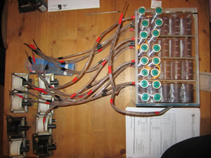
To trigger the trigatron I need a high voltage source, I found some new ignition coils on an auction website for £5 each, they may be a little overkill but a cheap alternative, so I bought eight of them. I have also bought some hose connectors, high voltage wire and some panel voltage meters. I had a little play with one of the trigatrons, discharging 900V at 200J into a pancake coil, launching a two pence coil eight foot into the air.
May 19/05/2013 - Age 20
About a week ago I ordered some plastic sheet to build a case so I don't end up touching something that I shouldn't. I have received this plastic, it just needs drilling out. I'm not in any rush because I ordered some tube connectors to link all of the clamps together, they still haven't arrived yet. I also need to make some clamps for the trigger electrode, they don't need to be powerful as they're not holding any current, I'm just not quite sure whether to make them from metal or plastic. Its just over a year since I started this project.
April 14/04/2014 - Age 21
Now its getting up to a total of two years since the start of this project and I have yet to finish my setup or even attempt fusion. I currently have many projects on the go but need to get some of them out of the way, luckily I have a break week of my educational studies coming up, so I should be able to crack on with the project. I have had a good idea about the triggering of the trigatrons, instead of using the ignition coils that are bulky and require a circuit to go with them, instead I'm thinking about an igniter transformer. Ideally I want to be able to control all eight of the capacitor banks independently, there is one other project that I can test this on first.
April 22/04/2014 - Age 21
I'm getting a little impatient with the whole fusion thing, Z-pinch fusion will be very hard to achieve and I'm not even sure that I will be able to do it. On a side line I'm going to perform fusion with a Farnsworth fusor. I will be pretty much starting again as I need to buy a high voltage power supply and build a confinement vessel, but I have the tools to do so which I never had previously. The TIG welder should be very useful in making the vessel and the spherical grids.
April 23/04/2014 - Age 21
I'm definitely going ahead in making a Farnsworth-Hirsch fusor and will be starting construction very shortly, below is a plan of my setup;
Hello, if you have enjoyed reading this project, have taken an interest in another or want me to progress one further then please consider donating or even sponsoring a small amount every month, for more information on why you may like to help me out then follow the sponsor link to the left. Otherwise you can donate any amount with the link below, thank you!