The Microcontroller
I'm not going to explain too much on what one of these is because the name is pretty self explanatory. In basics it's a small computer that can be programmed to do a function, it normally consists of several inputs and outputs and can perform special functions such as read analogue or output serial information.
The microcontroller I use most often is the 16F628A, it is the most commonly used chip and there's plenty of information out there if one gets stuck. From no background of microcontrollers it can be quite difficult to grasp at first what everything means and how they work but all datasheets give a block diagram such as the one below, datasheet from www.microchip.com.
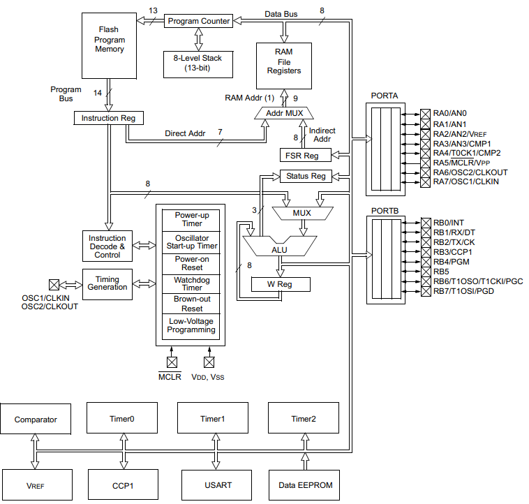
To be honest this diagram has very little to do with programming the chip but it's very helpful in knowing how a microcontroller works. It may be better to get a dedicated book as I'm going to quickly skip through it.
So firstly all of the program is saved in "Flash Program Memory" and this can tell any of these other blocks what to do.
After this it goes to the "instruction Register", this does exactly as it says, the program instructs data to be moved to a specific location. So for example PortA or PortB are used for external inputs or outputs, these are normally bi-directional but first must be configured whether they are input or output. This instruction could tell all of PortA to be outputs. The next instruction could then output some data through PortA.
The "MUX" is known as a multiplexer, it can stream two pieces of information simultaneously instead of one then the other, that's all you need to know.
The "ALU" arithmetic logic unit is the main brain of the microcontroller and is what does the maths, very much like a calculator, most information will run through this.
The "W Reg" working register is the most important part you will come across and is used directly in the program. It's like a bucket, it holds the data that you need to move. So for example some data from the program memory could be placed in the working register, the working register could then move this data to PortA.
Other two important blocks are the "status register" and the "RAM file register". The status register is easier to explain later on but say for example you choose to add two numbers together, 100 + 200, the maximum data you can hold in 8-bit is 255, adding these two numbers gives 300, the status register will indicate there is an over flow, an extra bit to carry which could then be stored in another location. The status register has many more uses, the part I discussed is known as the carry register. The RAM file register is what holds temporary information, they are known as variables, it will become clear later on what it's used for. (RAM - Random Access Memory).
The next part to discuss is program memory as this holds the program I have written, it could tell the chip what to do whether it's to configure ports, clock speed (processor speed) and many more other options. So firstly there are things called memory stacks, these are subroutines, so a program could shoot off elsewhere via a subroutine to do something different, this program is processed in another memory stack and then finally returned from where it left off in the original program stack, these can be stacked up to 8 times. Some other chips allow 16 stacks and some can be programmed to run for up to 256 stacks. The program stack is a convenient way of a chip knowing how many subroutines have been called up.
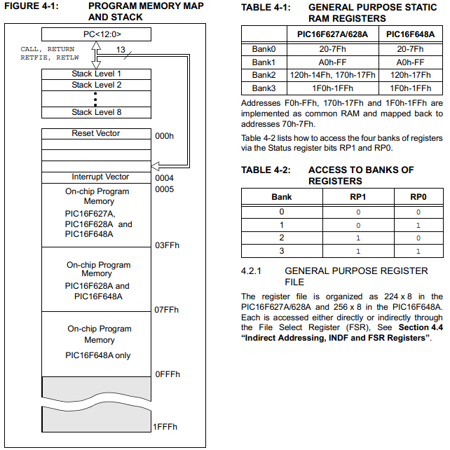
Now since its all just a stack of memory there is always a start location, that being 0, it will run through the list of memory until it reaches an "END" command. The reset vector and the interrupt vector will be explained at a later date, it is the memory location 0005 that I start writing my program at. Since the chip will read all of the memory in sequence and nothing is written in the reset or interrupt vector it will just skip forward and start from location 0005.
Another very important part are the register banks, these tell the data what to do. So for example if bank 1 was to be selected then the data sent to it could configure what ports A or B are to be defined as - inputs or outputs. If bank 0 was to be selected and the same data sent to it then it could just output the data from either port A or B. This will become clear in the next diagram.
This is another purpose of the status register, so if I was to set the status of RP1 to 1 and RP0 to 0 then bank 2 would be selected.
Image taken from datasheet, www.microchip.com
In a datasheet there will be a couple of pages showing the data memory maps or banks of registers.
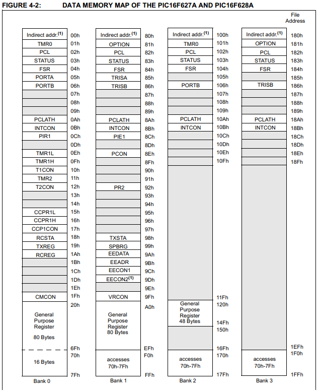
In time it comes clear what all of these mean but there is always a datasheet to rely on. It is really helpful to get to terms with understanding what all of these mean because there isn't just one chip out there, there's thousands and while most of these data maps are the same there are also loads of extra's to explore.
So earlier when I talked about setting the status to Bank 1 and sending some data to Port A, or in this case it is called TRISA. Now it depends how this port is configured to determine what pins on Port A are inputs or outputs. The chip is 8-bit, so an 8-bit number is sent to TRISA, for example; 01111110. This would configure pin0 and pin7 as outputs and the rest of the pins as inputs.
I could then switch back to Bank 0 and send some data such as; 00000001 to Port A and it would make pin0 high. Alternatively I could choose to run from Bank 2 or 3, although generally not used as everything is normally in Bank 0 and 1.
Even if I was to send 11111111 to Port A since only bits 0 and 7 are configured as outputs only the pins 0 and 7 would be high, the other would be unaffected as they are inputs.
Image taken from datasheet, www.microchip.com
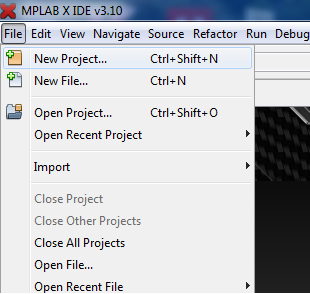
Ok, so I hope you get the basic understanding that all these chips do is move data around depending on how you configure register and what data you want to move. Later on I will show you what all the programming is about but first you will need a software / compiler. There are quite a few programming choices, such as basic, assembler and C. You want to be using assembler to get the fastest running chip, I only know assembler so that is our choice, the best software is Microchip IDE which does have the option of C if you choose that path later on. I'm not going to explain how install the software, it's easy and it's also free to download. Follow these steps and you should not go wrong in creating your first program.
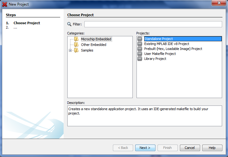
Firstly open a new project.
Standalone project, then next.
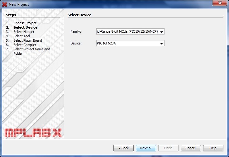
Make sure to select "Mid-Range 8-bit MCU's" in the family option and then PIC16F628A for the device.
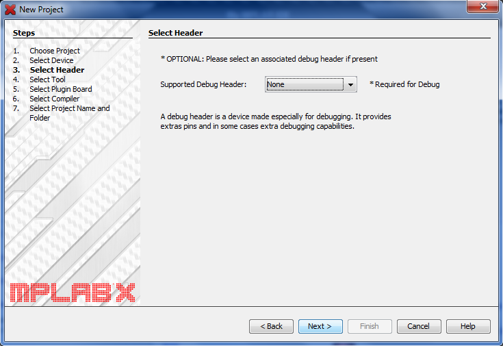
Leave as "None" and click next.
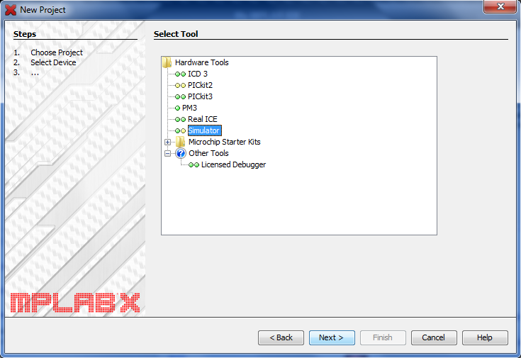
This is what you will use to program your chip, you can choose the simulator which uses the software, it allows you to view pins and variables. You will need some kind of a programmer eventually, I chose the PICkit2, it will program virtually any chip and it's a cheap option.
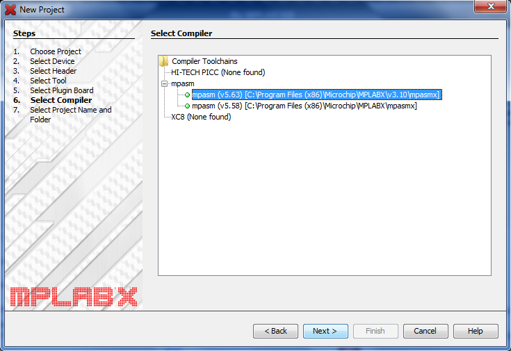
Click the latest option of the software, there should only be one available (unlike mine).
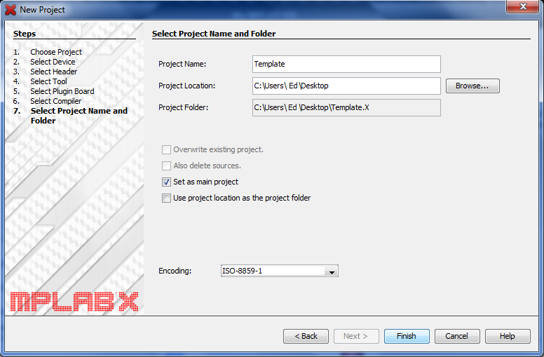
Then choose your project name, note that this is not the actual program file, it is just another folder name.
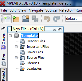
Once complete you will need to create a new file, ignore all of the other folders it provides, click on the main folder and add a new file.
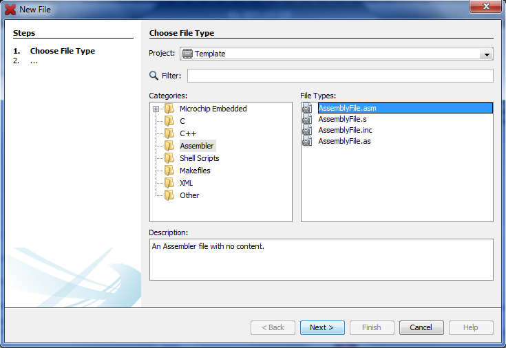
The programming language I prefer is assembler so click this folder and then "AssemblyFile.asm".
Then name the program file.
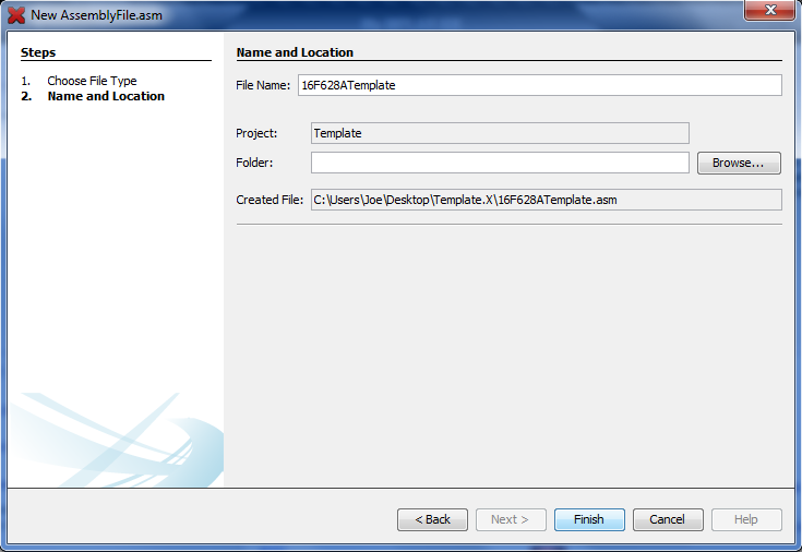
I have created a template of what is needed before you can create a program, I will provide a link below the picture for you to download the template. I have added a little description of what the commands do, I will go more into detail in the next project, this is just to give you an idea and to get your programmer to work. It is certainly worth labeling everything in the program, everything preceded with a colon will be ignored by the software. If everything is labeled then when it comes to building the circuit or debugging the program then it will certainly make it a lot easier, it also makes it easy for others to follow.
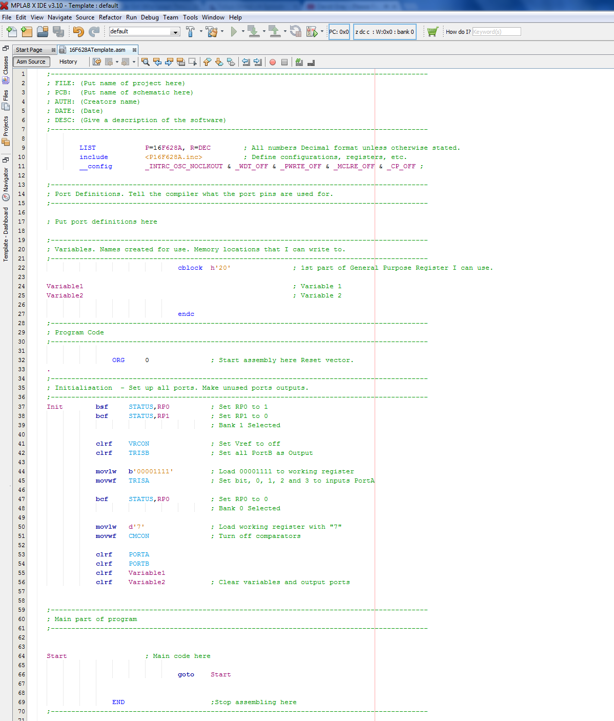
Saved is a notepad text file, just open it, copy and paste into your project - Template
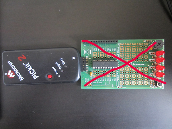
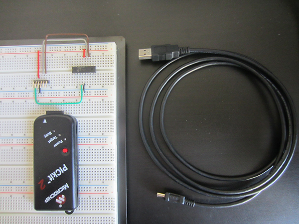
Now it's time to sort the programmer out, I really recommend getting the Microchip PICKit2 as it's all you will ever need. The chip that comes with it is the 16F690, it's a little less common but slightly more capable. It would really be a good idea to go with the 16F628A as it's not just straight forward as plugging the chip onto a board and then programming it, with using a breadboard it gets you used to what pins you need. Here are the parts you will need;
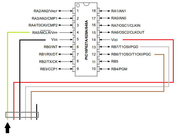
Below is a circuit diagram of the programmer to the chip. Note that you do not need an external power supply as this is provided by the programmer.
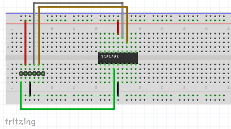
Below is a digital representation of the breadboard so you know where all of the components are to be placed.
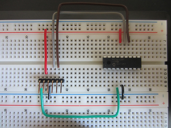
Below is my version on a breadboard, it may differ slightly from the above.
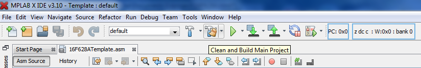
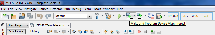
To program simply click on the "Clean and Build Main Project" Icon, at the bottom of the screen a series of checks will be displayed, at the end it will either say "Build Failed" or "Build Successful". If it fails scroll up this writing and click on the red writing and that will direct you to the part of the code that is incorrect, cross reference it with mine to correct the issue.
Now if the build has been successful it is time to program the chip by clicking on "Make and Program Device Main Project". If for some reason this becomes greyed-out, go to "file", "project properties", select the "pickit 2" icon and click "apply", you should now be able to program.
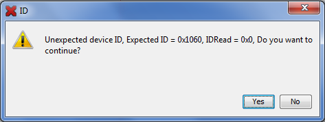
If it does not program properly it will come up with the following warning, it is just explaining that it has not found the start location of the chip, check all of the connections. If there is no message at all and the program button disappears then there is an issue between the computer and programmer itself.
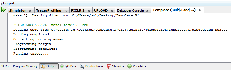
You should get the following if the programming has been successful.
Now you know how in basic terms a microcontroller works, what hardware you need and how to program a chip, you now want to use some kind of input and see an output to prove you have programmed a chip correctly.
Hello, if you have enjoyed reading this project, have taken an interest in another or want me to progress one further then please consider donating or even sponsoring a small amount every month, for more information on why you may like to help me out then follow the sponsor link to the left. Otherwise you can donate any amount with the link below, thank you!