Microcontrollers 2 - The Flashing LED
Be sure to check out the introduction before this page on how to get to grips with the software and just a basic program to make sure the programmer is working correctly.
Ok so this always seems to be the first tutorial on microcontrollers but it is a very valuable one, the problem I found when I first begun learning is that nowhere seemed to explain why I was writing certain code or what it all meant. I'm going to base this tutorial off the 16F628A again as it's nice to work with, if you need the basic template then follow link - Template
The only thing I'm not going to do is post a link to the completed program, you only learn by writing it out yourself, it's easy to copy something but when you choose to do your own project you will essentially be starting again. Below is the program, I have split it into a few sections and after the program I will explain what every command does so you can cross reference it with the program. There is a chapter further on that explains all of the commands in a little more detail, microcontrollers 4.
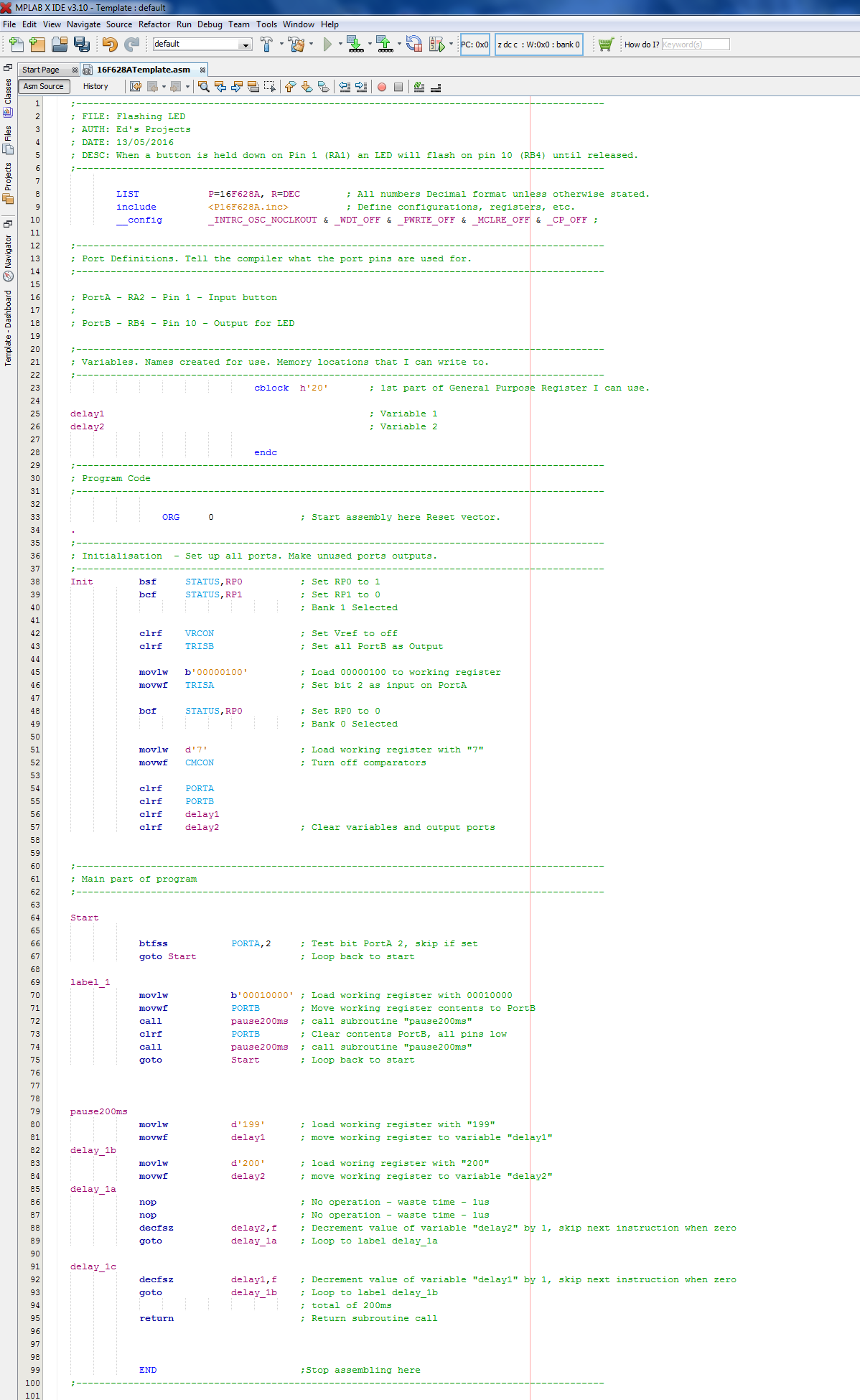
The first thing to note is all of the green writing, these are just comments and so long they are preceded by a colon they will be ignored by the software. The first part of the program is the "List" and "Include" these are just instructions to the software telling it what chip I intend to program. The "_Config" is a very important instruction, leave it the way it is, it's very useful for setting special features such as higher clock speeds or power saving modes.
Between "cblock" and "endc" is where all of the variables are labeled, again this is something for the software to translate when it programs the chip, it is to make using variables easy for the user by allowing them to specify their own names.
"Org 0" is the origin of the program start, this is almost always going to be 0 and needs no further explanation.
The purple writing are labels, the dark blue instructions, the light blue registers and the yellow is data.
The first instruction "bsf STATUS, RP0" means bit set file the status of variable RP0, so bsf mean to put the value of 1 into status RP0 which in turn selects bank 1 of the registry map. The opposite of "bsf" is "bcf", bit clear file, so this would send the value of 0 to what ever the variable is, such as in the following instruction, "bcf STATUS, RP1".
Where the "bsf" and "bcf" instructions only deal with one bit, the "clrf" instruction will clear the whole registry, clear registry file. So the "clrf TrisB" will completely clear this registry and set all of PortB as an output port.
"Movlw" moves data into the working register, so "Movlw b'00000100' " will load the working register with this binary number. "Movwf" moves the contents of the working file to wherever, in this case, "Movwf TRISA" will tell bit 2 of PortA to be configured as an input.
"VRCON" and "CMCON" will be explained in a later projects, these need to be disabled in order to use all of the pins properly.
"call" tells the program to jump to a subroutine, wherever the call was initiated from it can be returned to by the "return" instruction.
"nop" just wastes an instruction cycle, 1us, an instruction cycle is a quarter of the clock frequency.
"decfsz" decrement file register, skip if zero. This will decrease a variable by one and read the instruction below, once the variable reaches zero it will then jump this instruction below.
I'm pretty sure that you can work out what the program is doing from this, the delay system is known as a nested delay. So if each instruction is to take 1us, the first loop will work out to 1ms, the nested loop will then multiply this to 200ms. The decrement command will take 2us when it skips, the no operation commands are very helpful in getting a precise time delay.
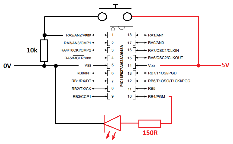
Once you are happy with the program it is time to get it working, so do as you did in the previous project, the software will tell you when the program has been completed. The next step is to build the rest of the circuit onto a breadboard, the pin layout is below;
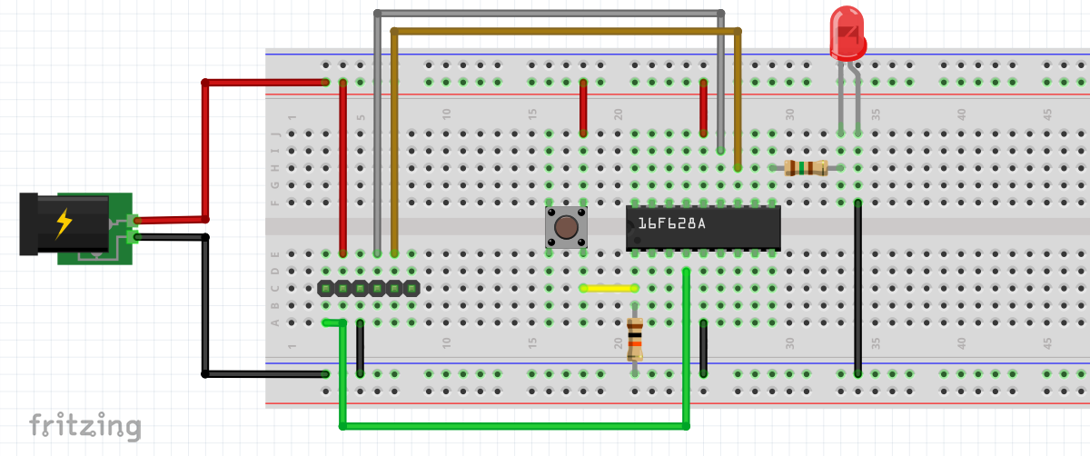
I have included a breadboard layout so you know where to put the components.
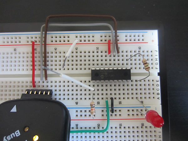
Below is my version of the breadboard, it does vary slightly but does the exact same thing.

So you have managed to get your chip to do something and have a basic understanding of what the commands do, it is now time to understand what the configuration symbols mean at the start of the program. Something I would recommend doing is building your programmer onto a board, basically a male header with a chip holder, it saves cluttering the breadboard and stops damage to other parts of your circuit if high voltage programming is used.
Hello, if you have enjoyed reading this project, have taken an interest in another or want me to progress one further then please consider donating or even sponsoring a small amount every month, for more information on why you may like to help me out then follow the sponsor link to the left. Otherwise you can donate any amount with the link below, thank you!