Microcontrollers 3 - Special Configuration Settings
At the start of a program such as in the example below there is some purple writing after the config symbol, these are known as the special configuration settings or features. These settings can determine the clock speed, whether it's external or internal clock, program protections, etc...
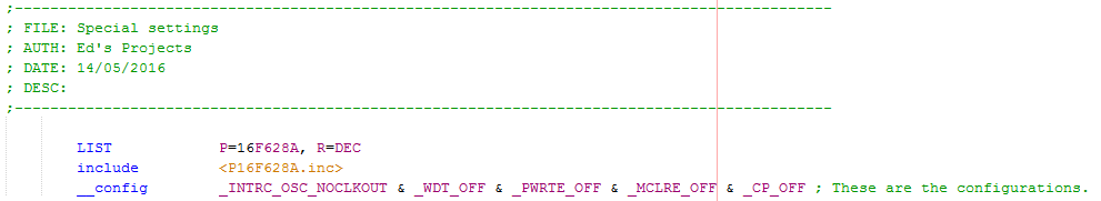
It is very useful to refer to the manufacturers datasheet to know how these are configured, although they are mostly the same throughout the microchip range when you do get onto the bigger chips with more than one configuration setting and more functions it's useful to get used to finding where these are in the datasheet. There are also two options of writing the configuration settings, in the format above known as "symbols" or in a 13-bit number known as a "word". Note that not all of the symbols will be listed in a datasheet as it's not the chip that recognises them but the software, the software converts it into machine code that the chip will recognise, however in most cases the name of the register or the bit in that register will be recognised as a symbol by the software. Below is an extract from the datasheet.
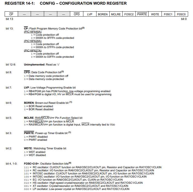
As you can see it's quite easy to cross-reference between the purple writing and what is in this datasheet, what may not be clear is what all of these functions do, again it may be helpful to refer to the datasheet although I have provided a quick summary.
CP - Flash program memory code protection - this is the main code that is protected, if enabled it cannot be read by hardware, for example it will stop a third party from stealing your code.
CPD - Data code protection - similar to the above except it is that EEPROM that's protected.
LVP - Low voltage programming - The pin labeled PGM (RB4) can be used to program the chip via low voltage programming, so when this is raised to +V the chip will enter programming mode. It is worth disabling this setting as the PGM pin can then be used as a multipurpose input. When disabled the chip is programmed in HVP, it is the MCLR pin that is raised to 9V which puts the chip into programming mode.
BOREN - Brown out reset - When the supply drops below a certain threshold it will hold the chip in reset until the supply is sufficient enough, it is useful in preventing strange activity in a chip if there is a voltage drop. It does however consume extra power, so may be disabled in battery applications.
MCLRE - External master reset - This pin can also be used as an input pin, it is worth disabling the reset to get this extra capability unless an external reset is needed.
PWRTE - Power up timer - This keeps the chip held in reset for 72ms to allow the supply voltage to rise to a suitable level when powered up, it is normally used in conjunction with the brown out reset as this will then hold reset for the supply to reach a certain threshold and then hold an additional 72ms for the supply to stabilise.
WDTE - Watchdog timer - This is a timed reset and a counter. The timer counts up to 18ms and then resets the chip, if a command called "CLRWDT" is instructed then the timer begins again, this is to prevent a chip from getting stuck in a loop. The 18ms delay can be prescaled up to 128 times, around 2.3s maximum in time. This is rarely enabled, a good program should never get stuck in a loop.
FOSC0, FOSC1, FOSC2 - This is to set the chip clock frequency, there are options for internal and external, I will show an example later.
So now you know what they are all for you need to decide which of them apply to you, also take care of the words with a bar above them as it means inverted. So CPD off would actually be CPD logic 1, this is where writing in symbols can confuse when writing in bits or a word. It is more preferable to write in symbols as you know what your turning on or off whereas in bits you would have to refer to the datasheet. Below is an example of how I would normally configure a chip, the first three lines.
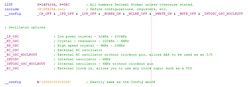
As you can see a word is a lot more concise than a line of symbols although its not clear what your actually doing. These configuration settings can be set in the software too so if left out they will default, I would recommend listing everything as if it's all there in front of you it's easier to diagnose a problem.
Back to oscillator frequency and why it may be important to change it. As you should know in digital circuits when something switches it wastes a little power, the more it switches the more power that is dissipated and lost. So for example if your just experimenting and using the power from the wall outlet then it doesn't really matter how much power you waste as it's minute. If however you are running your project from a battery then a high clock speed will drain the battery faster, if your program can run slower then you may as well do so to save power. For example from the datasheet running at 32kHz will typically use 10uA whereas running at 20MHz will use 2.75mA, that's a huge difference.
One thing to note, when you create delays they can be quite long winded so they are normally saved as a template, it is worth noting that changing the clock will change the delay. If all your ever going to be doing is running your projects from an outlet or something that doesn't require efficiency then it's best to stick with the same value for all your projects. I originally stuck with 4MHz as it was the standard internal frequency although since the chip will run at 20MHz I chose to adopt this by using an external crystal, all projects from here on will be 20MHz. Another thing to also consider is chip memory as high frequencies will need larger nested loops for delays.
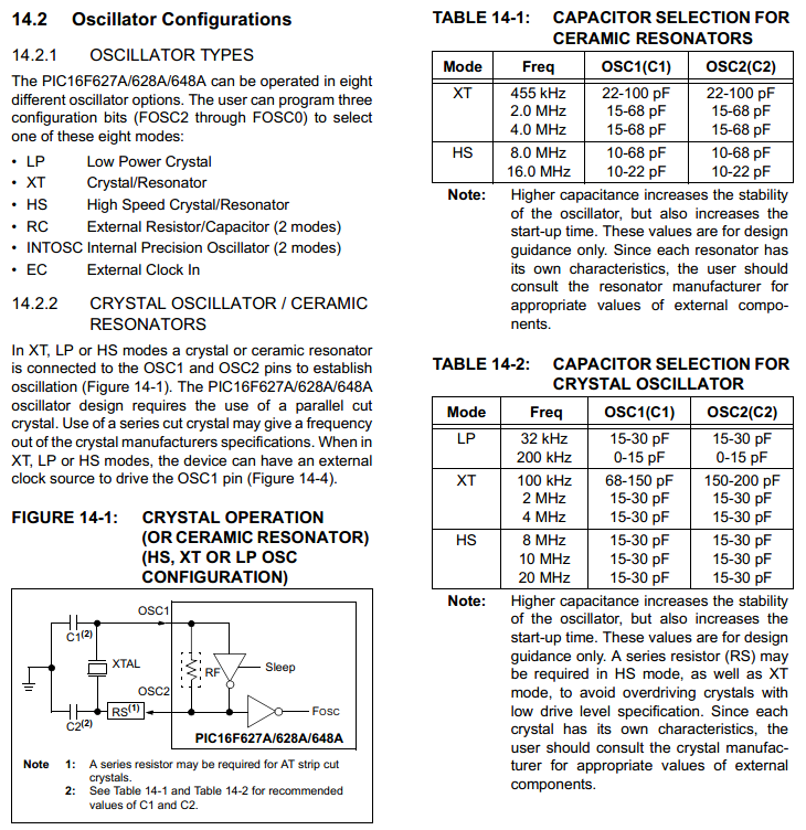
Below is an extract from the datasheet showing the frequency ranges of the modes and what capacitors you will need in conjunction with your crystal. I will be choosing 20MHz so will need capacitors in the range of 15 - 30pf, I chose 22pf as it's a commonly used size. There is a little diagram showing how the crystal and capacitors are connected to the chip, on the datasheet the pins will be labeled as "OSC1" and "OSC2", RA7 and RA6 for this chip.
Now as for the program use the same as that in the flashing LED but this time choose the correct config symbol for the crystal your going to use. I will be using a 20MHz crystal from now on, so I would choose "_HS_OSC" as my config option. Below is the revised program along with a link. - Program
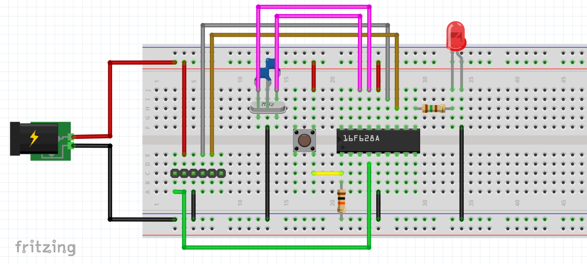
Here is a digital representation of what it should look like on a breadboard, it is sometimes better to choose the low profile crystals as they aren't easily caught and are around the same price.
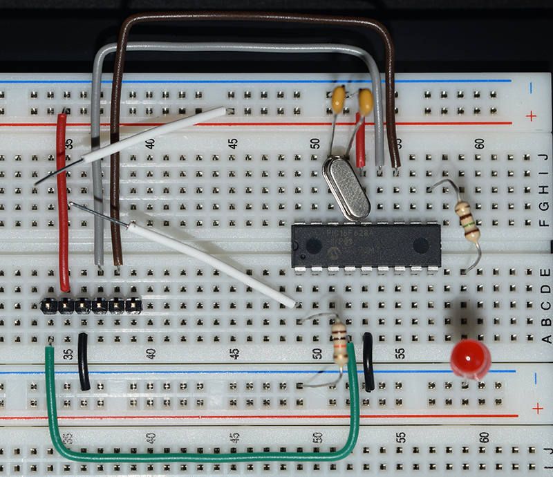
Below is my circuit on a breadboard, careful not to let the capacitor leads touch the metal case of the crystal.
When you program the chip you will notice that the LED now flashes five times faster as you would expect, it may be a good idea to include another nested loop in the delay to slow it down. Now you have got the chip to work and know how to configure it, it's now time to get on with the commands to know how to create a more complicated program, such as to drive an LCD, a keypad input, and much more...
Hello, if you have enjoyed reading this project, have taken an interest in another or want me to progress one further then please consider donating or even sponsoring a small amount every month, for more information on why you may like to help me out then follow the sponsor link to the left. Otherwise you can donate any amount with the link below, thank you!