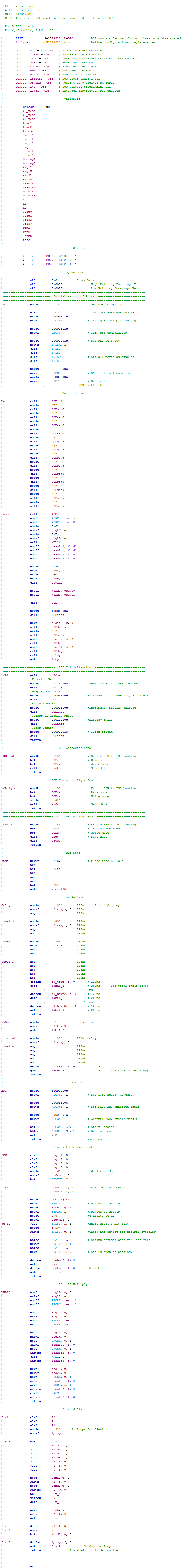
18 Series - Chapter 10 - ADC (Analogue)
Most modern microcontollers will have an ADC module contained within them, analogue to digital converter. It can be quite useful to have the ability to read analogue with a microcontroller but generally I find the 18F4520 quite limiting and that an external converter is sometimes the best option.
Registers
At the end of a section in the datasheet will be a diagram as shown below. All of these are the registers associated with the analogue module, of course there are many that we don't have to worry about.
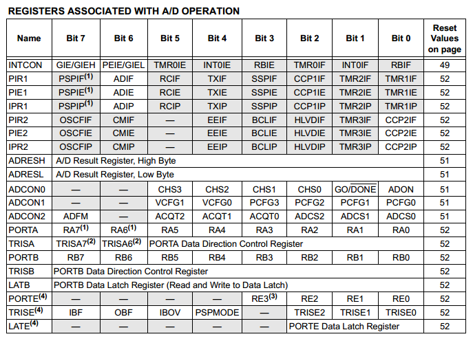
The first seven registers are examples of those we can ignore for now as these are connected with interrupts and this function we are not using.
The next five registers are those we use to configure the module and the data we attain from the reading.
The last eight registers are tied to Ports, of course we need to input some data.
Why ADC Sucks on the 18F4520
In most other microcontrollers there is the option to set particular pins as analogue or digital with the aid of the ANSEL register, however this is not present on the 18 series. Instead is the ADCON1 register that allows us to set AN0 to AN12 as analogue or digital, the issue is the flexibility.
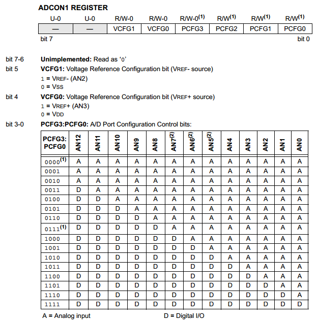
The last four bits of the register are used to configure the pin as either digital or analogue.
The issue is that if I wanted to set AN9 for example as analogue then I must also set everything before it as analogue, it decreases the flexibility of a project and is the reason I prefer an external module.
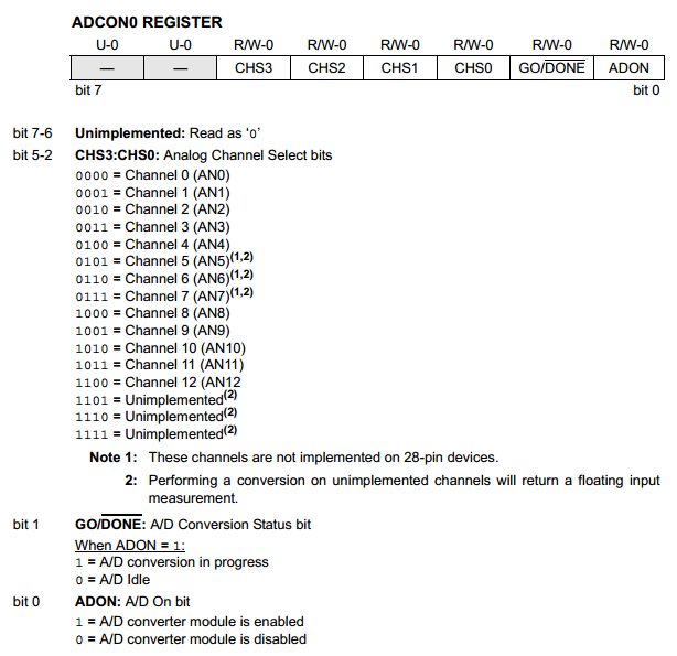
Channel Select
The ADC module can only read one input at a time, each channel must be selected in turn.
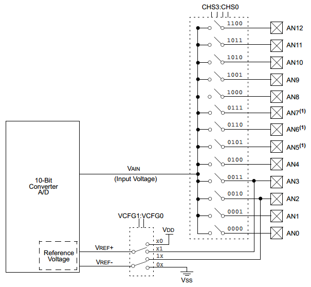
The ADCON0 control register is used to select which channel, bit-1 is used to read the channel. This particular register is used a lot in the reading process as we use it to initiate the read and also select which channel to read from.
Timing Control
The ADCON2 register is one that is to be set in the initialisation stage at the beginning of the program as it does not need to be altered. It controls the speed at which the analogue module runs and how the read data is stored in the two result registers (10-bit). This register is all dependant on the oscillator speed as there is a limit to how fast the module can convert.
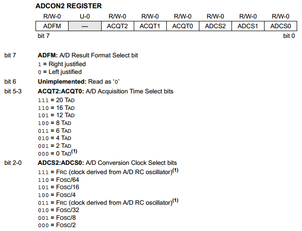
The first part to discuss is the clock source, a table is given in the datasheet which gives guidelines. Since I will be running my microcontroller at 32MHz it concludes that from the table below I will set ADCS as 010b.
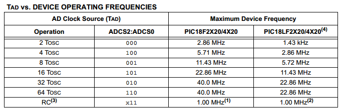
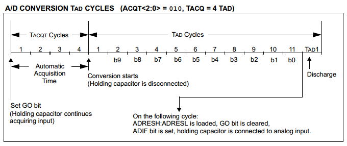
The second part is the acquisition time which acts like a delay. First to discuss is the TAD cycle which is what we set in the above table, so since I have gone for a 32 clock divisor and the clock speed being 32MHz it means that one TAD cycle is 100ns. The analogue conversion process takes a total of 10 TAD cycle since the result is 10 bits long, therefore 1us. The acquisition time is a delay to allow the ADC module capacitor time to charge, the capacitor being 25pF.
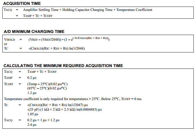
There are a few equations that can be used to calculate the acquisition time such as these below. In general an acquisition time is not required for most applications, it may be necessary for applications with accurate timing.
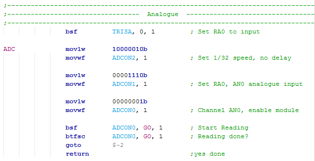
Analogue Read Program
The program is rather simple, the first five lines can be left in the initialisation part at the start of the program if using multiple analogue channels otherwise if only one channel is used such as in the example below then everything can be left at the initialisation at the start, otherwise only the last four lines are required.
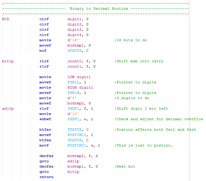
Binary to Decimal Conversion
Once the analogue value has been read we have a 10-bit value, this can't be sent to a display because it doesn't mean anything yet. Lets for example say that the value read was 500, this needs to be split into three numbers "5", "0" and "0". These values then need to be converted to ASCII for the LCD to recognise, simply "48" is added to all of them. This program below will do just this, it works in multiples of 8-bits and can work any amount of digits.
Useful Data
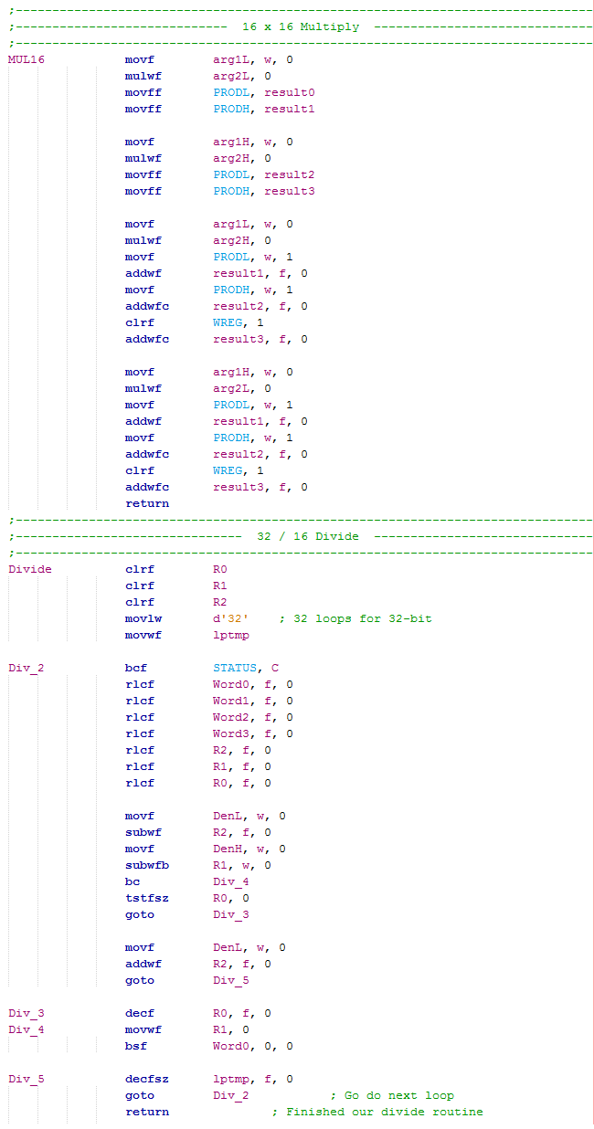
Before converting the read value to decimal it is worth manipulating the data first into something useful. So for example I have read a voltage using ADC and my result is 150 which means very little without further calculation. Since we have 1023 bits for 5V then it is simply (5 / 1023) x read value. So our voltage reading would be about 0.73V. The microcontroller cannot work in decimal points so we do our result multiplied by five divide by 102, or just 10. This way I would get 7 or 75 which is close to the result and we can always add a decimal point in the display. Another way would be to do our result multiplied by 500 divide by 1023 to get the result 73, this is now accurate.
Here is an example of both the multiplication and division programs.
The Main program is as follows.
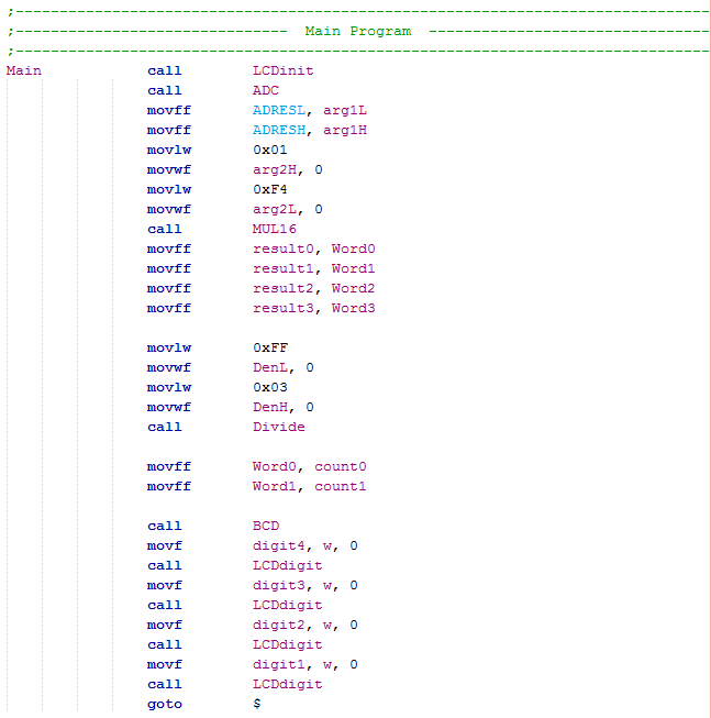
So first the analogue is read and placed as one argument ready for multiplication, the other argument being decimal 500.
The multiplication result is moved to the division variables.
The denominator set at decimal 1023 and then the division commences.
The result of the division is sent to the BCD program to convert it to four digits before displaying all of them to the LCD.
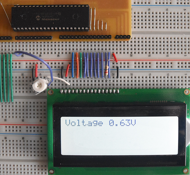
Volt Meter Program
A simple application for reading analogue may be a volt meter, for example I use it to read the voltage for the LCD contrast which was read to be 0.63V in a previous chapter. The following program will do this and here is a - Text Version.
The program working, displaying the contrast voltage on the LCD. The read value is the same as my volt meter showing that the program and microcontroller are accurate.
The ability to read analogue has many uses and this particular microcontroller can handle it very fast, I do however recommend an external ADC chip for ease of use with this microcontroller. The next chapter will discuss asynchronous serial.
Hello, if you have enjoyed reading this project, have taken an interest in another or want me to progress one further then please consider donating or even sponsoring a small amount every month, for more information on why you may like to help me out then follow the sponsor link to the left. Otherwise you can donate any amount with the link below, thank you!