18 Series - Chapter 12 - Interrupts and Timers
The interrupt is one of the most important parts of a microcontroller as it can cause a program jump any time. Each peripheral on the chip will be linked to the interrupt block meaning that something such as an analogue read can be used to interrupt the main program. The best example would be the asynchronous transmit program running at a baud of 9600, to send just one byte will take around 1ms which is a huge delay compared to the running speed of the microcontroller. While the serial is being sent the microcontroller can continue doing something else, the interrupt could be used to detect when the serial has been sent which causes a program jump much like a call command to a section of program to deal with the interrupt, such as send more serial data.
Logic
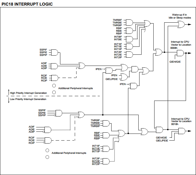
Below is an extract from the datasheet showing how each of the interrupt modules are linked. The important part to note is that each of the AND gates represents some kind of a peripheral such as the serial module, it has three inputs in which each correspond to a bit in three different registers. One register is to enable the interrupt function, one to show the interrupt flag and the other is a priority - high or low.
Control Registers
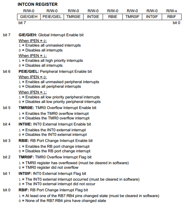
There are four main control registers, it must be noted however that these mostly contain controls for the peripherals. The bit that concerns us the most is the "GIE" bit which turns on the interrupt function and the "PEIE" bit which enables interrupts for peripherals. Each peripheral will have a bit attached to it, one to enable, the flag and the priority. The rest of this register is to configure a change of PortB interrupt and the timer0 interrupt which I will discuss later.
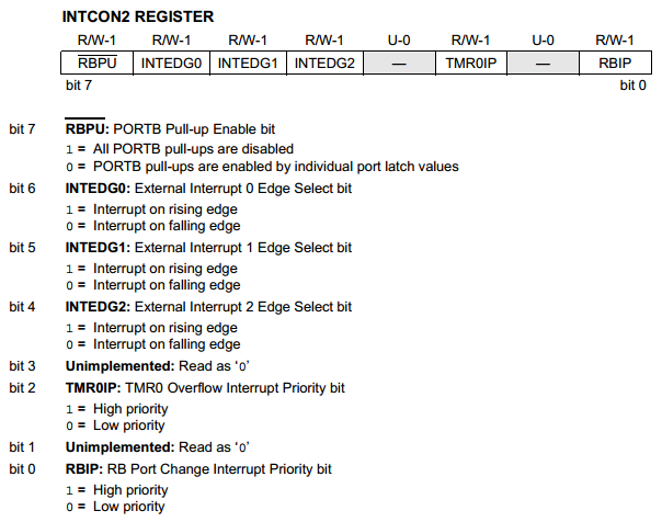
This register is mainly concerning three external interrupts and whether the condition is met on a rising or falling signal. The remaining two bits are to set the priority level of the PortB change and timer0 interrupts.
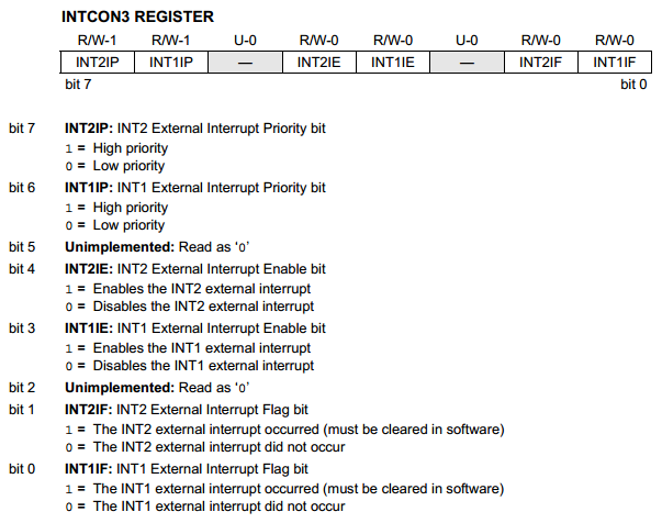
This register is to control the external interrupts, the enable bits, priority bits and the flag bits.
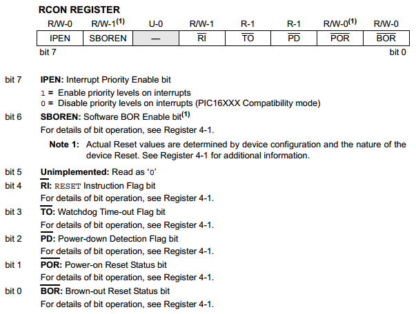
The last control register is the "RCON" which only contains one bit associated with the interrupt function, the rest of these are mostly flag bits and will be of little concern.
Interrupt Registers
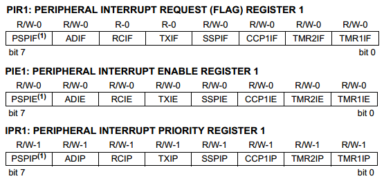
Each interrupt is linked to three registers, the enable, the interrupt flag and priority register. The first example shows how all three are linked and that once you know what each bit is on one register then you don't need to look up the rest of the registers in the datasheet.
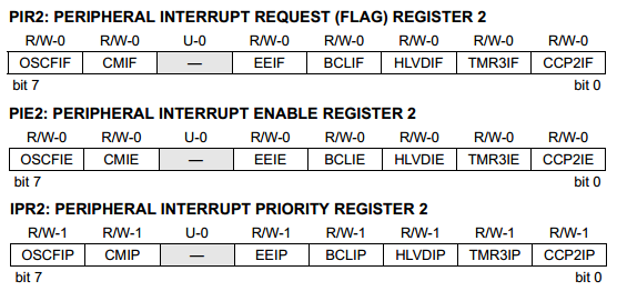
This is the second lot of peripheral interrupt registers.
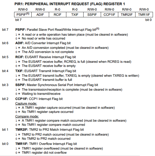
Here is an example of what each bit controls with regards to the peripheral interrupts.
Asynchronous Serial Interrupt
In the previous chapter I showed how the asynchronous module worked, for this little section I will discuss how to use the interrupt function. An interrupt is used for a condition where there is no specific timing, a random timing. The interrupt is mainly used for external sources such as receiving data via serial. The interrupt can also be used internally for slow functions such as the serial transmit since sending 1 byte at 9600 baud will take approximately 1ms. The data is set to send, once sent the interrupt condition will occur telling the microcontroller it is ready to send more data.
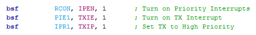
The first step is to set up the interrupt and whether we need it to be low or high priority, for this example it simply doesn't matter. The difference in choosing between priorities is where the program will jump to when the interrupt condition is met, remember an interrupt causes a jump to either location 0x008 or 0x018. This example below turns on the serial transmit interrupt and sets it to high priority.
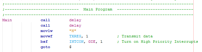
This is the main program that delays for two seconds to allow the serial LCD time to initialise and then it sends the character "H" to the serial LCD. The high priority interrupts are turned on and then when the data has been sent will the interrupt bit flag and cause a jump.
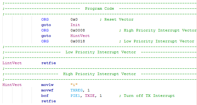
The program jumps to the high priority vector location 0x008 which then jumps to a section of program to deal with the interrupt. On this occasion I choose to send the character "i" and then disable the interrupt function. To return from an interrupt the "retfie" command must be used.
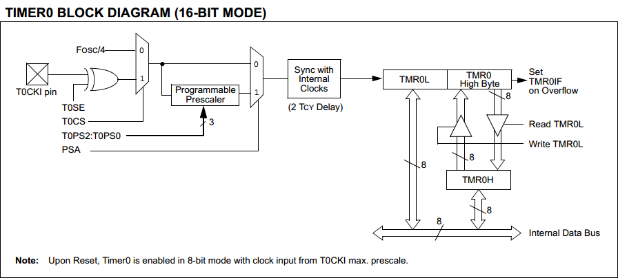
Timers
The timer is one of the single most important parts of the microcontroller. A microcontroller will generally contain many timer modules, for example the 18F4520 contains four. For ease I will only discuss the timer 0 module in this section. Below is a block diagram of the timer 0 module, note that it can run in 8-bit or 16-bit mode and that I have chosen 16-bit mode for this example. All a timer does is count, it contains at least one register, two in this case, that can be written to. When the timer is activated it counts up at a speed dependant on the clock and a prescaler, when the register overflows it will flag an interrupt condition. So for example I could be in 8 bit mode and each count is 10ms, I set the register to 155, after 100 counts it overflows at 255 and 1 second has passed, the interrupt flags and then I can deal with the outcome.
The TMR0H register is only written to when the TMR0L is written to, much like the PCL to allow all data to be moved at once.
For this module there is only one control register.
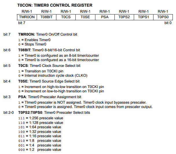
bit-7 - TMR0ON - Starts or stops the timer module counting.
bit-6 - T08BIT - Count with the TMR0L register in 8-bit mode or count with TMR0L:TMR0H registers in 16-bit mode, the second option allows more timing flexibility.
bit-5 - T0CS - Internal or external clock, this allows a much more accurate external timing source or an odd timing frequency to be used.
bit-4 - T0SE - Is the timer clock on a rising or falling edge, this is for the external clock source.
bit-3 - PSA - Allows the use of a prescaler, this is needed if you want reasonable delays.
bit-2 t0 0 - T0PS2:T0PS0 - The prescaling selector bits, these act like a clock divisor.
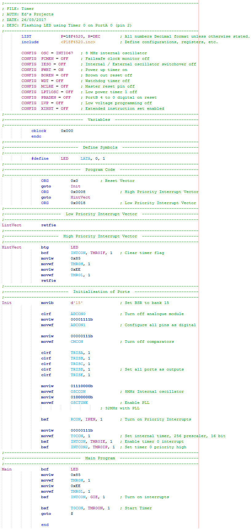
The example I will give is a flashing LED using Timer0 and interrupts. Firstly remember that the clock speed has been set to 32MHz and that by choosing the internal clock source will give us a divisor of four according to the block diagram. Combined with setting the prescaler at b111 / 256 will give each count the duration of ((1 / 32M) x 4) x 256 = 32us. One second divide by 32us gives us 31250 counts. So TMR0L:TMR0H must be set to 65536 - 31250 = 34286. So by setting the registers to 34286, after 31250 counts will give us 1 second and then the interrupt flag. One thing to note with all interrupts is that the flag must be cleared. Here is a copy of the program - Program Text.
The interrupt and the timer are very important functions for a microcontroller, these are the two modules that you will likely use in all projects. The next chapter will discuss SPI which is another form of serial communication and the external memory chips such as SRAM and FRAM.
Hello, if you have enjoyed reading this project, have taken an interest in another or want me to progress one further then please consider donating or even sponsoring a small amount every month, for more information on why you may like to help me out then follow the sponsor link to the left. Otherwise you can donate any amount with the link below, thank you!