18 Series - Chapter 14 - SD Card Part 1
The SD card is a great asset to the microcontroller project due to the size of the data it can store, for me the most important part is that I can load data onto it from my computer. In part 1 of this section I will show how the SD card works in terms of hardware, how to initialise it and how to read and write data. In part 2 I will show the file structure and how you can load images and text documents.
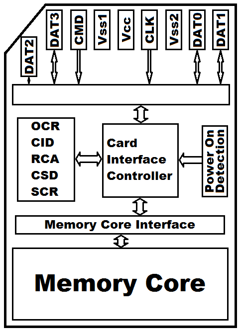
Here is a diagram of the common SD card.
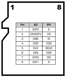
You may come across two different types of card, the SD and the MMC. They are both the same size except the MMC card does not have a DAT1 or DAT2 tab. DAT3 is used as a reset, all of the other pins are the same.
DAT0 serves as the SPI data pin. MMC can only run serial whereas the SD can also run "SD BUS" which uses four data pins to send / receive data, we will not be using that function.
Both cards can indeed be used for this project however their data structure is a little different, I will be focusing on the SD card as the MMC is rarely seen.
All SD cards will have the same structure as that in the diagram to the left, the only exception will be the size of the memory core.
The OCR, CID, RCA, CSD and SCR are all different types of status registers, these are normally only needed in the initialisation process and can normally be ignored thereafter.
The memory core in an SD card is made up of 512byte blocks, a single byte cannot be read. The MMC card however works on byte by byte which makes it useful for external RAM buffers. The addressing system is 32 byte on both cards which means that a theoretical total of 2TB for the SD card and 4GB for the MMC card. 4GB for the MMC is still probably way more than we will ever need but simply these cards are obsolete in the modern world, most stores don't stock them anymore.
I will be choosing the micro SD since it was much cheaper for me to buy this and an adapter than a full size SD, not quite sure why.
The only difference between the micro SD and the SD is the lack of a second voltage supply pin, they are both limited to 3.3V, I'm not entirely sure why the SD has two supply pins.
SPI Commands
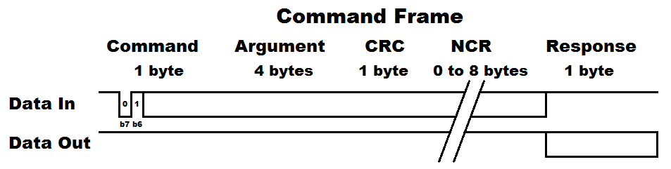
I will be running the SD card in SPI mode, the commands have a certain protocol that must be followed. For this project I will only be showing the commands required to initialised, read and write. Firstly the protocol. The commands always have bit 6 set, or decimal 64 added, so for example command 0 would be 64, command 2 would be 65, etc... The argument is our address we want to read or write to. The CRC is a checksum, it does not need to be valid for SPI commands but it must be present. NCR is the processing time of a command before a response is given, the NCR is continuously sent until the response is received. There is one main response (R1) which tells us of any errors, there is another response (R3) which is an extra 4 bytes after the R1 telling us a status register such as the OCR.
There are two main types of SD card, the SDSC and the SDHC (Standard capacity and high capacity). It is quite rare to find a standard SD card as they are now almost all exclusively SDHC. There are a couple of different commands attributed to each type of card, I will only be discussing the required commands to initialise, read and write to an SDHC card.
| Command | Argument | Response | Data | Description |
|---|---|---|---|---|
| CMD0 | None / Zero | R1 |
No |
Software reset |
| ACMD41 | Zero | R1 |
No |
Initialise SDHC |
| CM8 | 000001AA | R7 |
No |
Check card type / voltage |
| CMD12 | None / Zero | R1 |
No |
Stop reading data |
| CMD16 | Block length [31:00] | R1 |
No |
Set read / write block length |
| CMD17 | Address [31:00] | R1 |
Yes |
Single block read |
| CMD18 | Address [31:00] | R1 |
Yes |
Multiple block read |
| ACMD23 | Block quantity [22:00] | R1 |
No |
Set number of blocks to erase |
| CMD24 | Address [31:00] | R1 |
Yes |
Single block write |
| CMD25 | Address [31:00] | R1 |
Yes |
Multiple block write |
| CMD55 | None / Zero | R1 |
No |
Sent after a ACMD command |
| CMD58 | None / Zero | R3 |
No |
Read OCR |
It should be noted that the above commands are valid for SDSC, command 16 is however not valid for the SDHC. Command 16 is known as the block length, so for a SDHC this is 512 bytes and cannot be changed. The SDSC can be raised to 1024 bytes per block if required, I however would not recommend doing so.
The Responses
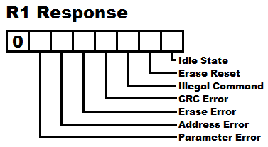
The R1 response is a very simple one and used in all of the commands, basically we want this byte to be clear.
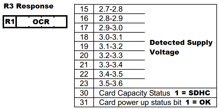
The R3 response is a product of the R1 response. It is really only going to be bit's 30 and 31 to be checked, some bits display the supply voltage and the remaining bits are reserved.
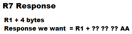
The R7 Response again is a product of the R1 response, it gives very similar information back compared to R3. All we need to ensure is that the last byte is equal to AA, that's it.
SD Card Initialisation
There is a specific procedure for initialising an SD card into SPI mode.
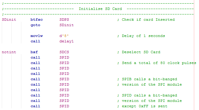
All SD card slots will have a switch in the back to say when a card has been inserted.
A common misconception is that the SD card must be set to 100kHz clock speed, this is only the case with the slower MMC and possibly some SD's, not the case with the SDHC's.
The pins should be touching their contacts when the switch is actuated, the one second is just a precaution.
The cards select pin must be pulled high which deselects the card. At least 76 pulses must be made to the clock in order for the SD to initialise itself, they have no internal clocking source.
It doesn't matter how many pulses are applied after this as the card has not been selected.
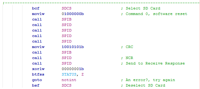
Command 0 is a software reset which puts the SD card into an idle state, once in this state it can be setup to run in SPI mode.
The argument is zero / can be ignored, 0xFF is common to send.
Before we reach SPI mode we need a valid checksum.
The next byte is the NCR, there is only one for command 0.
Another dummy byte sent to receive our response.
The only response we want is an indicator that we have reached idle mode, if there is any other result than one the program resets to the very beginning of the initialisation process.
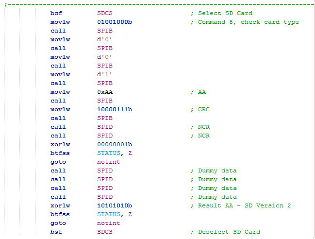
Command 8 is to check we are using the correct card, if not this particular program will keep looping back to the beginning. This part of the initialisation procedure is required, I'm not entirely sure why. The benefit is that you can check you're using the right card, of course the program may not get this far if the clock was not reduced to 100kHz.
The argument must be (in hex) 000001AA followed by a correct checksum value.
Again only one NCR is needed before we read our response, we are still required to be in the idle state before proceeding, if there are any errors then we begin at the very beginning.
After the R1 response we receive the R7 response, all you need to know is that the final byte to be received must be (hex) AA which tells us that SD card version 2 has been recognised, which is a SDHC, anything else then we start from the very beginning.
Command ACMD41 will finally place the SD card into SPI mode.
For this command it does not need a valid argument.
Neither do we need a valid checksum as this command is telling us to go into SPI mode.
Again only one NCR byte is required.
On the first pass the idle flag will still be set, when it is clear the initialisation process is complete.
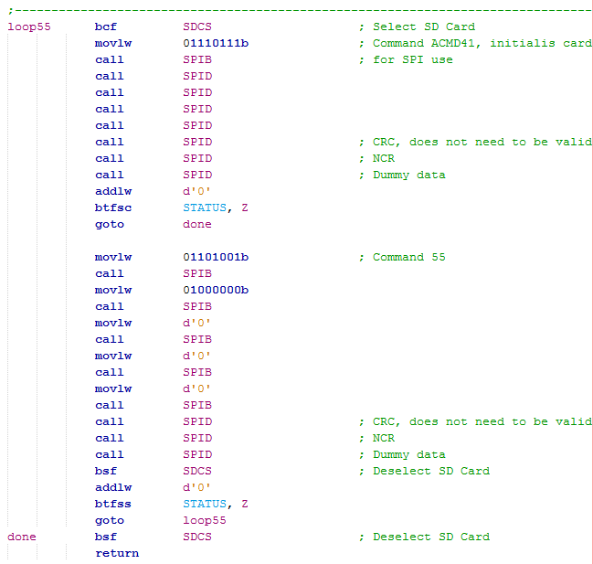
If not then command 55 will be issued, the strange thing about ACMD commands is they are all followed by command 55.
The argument is (hex) 40000000.
No valid checksum is required.
Only one NCR is required.
If the R1 response is clear we skip to the next part of the program, if not then we repeat from command ACMD41.
Note: CRC's, NCR's or zero arguments are generally sent as 0xFF. The reason the data is left high is because this is the way that the SD card works, if the SD card is busy then it's data output pin will be low, when it is ready the data output pin will be high, this is very useful when writing to the card, it means we don't have to send commands to read status registers.
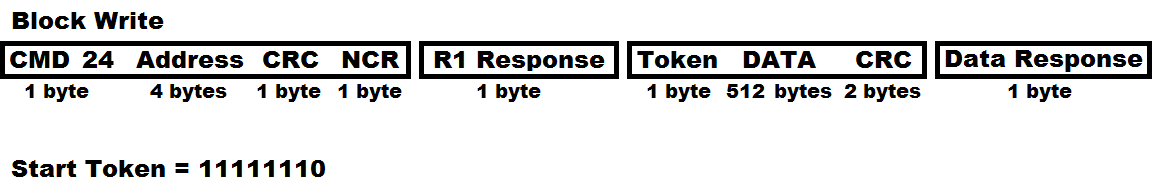
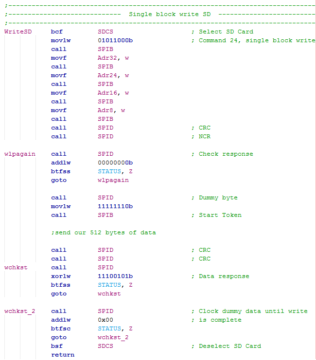
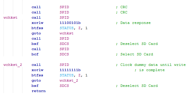
Single Block Write
The first useful command to use would be a single block write, there is the option of a multiple but I will not cover it in this chapter, you should be able to read between the lines. The command to issue in this case would be 24, dummy bytes are then sent until a clear R1 response is received, a further dummy byte and then the token byte (11111110b) is sent, the 512 bytes of data are sent followed by two CRC's (don't need to be valid), finally a data response is received to say if the data was successful, dummy data is continuously sent until the correct response is received indicating the write has completed, this would be receiving any data apart from zero. No erase command for the SD, it is done by itself in hardware.
Here is an example of a program.
After the data response has been received the SD card is ready to write, in order to do this the SD card has to be de-asserted, clocked eight times (1 byte) and then reasserted before the status can be checked. The above section of program may sometimes work and it is often how datasheets are to be interpreted, however for the correct procedure the SD card has to be deselected to initiate it's write sequence.
When the SD card is busy it will pull it's data output low (only when it has been selected), when it pulls high it means that it is ready. The program below is an alternative method to that above, while they both achieve the same thing we are ideally looking for 0xFF, this is the correct procedure.
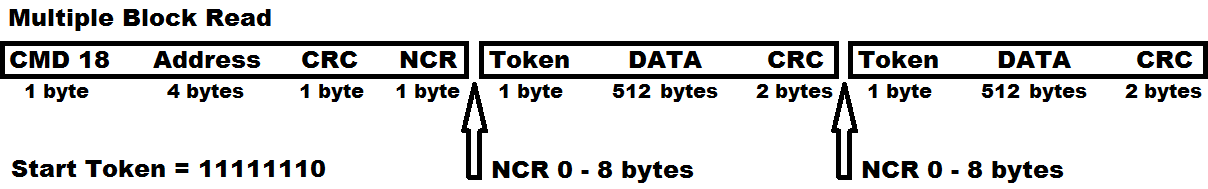
Multiple Block Read
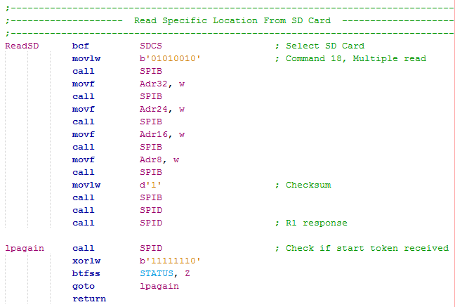
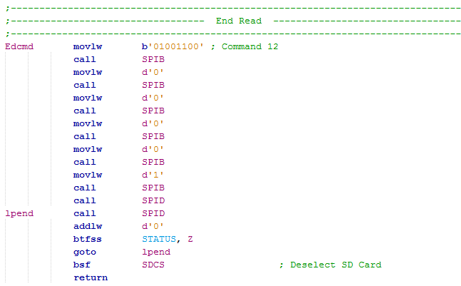
Command 18 is the multiple block read command, there is no point explaining the single read command. The command is sent like any other except the argument is the address of the block that we want to read from, since we're in SPI mode the CRC does not need to be valid. An NCR is sent until a start token is received, the next 512 bytes after that will be the data and then two CRC bytes. Multiple NCR's need to be sent again until the start token is received to read the next block. At the end of all this there must be a command 12 which will stop the read process.
Here is an example of the read program.
Here is an example of the end command, there will be a number of NCR's so the program loops until the R1 response has no errors.
As you can see the process of initialising an SD card is pretty simple, and so is reading and writing to the card. The next chapter will explain how the data is to be stored in the SD, the file structure and how the addressing system works.
Hello, if you have enjoyed reading this project, have taken an interest in another or want me to progress one further then please consider donating or even sponsoring a small amount every month, for more information on why you may like to help me out then follow the sponsor link to the left. Otherwise you can donate any amount with the link below, thank you!