18 Series - Chapter 2 - Software, Hardware, Configuration
This will be quite a large section explaining how to use the software, what hardware is required and how the chip is to be configured in order for it to function properly. A lot of the content will be very similar to the 16 series section, I have not copied it however as I have chosen to write it from scratch along with the rest of these chapters.
Software
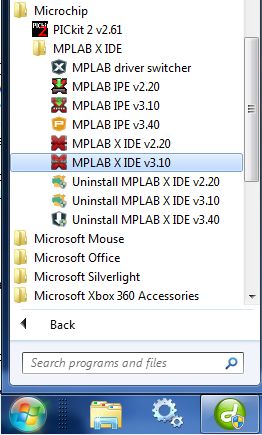
The software I will always use is MPLAB X IDE since it performs perfectly and allows the user to use a variety of programming languages, the version I currently have is V3.1 which at the time of writing this is the newest version. The best part is that this software is free and will pretty much run on anything.
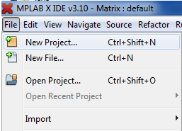
The first step is to create a new project by clicking "File" and then "New Project".
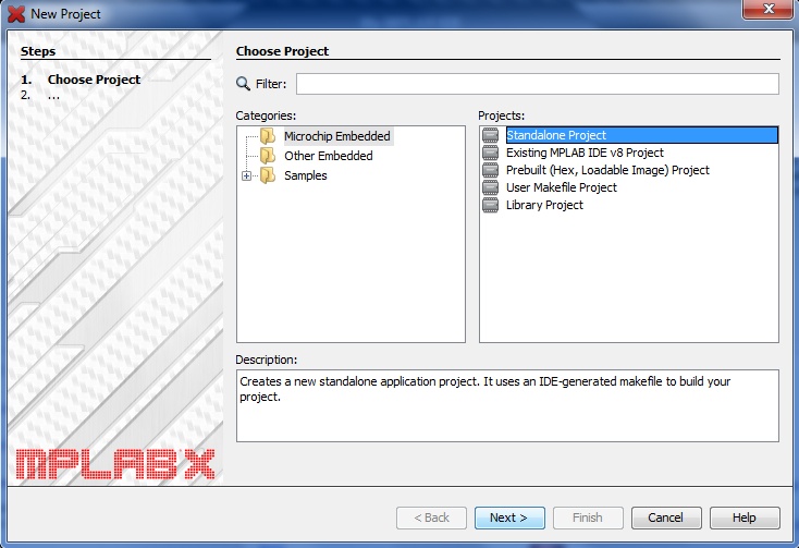
Choose "Standalone Project".
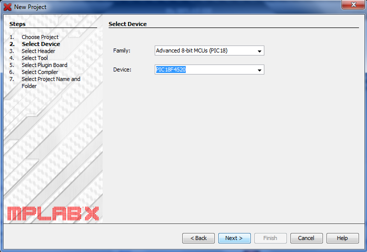
Select "Advanced 8-bit MCU's" and then find the PIC device you want, ideally you should choose the same as me or something very similar in the 18 series.
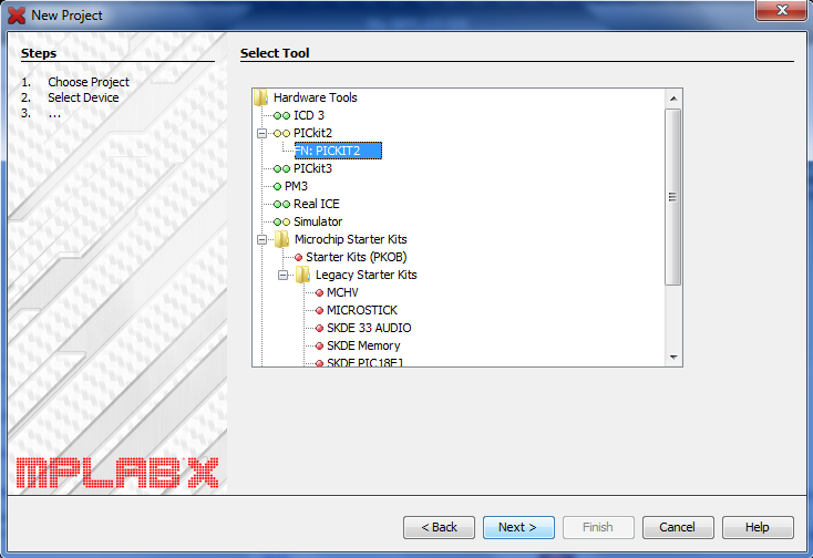
This will be explained a little further in the hardware section but you will need a programmer, for me I chose "Pickit 2" which is the cheapest that Microchip offer and it is capable of programming anything in their range. If you are just playing with the software then you should choose the "simulator" option, it will still allow you to check bugs in the program later on.
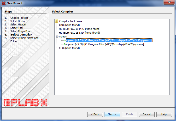
Choose your compiler, again this will all depend on the programming language you wish to use however I will only be using assembly for all of my projects and therefore have chosen "mpasm".
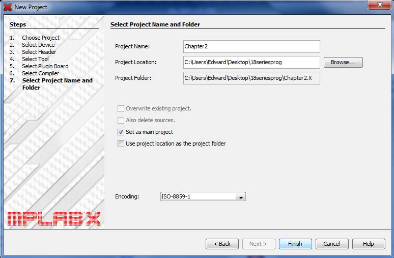
Give your project a name and choose an appropriate folder to place it in.
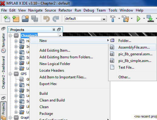
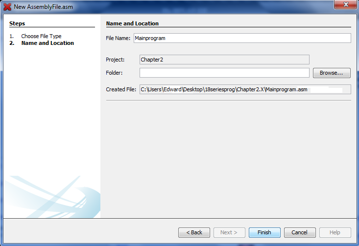
Since I will be using assembly to program my chip I must choose to create an assembly file by right clicking on my project and then "New" and "AssemblyFile.asm".
Choose an appropriate name, I would always go for the project name or something generic like "MainProgram".
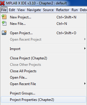
Next click on "File" and then "Project Properties".
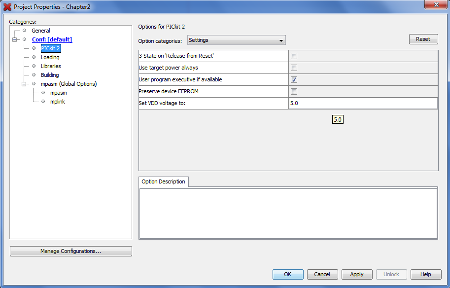
Click on your programmer as we need to set the programming voltage. It should be by default 5V but it is always a good idea to ensure it is, you may also need to change it to 3.3V for some projects. The reason for doing this is because I will be using the programmer to power most of the projects in these chapters.
That's it for the software in this chapter, in further chapters I will show you how to debug a program in simulation.
Hardware
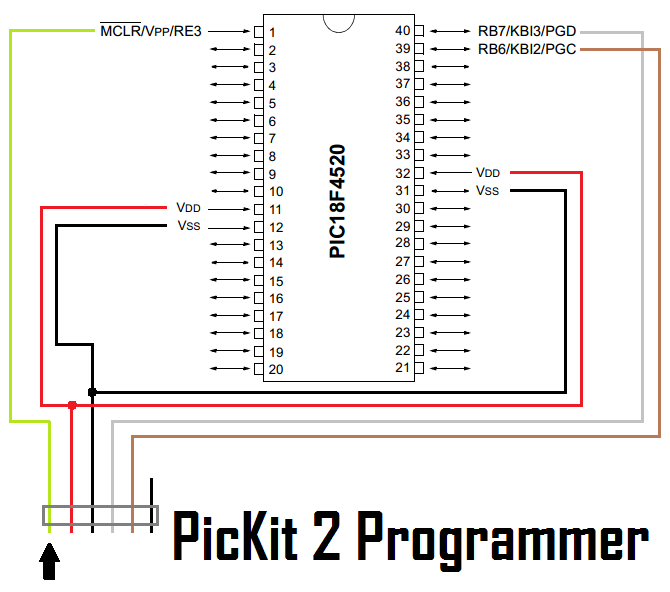
I would really recommend the PicKit 2 that Microchip sells itself as it is the cheapest programmer but is capable of programming their whole series of chips. Here is the circuit diagram connecting the programmer to the chip. The MCLR pin is to reset the chip in order for it to be programmed, PGC is the programming clock and PGD is the programming data.
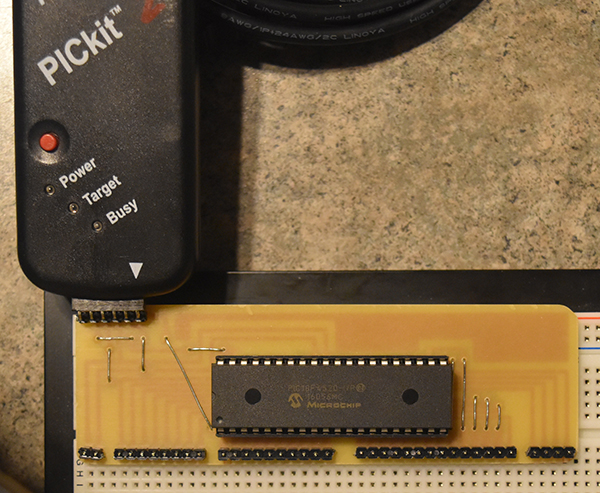
Here is a little breakout board I made for the chip as placing a header in the circuit can be messy, a breakout board also places all of the pins in one row making it easier by having no jumpers crossing over the chip. I would always recommend a programming board to hold the chip as the chip can always be removed if necessary to be placed in the application, breadboard programming can sometimes be problematic. This particular board I have made will allow me to program as normal, if I need to program the chip away from my circuit then I can lift the breakout board from my breadboard. It must also be noted that external components connected where the chip is programmed may cause issues, the breakout board can be lifted to program under these circumstances.
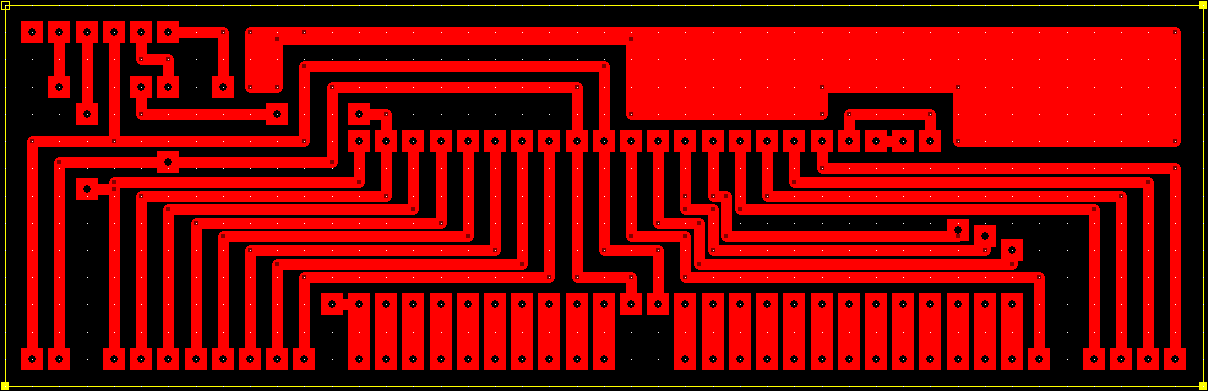
Here is the copper track layout, I have placed a few jumpers in order to bunch some of the ports together such as port D.
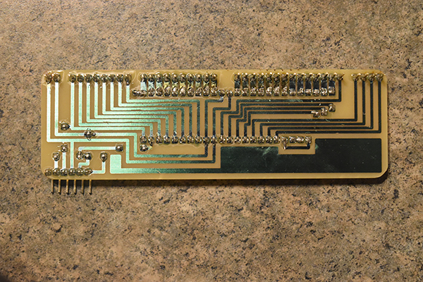
The bottom and top of the board. If you would like to know how I design and make my boards then there is a link under the electronics section in projects.

The hardware part should be very simple to construct, I would recommend building a programming board however it will work just fine on a breadboard.
Configuration
This is the single most important part of the program as this will tell the chip what clock source to use, power up conditions and additional special features. It is quite often the most cryptic part of a program as people don't explain what each section is doing, it is always best to annotate each and every step of a program to make debugging a lot easier.
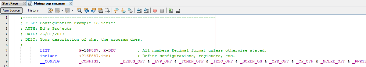
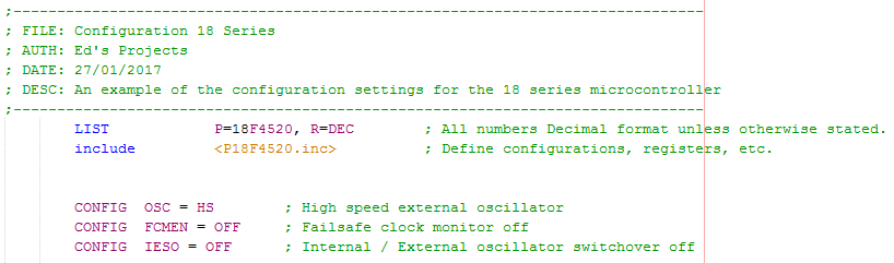
If you have read a program you may get something like the following which I have extracted from one of my programs. The first thing is to write a title of the program that's relative to what your doing, so for example I may have written "GPS Project". It's your choice whether you sign and date the project but it's always a good idea. A description of what the program does, I have on many occasions explained what the program does in great detail and what the function of each pin is.
LIST is known as the "list directive" which helps the software determine what chip we are using, without this it would not recognise special function registers and not allow us to program the chip. The "include" has a very similar function but this is a link to a file that contains all the special function register locations in the chip and any other required information in order to program the chip. The "config" section is the most important and unfortunately can become quite cryptic in the 18 series if not written in the "standard" way, this may apply if you're debugging someone elses program.
To make sense of all of the rest of this chapter and all of the following chapters it is crucial that you know what a register is and what it does, fortunately we have large datasheets telling us what each register does. The best way to describe a register is a row of switches which can range anywhere from 2 up to 64 or more (64 bit or more). Since our microcontroller is 8-bit we will have an 8-bit register, it is quite possible however that the registers can be higher such as 16-bit, in fact one of the 16 series chips known as the 16F628A has a 14-bit configuration register.
For now we will call the definition of a register to be 8-bit which is standard practice in all 8-bit microcontrollers, a 16-bit register for 16-bit microcontroller and so on. The same is for my computer, it will contain a huge list of 64-bit registries, I would not recommend playing with them. Below is an example of an 8-bit register from the Special Function Registers, it is known as PORTB or in location F81h in the SRAM. In basics a register is similar to a set of switches as each bit can be a 1 or a 0, on or off. For this register each switch will react to a specific pin on the chip, or more accurately these correspond to inputs so will be a 1 at +V and 0 at 0V.
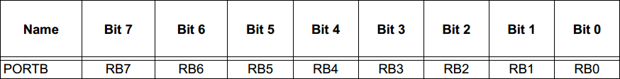
A register can also be used for the configuration aspects of a port, so for example TRISB would control whether Port B are inputs are outputs. Then for example PORTB will read the inputs and LATB will control outputs. The purpose of TRISB is to control which pins are controlled by LATB register and which are controlled by the PORTB register. So a register just contains data whether it's input, output or configuration data. There are a special set of configuration registers not placed in the SRAM but another special location in the chip, these are set at the start of the program and normally left alone however they can still be accessed when the chip is running if required.
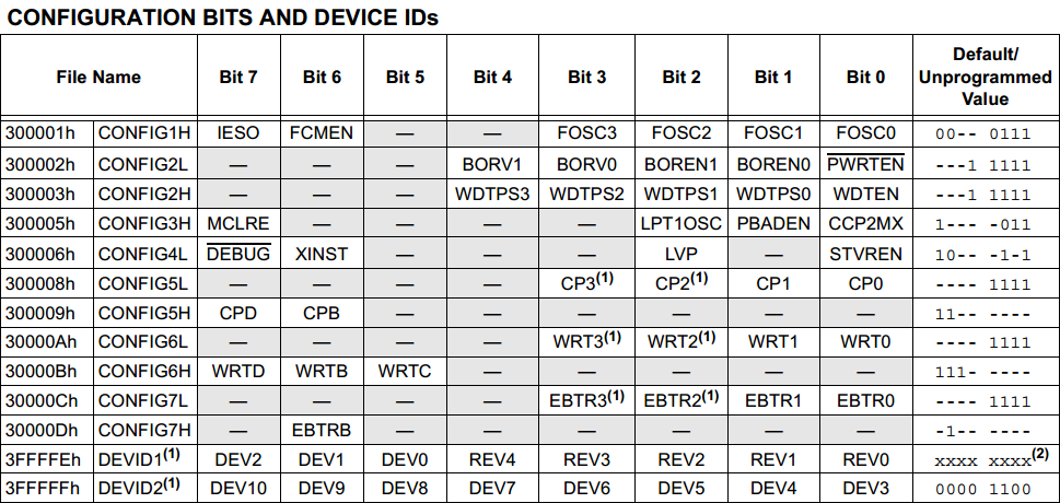
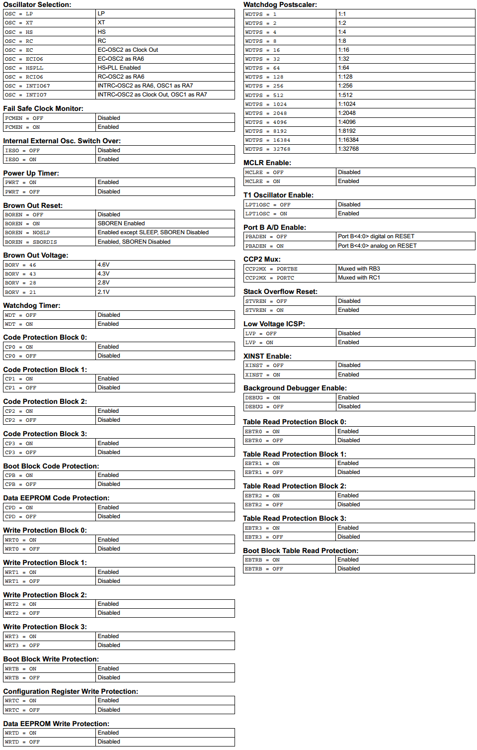
The little snippet of program I showed earlier showed just one of two configuration settings for the 16 series 16F887 chip. For the 18 series there are a lot more settings as shown below. The main purpose of a datasheet is to tell us what each of these registers control and since there are a total of thirteen configuration registers there will be a further thirteen pages to explain their purposes. It must also be noted that it is not necessary to include configuration settings at the start of a program since they will default but it is advisable to do so.
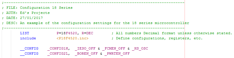
Here is an example of how the configurations settings may be written, those we want to change will be included in the program and those we don't can be left out to default. A quick read of the program you may be able to link most of the information to the registers but you may wonder what "_HS_OSC" means. The "FOSC" parts are to control the clock source and oscillator speed, using "_HS_OSC" is a short cut to specifying which oscillator configuration we want, these kinds of short cuts are picked up with experience but there is a different option.
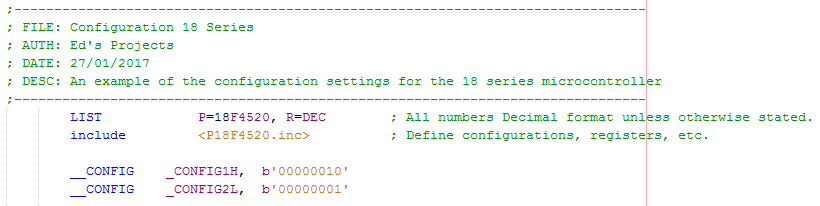
The other option is to specify the configuration settings in binary, this makes a little more sense since our registers are in binary.
I always preferred the method above but the previous two are outdated, it is likely that the software will warn you that these are obsolete. The following method makes much more sense to say a programmer than it would if they were a set of binary numbers, the point of using symbols like this is to stray away from using datasheets all the time, any programmer will know what these mean.
There is a datasheet in my "PDF's" page called the "PIC18 Configuration Settings Addendum" which tells you all of the symbols for the configuration settings. Here is an extract from the datasheet for my particular chip, the 18F4520. Most of this will make little sense for now, the important parts I will explain in the remainder of this chapter and the parts I skip will likely be a chapter in their own right.
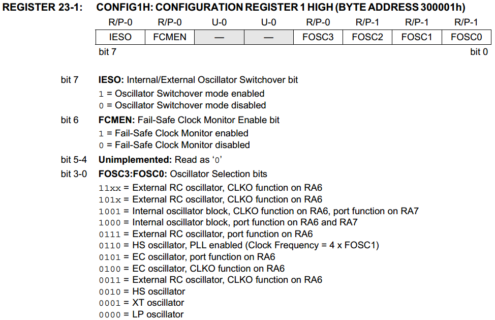
Since I will be working in symbols for the configuration I won't need to refer to the datasheet for the registers definitions, however for practice I will show you what a datasheet will tell you in regards to registers. So for example this is the first register for the configuration settings and is made up of 8-bits, like all of the registers. Each of these bits will represent a particular setting, so for example bit7 controls an internal / external oscillator switch over. Bit6 controls a fail safe clock monitor and bits 5 and 4 don't matter. The remaining four bits control the oscillator source, since we want to choose "HS" we would set bits 3 to 0 at b'0010'. So overall if we wanted to disable both IESO, FCMEN and set the oscillator source to HS then we would set the register as b'00000010'.
The next step in this chapter is to explain what all of our configuration settings do, some of them I will briefly explain as I will dedicate a chapter to them later on.
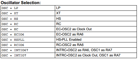
This is the single most important part of the configuration as it specifies what oscillator source we will use, internal or external. It is also important to match LP, XT, HS with the oscillator speed to allow the microcontroller to run properly.
If I were to choose an external oscillator of 40MHz then I would choose the HS option. Since I want to use the internal oscillator option I will choose INTIO67, this will use the internal 8MHz resonator and allow RA6 and RA7 to be used as regular IO pins, an external oscillator would have required these pins otherwise.
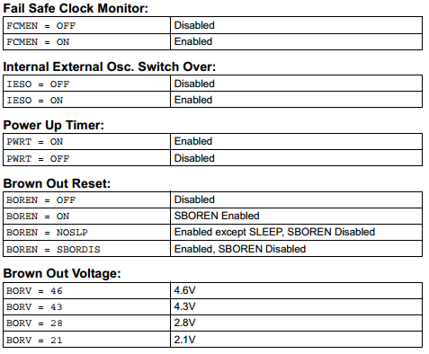
These two functions detect whether the external source fails, it will then switch over to an internal source if required. This type of fail safe is used in medical applications, it is almost never going to be required in your project as oscillator failures are unlikely and your project probably used an external oscillator because it required speed.
When powered up the chip will hold in reset mode for the supply to stabilise.
When the supply voltage falls under a certain threshold the chip will hold in reset.
This is that threshold voltage, since around 4.6V is the minimum required voltage for this microcontroller it would be unwise to go lower. I would normally leave the brown out reset left off.
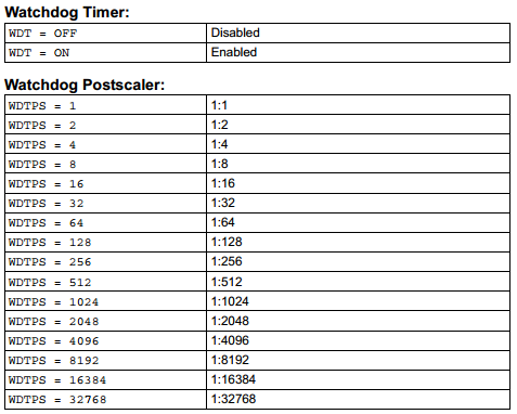
The watchdog timer is a chip reset and a timer, when it counts to a certain value it will reset the microcontroller. A special command has to be issued to reset the watchdog timer periodically, the purpose of the timer is to ensure a program does not get stuck. I have never needed to use such a thing because a program only gets stuck due to poor design. It could however be used due to external events but that is all dependant on your application.
There is a post-scaler used to increase the time that the timer will count to before it resets, it is like a multiplier. I will discuss timers in a different section as there are quite a few different kinds and they are very useful, I would choose to disable the watchdog.
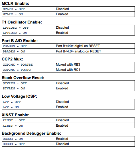
This is to control the master reset pin on the chip, I would disable to gain the use of the extra pin if required.
This is a low power option for one of the timing registers, this is not important for now so I would choose to disable it.
This concerns some pins on PortB setting them as analogue or digital on reset, this is done alternatively in the program when required so I would always choose to disable.
This allows a multiplexing condition to one of two pins, this is no concern for now and it can be left out of the configuration.
This is a reset condition if we exceed our 31 levels of stack, for example we call far too many subroutines, a good program design should never come to this, this can be left out of configuration as it doesn't matter for now.
Always disable, this will allow a low-voltage programming mode on one of the pins, it may cause erratic behaviour so disable it.
This is to enable an extended instruction set, it is worth enabling even if you don't choose to use any of them.
This is only required if you have a debugger and you want to monitor your microcontroller as it's running, you should disable.
All of the other configuration registers I have not discussed are to prevent parts of the memory being either read or written, there is the choice of both. You must be very careful playing with these sections as you can render your microcontroller to be inprogrammable.
I think I have managed to cover all of the aspects of what is required to program a microcontroller, here is an example of a program you can use to test your programmer to make sure it all works. You will need to place an LED, 330 ohm resistor between PortA0 which is pin 2 on the microcontroller to the ground pin. This is just a test so I will explain how it works in the next chapter, below is a picture of the full program or a link to the text version is here - Program Text.
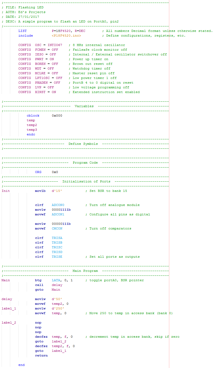
The first of these chapters may be a little difficult to follow at first but microcontrollers aren't really that difficult once you understand how they work. This chapter should have taught you how to start a program in the software, the hardware required, what the configuration settings briefly mean and a simple program to prove you've got it all working. Of course if you have any questions feel free to ask, again I may not have the time to write you programs. The next chapter will get into the programming side and explain what it all means.
Hello, if you have enjoyed reading this project, have taken an interest in another or want me to progress one further then please consider donating or even sponsoring a small amount every month, for more information on why you may like to help me out then follow the sponsor link to the left. Otherwise you can donate any amount with the link below, thank you!