18 Series - Chapter 3 - Flashing LED
The instructions are what our programs are built up of, they determine how data is to be manipulated. With the 18 series of microcontroller there about 75 instructions (83 with the extended set) compared to the 35 found in the 16 series. So firstly I need to explain what an instruction is and what it does. The basics of an instruction is to move data, modify it or just check it with the exception of the NOP (No operation) command which simply just wastes time.
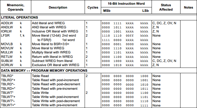
There will be a section in the datasheet which tells you what an instruction does, the registers it affects and how many cycles it will take up. Each set of instructions will have a sub heading of either "Byte", "Bit", "Control", "Literal" and "Memory" operations. Here are three extracts taken from the 18F4520 datasheet, these are all of the instructions.

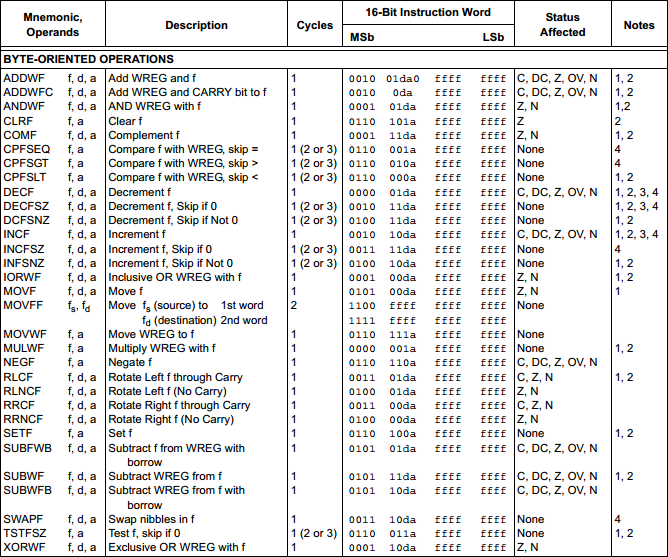
Below is a small extract from the byte-oriented instructions, these will affect 8-bit registers. The first instruction "ADDWF" will add the working register to a file register, the working register is like a bucket that holds the data we transfer and the file register is either RAM or our SFR's. This first instruction is known as a "word" instruction since it requires 16-bit, all of our instructions are at least 16-bit whereas some are 32-bit, a double word instruction such as "MOVFF" which will move one file register to a different location.
The information here is all we need, there are examples in the datasheet however that shows us how to use them. Lets concentrate on ADDWF. The operand is stated as ADDWF f, d, a. Our "f" is the file register in question, "d" is our destination and "a" is our bank location. In the example below "temp" is our file register, it can be a variable in the example or an SFR such as PORTA. The destination is where our final result will be placed, it can either go back in the working register or into the file register. The bank location is either our access bank or the BSR bank, this allows us to keep bank 15 in the BSR to deal with SFR's and switch to the access bank in 0 without having to swap banks first via the BSR.
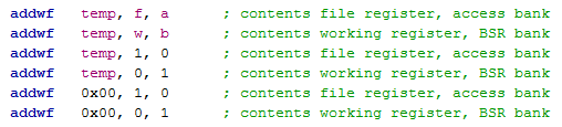
There are two options with writing out an instruction, the "temp, f, a" part can either be in text or it can be in Hex "0x000, 1, 0" which is the same but a little more confusing. It is preferred to use text as we know the file register we are dealing with, where the result will be placed and in what bank. Below are a few examples of how the command may be written.
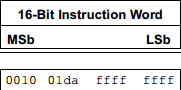
If we take a closer look at our instruction we will notice that it is 16-bit and that our program memory is 8-bit. The microcontroller chooses to read two 8-bits together as a 16-bit word, this is why our 32k of memory will equate to 16k of instructions. If I wanted to write the program in what is known as machine code then I would write 0010 0110 0000 0000 to equate the same as "addwf temp, f, a", the compiler does this for us into a HEX file, so it would actually be 0x2600. Of course the reason we use a compiler is because it's much easier to write and follow a program in assembly than it is to follow one written in HEX.
Finally there will be a status register that will be affected, I will discuss this later but it will let us carry if a result overflows an 8-bit value, if our result is zero and a few other situations. There may also be a few notes associated with the instruction, these you will have to read yourself to see if they apply to your situation.
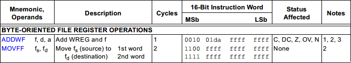
The "MOVFF" instruction is a new one compared to the 16 series. With the 16 series in order to place the data from one file register to another you needed to place it into the working register first, it required two instructions. Using this command will use the same amount of memory and take the same time to execute however the status register remains unaffected unlike using two commands, this could be important in your application.
![]()
If you take note in the binary section you will notice the data is 12-bit, this is because all of our addresses in the RAM are 12-bit, this instruction says move data from address "a" to address "b".
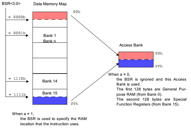
One more thing I should mention is the data bank that contains our file registers. In the first bank is an area called the "access bank" which can be accessed at any time without the need to modify the bank select register (BSR). Since all of the special functions registers are placed in bank 15 it means that the BSR can be used to select bank 15 and then the access register used for the common variables at any time.
Flashing LED Program
In the previous chapter I provided a program to make an LED flash to prove the setup was correct, the purpose of this section is to explain how that program works and the registers involved. Again here is a copy of the program - Program Text.
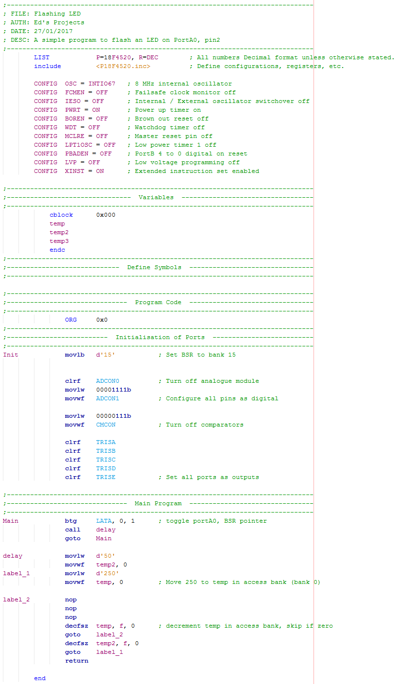
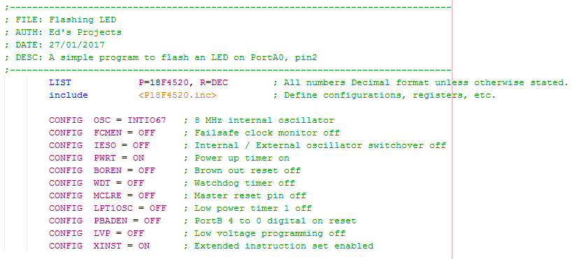
Configuration
The first part of the program is always the information header, it is not required but can be useful to specify the name, author, date, purpose and how the program may work. I have already explained what each of the parts in the configuration do in the previous chapter, it is always a good idea to annotate the program too, especially the configuration settings. I have chosen the internal oscillator and to enable the oscillator pins to be used as IO's. The power up timer is always recommended to allow the supply to stabilise and the extended instruction set enabled even if I don't use them.
Variables
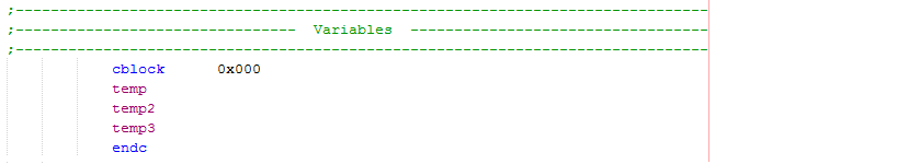
The variables are stored in our RAM, it is not necessary to label them like I have done in the example below but it's easier to deal with than just a hex address. The cblock allows us to label a particular file register, by starting at 0x000 the variable temp will be location 0x000, temp2 will be 0x001 and temp3 will be 0x002. The first 128 bytes is our access register which can be accessed any time in the program without having to modify our bank pointing register (BSR).
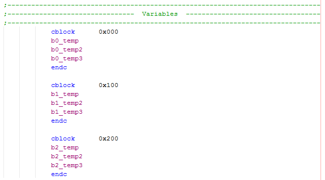
On thing to note is that for most of our commands the file registers are only assigned an 8-bit address meaning that temp is only addressed to 0x00, temp2 to 0x01 and temp3 to 0x02. If I was to be using our BSR then I could actually move data to temp in bank0, 1, 2 and so on. All of this means that our variable temp can be equal to 0x000, 0x100, 0x200, etc... and of course these are all different memory locations. Care must be taken if we choose to place our variables in other banks as the appropriate bank needs to be selected first, the only exception is the MOVFF command which deals with the full 12-bit address and therefore banks don't matter.
To help reduce confusion the variable should have some kind of indicator to say which bank it has been placed in such as that in the example below, by doing this the programmer will automatically know they need to select the correct bank before playing with that particular variable.
Define Symbols
This part can be beneficial to a program but it can also introduce some errors if care is not taken, as you can see I did not include any for the example program as they were not needed.

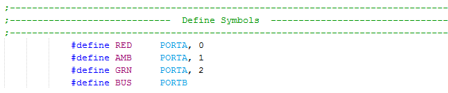
A symbol can be assigned to either a register bit or the whole register byte, what can introduce errors is failing to remember to switch to bank 15. If the registers are addressed by their original names then it's easier to remember to switch banks. I do admit they can be very helpful when dealing the PORT registers, for example I could assign three bits in portA to three different colour LED's, the symbols could be their colours which means more than just a port bit number.
Program Origin
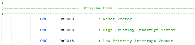
The origin of the program can start anywhere, for this program I chose zero.

As you will find in the later chapters there is a condition known as an interrupt that will cause the program to jump to either one of two different locations. On power up of the chip it will start at the reset condition vector known as ORG 0x0000 and run from there on. If an interrupt condition occurs it will jump to either 0x0008 or 0x0018 depending on it's priority. If a program contains a set of interrupt programs then normally there will be a command to make it jump to a separate section, likewise there will be a jump at the reset vector to jump past all of the interrupt vectors, this will all make sense later on.
Port Initialisation
This is the section that sets up all of the register configurations, it is normally only visited once at the start of the program.
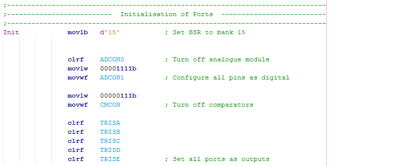
The first piece of program should have a label, this can be anything you write so long it starts with a text character and is the at most left column. I have chosen "Init" as this will be the intialisation stage of the program, this is the location we would jump to after the reset vector 0x0000. Since there is no program between the start and here we are actually starting at 0x0000. "movlb" is a command to move a literal to the BSR, by sending decimal 15 we are selecting bank 15 where all of the special function registers are.
![]()
The next section is to configure all of the ports to be digital and disable the analogue module. The "movlw" command is to move a literal value into the working register, since registers are binary it concludes that I load a binary value into it, I could of course use hex or decimal as it all equates to the same value. The "crlf" command is to clear the register, it's one instruction faster than loading zero from the working register via the "movlw" command.
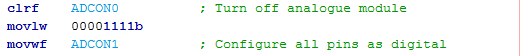
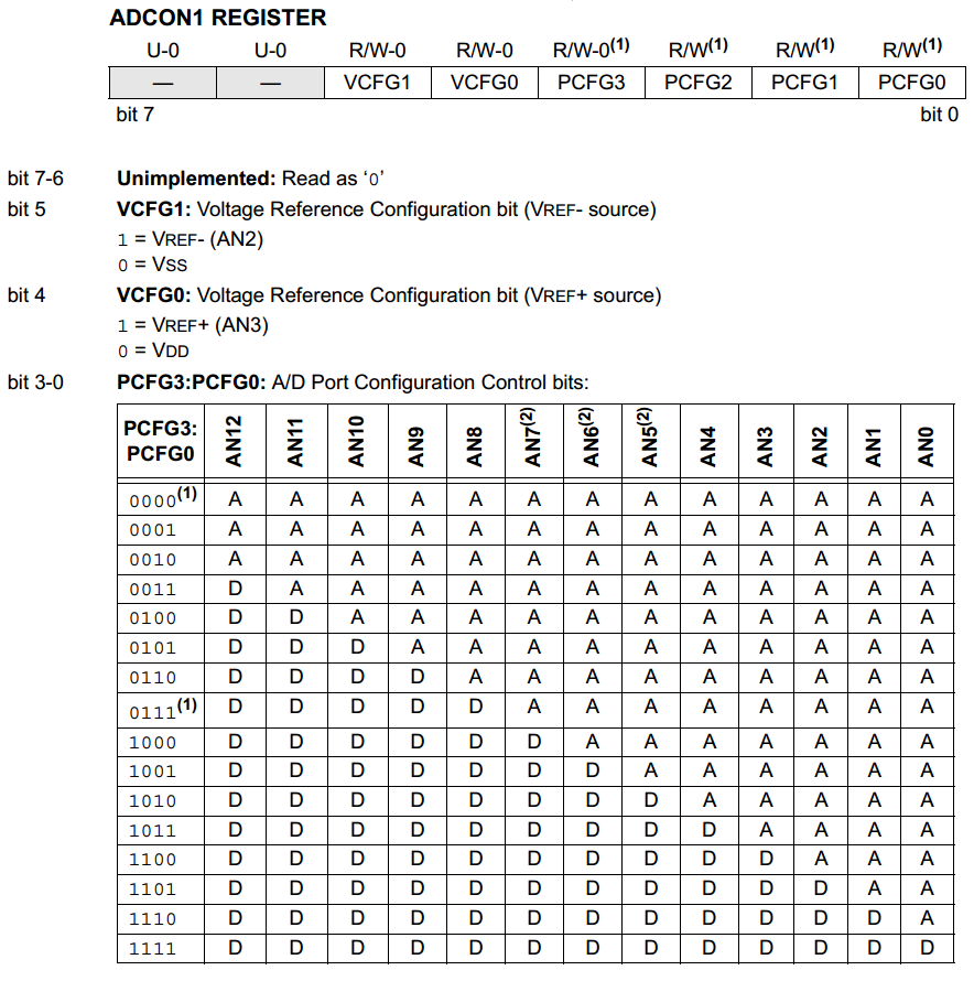
It is not necessary to do anything with the ADCON0 register as this is to control the analogue module and not the pins, since I will be setting all pins as digital I need to configure the ADCON1 register. All registers will have a page to themselves like in the following extract, this will tell us what each bits function is, a bit in a register is also known as a flag. Following the sheet it concludes that I set the register to 00001111 in order to set all pins as digital.
Another feature of the microcontroller is a set of comparators, these are often not used and therefore must be disabled. I'm not going to go into detail of the register but the bits 0 to 2 control how the comparators are connected to the pins, this configuration disconnects them.
![]()
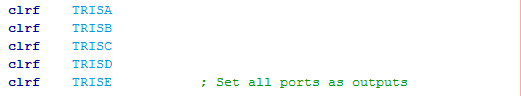
Finally there is the section which configures what our input / output pins are doing. The TRIS register is to control whether a pin is an input or an output, a 1 will represent input and a zero output. It concludes that by clearing all of these registers, setting them as zero, will set all pins to be outputs. There will be some exceptions where some pins can only be inputs but this doesn't matter until I need to use that pin as an input.
Main Program
After the initialisation our main program is ready to start, it is always wise to place a label at the beginning as you'll likely loop back to it.
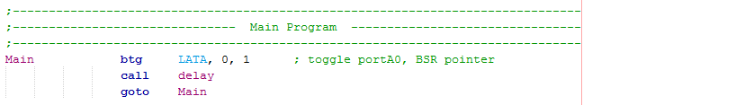
The first line contains an instruction known as a "bit orientated command" which like it says will only affect one bit. "btg" is known as bit toggle, so whatever bit is there previous will be the opposite afterwards, this is a very useful command. The command is laid out in the format of "btg f, d, a". The LATA register is what controls the outputs on PortA, we are therefore proposing to toggle bit0 with the register from the bank, since it was set at 15 earlier it concludes we want to toggle an SFR, exactly where the LATA register is located. There is of course two ways of writing this line, the second method is the better method as shown below. The output of this port is connected to the LED, toggling the bit continuously will make the LED flash.

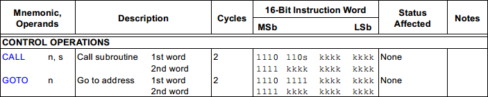
Once the bit has been toggled we next to call up a subroutine for a delay program, once returned it will jump back to the beginning to loop again (jump back to Main label). The "call" and "goto" commands are known as control operations, these two modify the program counter causing a jump to a different location in program memory.
![]()
It's best to take a closer look at both of these commands as they are double word commands. Both of these commands will modify the program counter to jump to a different location, the difference is the call command will save the current program counter location in the stack. If you take a closer look at the bits used you will notice the k's which is the location we want to jump to, of course the compiler does work this out for us and the reason for 2 words is because there wouldn't be enough room for the address in just one.
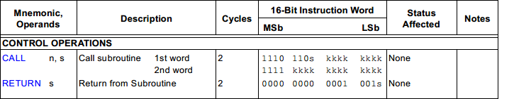
After a subroutine has been executed it must be returned via a "return" command as you will see later on. You may have noticed the "s" in the call command and you may also notice the one in the return command too. There is a "slow call" and a "fast call" likewise there is a "slow return" and a "fast return". They are normally done in pairs but quite simply whatever is in the working register, status register and the BSR may be modified in the subroutine. Using the "fast call" will save these values and using the "fast return" will return them, so basically it doesn't matter what happens in the subroutine you can return with what you began with.
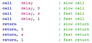
Here are the different ways in which a call and return can be written.
The last part to discuss is the delay program itself which is our subroutine. A subroutine is a useful way to repeat a particular part of a program, imagine writing this delay out multiple times. The first half of the program is pretty easy to understand as I'm simply loading two of my file registers with the values of decimal 50 and 250. Since the variables are located in the access register I place either a "0" or "a" after the variable.
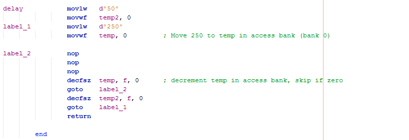
The second part of the delay is to cause a loop, since each instruction will take a certain amount of time it concludes that looping multiple times will create a delay. Our "nop" commands are one way of wasting an instruction cycle to add a delay. The next instruction "decfsz" has the meaning "decrement file register by one, skip next instruction when equal to zero". The temp register will decrement by one, reach the goto and loop again, once it reaches zero it will skip over the goto to decrement a second register, hit the goto to reload the first register and decrement that one again, this whole process is known as a "nested delay". Once the last register reaches zero it skips the goto and hits the return instead, our delay routine is complete.
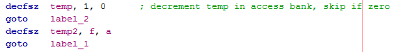
Don't forget that there are two different ways of writing the operands, it is always best to go with the text option as it's clear to read and therefore a mistake is less likely.
I hope this chapter has helped to explain how this program works and what some of the most simple instructions do. The next chapter will visit the flashing LED again but this time I will show how to configure the oscillator speed and how to calculate our delay.
Hello, if you have enjoyed reading this project, have taken an interest in another or want me to progress one further then please consider donating or even sponsoring a small amount every month, for more information on why you may like to help me out then follow the sponsor link to the left. Otherwise you can donate any amount with the link below, thank you!