18 Series - Chapter 4 - Oscillator and Delay
The previous chapter explained how the flashing LED program worked however it did not discuss how to calculate the delay. A big part of programming is the correct timing and the reason we use a resonant crystal instead of an RC circuit. There is no simple delay command with any microcontroller, apart from "nop" which is the no operation command taking an instruction cycle or 1/4 of the oscillator frequency. To create a delay one must loop a section of program many times, each instruction equates to a delay, the more instructions the longer the delay.
Before I concern delays I must first discuss the oscillator circuit and partly how the microcontroller works and why is one instruction 1/4 of the oscillator frequency. I will also discuss the oscillator options either internal, external or through microcontroller configuration.
The Data Latch
In almost all digital circuits there will be a clock source from the simple watch circuit to the most powerful computer that enables the data to flow. All microcontrollers will have a great number of shift registers and data latches, the purpose of these small circuits is to accurately deal with data.
Inside of the pin ports will be a set of data latches which control the data out and the data in. Here is a diagram of a port, this is for one pin only which means that there will be this set of hardware for every single pin. The purpose of the latch is that when data is inputted on the "D" pin nothing will happen until there is a clock signal on the "CK" pin which transfers the data from "D" to "Q", the falling edge of the signal triggers the latch. The data can change at any time on "D" but "Q" will not change unless there is a falling edge clock signal.
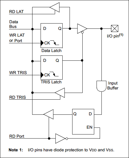
The reason for having a latch is to ensure that all data will be transferred simultaneously at a time we specify, in other words our instruction.
The middle TRIS latch is to control whether we want this pin to be an input or an output, this is of course why we set the TRIS registers.
If an output then it will switch on the gate between the Data latch and the output pin, it is our LAT register that control our outputs.
If an input then it will go straight to our PORT register in which it can then be read.
The data whether it's input, output or to set the TRIS register will only move through a latch on a clock cycle.
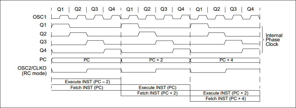
The next step is to explain the instruction cycling and why our instruction is 1/4 of the clock frequency. In the diagram below it shows our oscillator clock cycles, "OSC1" is the oscillator itself and the "Q's" are our clock cycles. In the first cycle of Q1 our first 8-bits of the instruction cycle are pulled from the program memory, Q2 places it in the processor. Since an instruction is 16-bit it follows that Q3 and Q4 is the other half of the instruction. Just to get the instruction from the program memory into the processor has taken four clock cycles or one instruction cycle. The next Q1 and Q2 decode what the instruction is and then finally Q3 and Q4 deals with the data, for example Q3 will place data in the output latch and then Q4 will output the data. The Microchip series of microcontroller use something called a "pipeline", it is pretty self explanatory as all of the data flows as through a pipe, this means that even though it takes two instruction cycles to output an instruction it really only takes one as when the first instruction has been taken from the program memory and sent on to be decoded the next instruction is read right behind as though traveling through a pipe, therefore an instruction is completed every instruction cycle, and hence 4 clock cycles ( Q1 to 4 ).
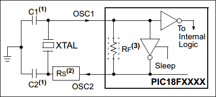
The next part is the clock source as this is what clocks our data along. Most microcontrollers will need an external oscillator for an accurate frequency, however most microcontrollers have some kind of an internal oscillator, RC, crystal or even both. The crystal is a piezoelectric piece of material that resonates when a voltage is supplied to it, the capacitors are to help keep the voltages to within reasonable levels for the microcontroller to process. A series of gates will shift the output clock signal when the crystal voltage changes direction, basically a flip-flop.
Below is a voltage trace taken from the oscillator of a microcontroller, the crystal is 20MHZ, as you can see the voltage is a sine wave. Another thing to notice is that the voltage is not perfectly sinusoidal, there is sometimes a second harmonic as shown by the third bottom peak. This little "hiccup" is only around 100mv (10x probe) and shouldn't be detected by the microcontroller, sometimes choosing the "right" capacitors may resolve the issue. If the "hiccup" is too great it may trigger an additional clock cycle.

Here is an internal block of the oscillator system, essentially there are a total of three possible clock sources with frequencies up to 40MHz external and 32MHz internal. Since the internal speed is already high I will choose this method to increase the number of IO's.
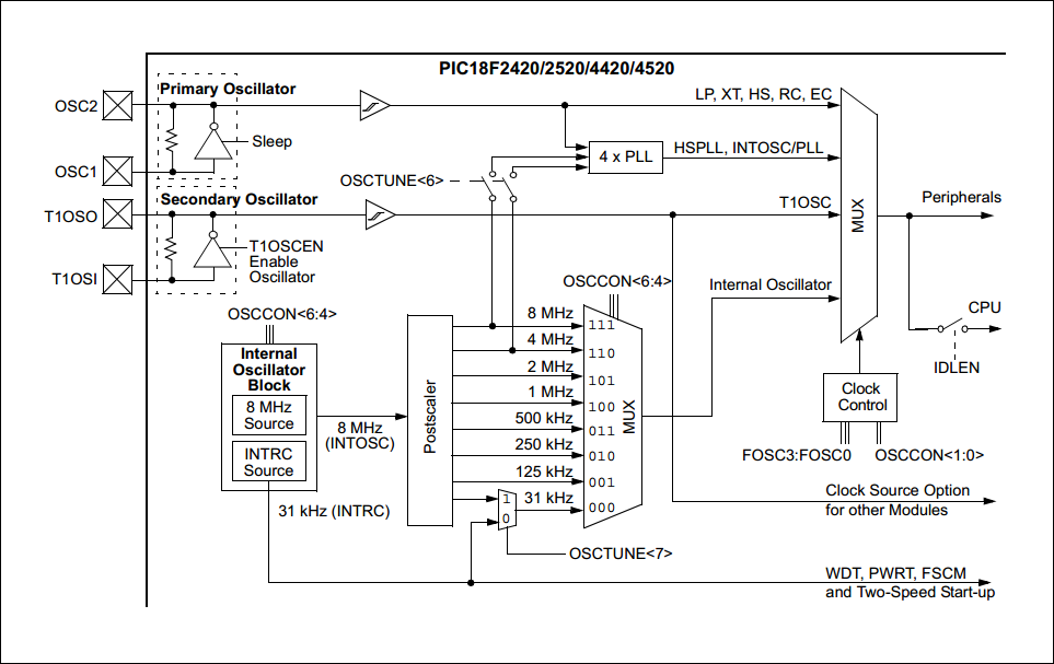
In the configurations at the start of the program I can select the basic oscillator source as being internal, this will default at 8MHz for this particular type of microcontroller. In order to increase the frequency there are two registers I must deal with "OSCTUNE" and "OSCCON", this is quite clear from the above diagram.
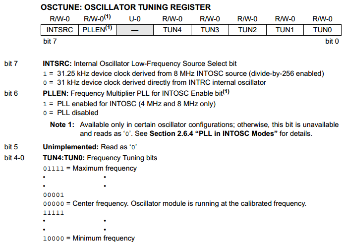
The first register is the oscillator tuning register which serves two purposes, it allows us to select a frequency multiplier and allows us to tune the internal 31kHz RC oscillator.
The RC oscillator is normally used for low power applications or those that don't require a high operating speed such as a clock. An RC oscillator is often inaccurate and can fluctuate due to temperature, the tuning bits are there to help.
The part I'm interested in is the PLL which multiplies our oscillator frequency by a factor of four. Since none of the other bits matter I can simply write "01000000" into this register.

This is the most important register as this controls our oscillator source and the post-scaler.
The post-scaler is used in conjunction with the internal 8MHz oscillator and allows us to divide it down into smaller frequencies.
The most important part are the bits that control our oscillator source either being internal, primary external or secondary external.
From the datasheet I will be selecting the internal oscillator and run at it's maximum of 8MHz, I would set this register to "01110010". There is a little confusion in the datasheet as when using the internal oscillator with the PLL one must select the "primary oscillator" option instead. We would actually set the register to "01110000".
Programming
The changes to the program are rather simple, since the oscillator will likely not change it is wise to set the configuration in the initialisation stage near the start of the program.
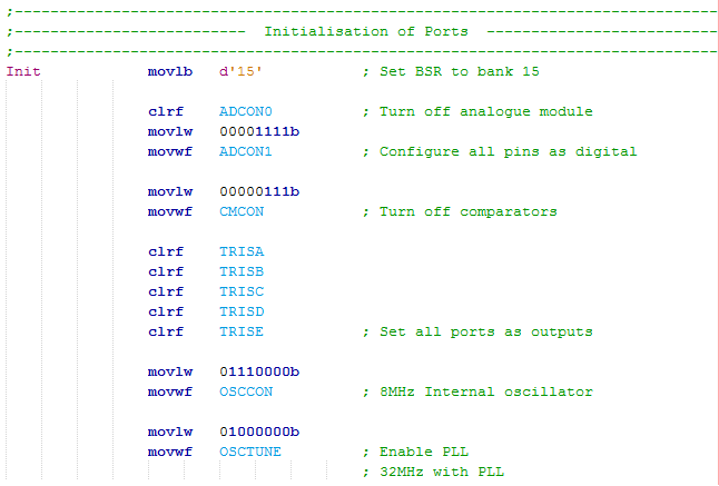
It simply requires us to load the working register with our binary values and then place it straight into the SFR register. If there is no directive pointing to which RAM bank we place the value in then it will automatically default to the BSR.
One thing to note is that the OSCCON must be dealt with before OSCTUNE as you can't activate the PLL until the oscillator source has been specified.
Delays
To make the program a little easier to follow I have added a few additional "nop" commands, this will become clear.
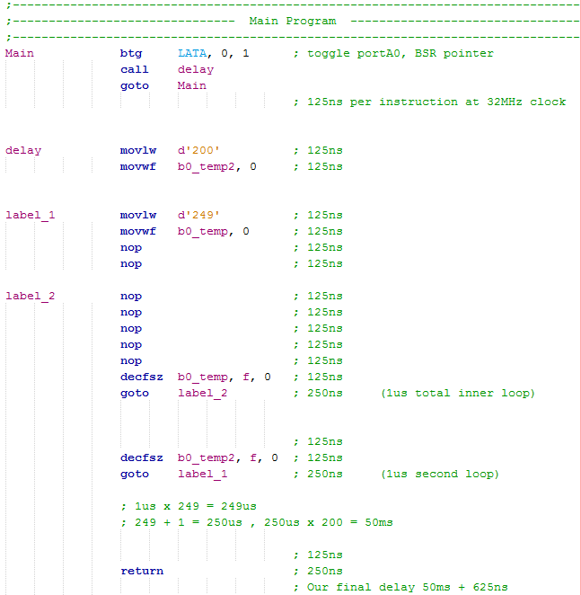
The first part of the delay loads a temporary register, since the instruction runs at 8 MIPS it concludes each instruction takes 125ns. The first two instructions taking a total of 250ns.
A second temporary register is loaded, a further two "nop" commands added which will make our calculated delay easier to work out.
The inner core of the delay has an additional few "nop"s added in order to make the delay easier to work with. The "goto" command will take a total of two instruction cycles as explained in the previous chapter.
The "decfsz" command takes one instruction cycle if not zero and takes two instruction cycles if zero, hence the extra 125ns added.
And then finally a return command taking an additional two instruction cycles.
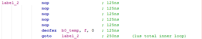
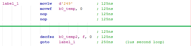
The first part to dissect is the heart of the cycle, the inner loop or nest. I have added an additional two "nop" commands in order to bring the total time to 1us as this is an easy number to work with. It is always worth labeling delays like this to ensure the correct time is taken.
The second delay is to loop the above section a number of times, it does this by decrementing the second variable and looping back to run the first loop again. After the zero branch there is a 125ns delay due to the "decfsz" command and then a further 375ns for the second decrement and the "goto" command. The "goto" command loops us back to reload the first variable and run through the two "nop" commands, these take an additional 1us to complete.
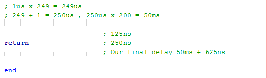
The first delay will run a total of 249 times taking a total of 249us to complete, when it branches it hits the second delay cycle taking a further 1us to complete, a total of 250us. The second delay will loop all of this a total of 200 times multiplying our delay to 50ms. The first two instructions and the last instruction adds an additional 625ns to the process, since this is such a small amount for a large delay it can normally be forgotten, however I could alter the delay routine to remove it if necessary.
To check the delay I connected an oscilloscope to the output, it should equal around a 10Hz signal. It looks pretty much perfect to me, the scope saying the frequency is 9.98Hz which could be due to an inaccurate oscillator or simply the resolution of the oscilloscope.

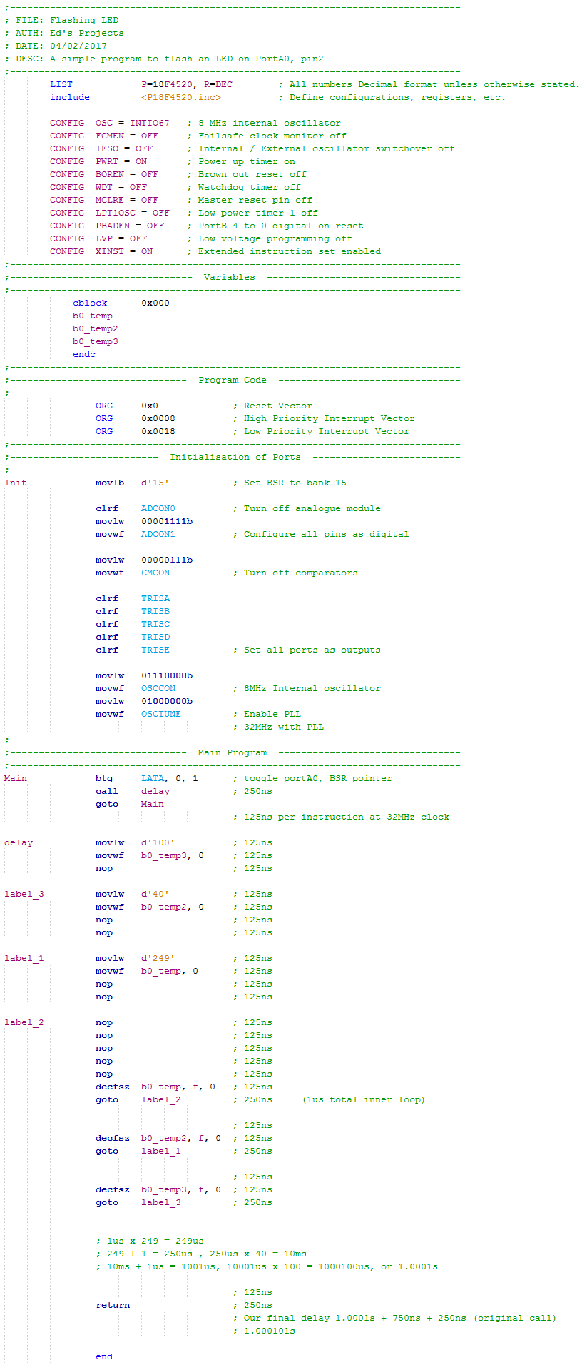
Most delays are not this short so you may have to nest three times like the example I give below. I have tried to get the delay as close to 1 second as possible but there is however a 101us additional delay. I could reduce some of the loops and then add a third separate loop to make the delay up to exactly 1 second but it's likely my oscillator isn't that accurate anyway. Here is a copy of the program - Program Text.
This has been a short chapter on delays, remember that the internal clock will have a certain accuracy, typically 1% and that by increasing the frequency by a factor of four will also increase the tolerance by a factor of four. For precise timing applications it may be wise to use an external oscillator. The next chapter will deal with some inputs, it will be a fairly short chapter.
Hello, if you have enjoyed reading this project, have taken an interest in another or want me to progress one further then please consider donating or even sponsoring a small amount every month, for more information on why you may like to help me out then follow the sponsor link to the left. Otherwise you can donate any amount with the link below, thank you!