18 Series - Chapter 5 - Inputs, Status and Mathematics
In this chapter I will discuss two important parts of the microcontroller, the inputs and the status register. The part on inputs will be relatively short since it's a fairly easy topic, the status register is mostly used for arithmetic as explained later.
Inputs
The basic input is digital, for now this is our only concern as analogue will be discussed at a later date. At the start of the program we specify what pins are inputs / outputs via the TRIS register. I want to make Port A bit 1 an input (pin 3) which means that I must set the bit 1 of TRISA register and leave all the rest zero. Below is an example of the changes made to the program and here is a copy of the program - Program Text.
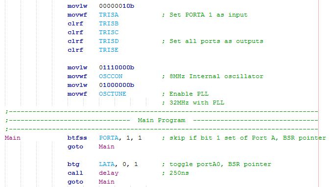
The switch is a bit test command, "btfss" (bit test skip if set). If the pin is positive it will skip and then toggle the output followed by the delay, if it is zero then it will continue looping back to main.
Imagine that we have a full set of switches on Port B which have to all be thrown in certain positions before the program can proceed. There are two ways of doing this but for now I will discuss a new instruction which skips if our SFR is equal to the working register. Here is a copy of the program - Program Text.
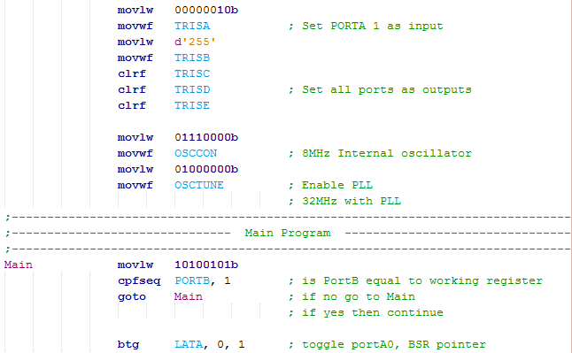
Since I want to set all of the pins of Port B to inputs I can either load hFF, d255 or 11111111b to the TRISB register.
I first load the working register with the value that I want to compare, the command compares to the FSR (PORTB) in regards to the BSR pointer (the 1 at the end, 0 if access register). If equal it will skip the next instruction, if not then it will read the next instruction, "goto main".
I think the two examples I gave above are enough of an explanation of how to deal with digital inputs.
Status Register
A register that may be used quite often is the status register. In the 16 series of microcontroller the status register was used very frequently to switch between banks, since this is not needed in the 18 series it is used far less. Another reason for the status register is to check the result of a mathematical procedure such as is the result higher than 8-bit, is it zero or is the result a minus. A lot of the instructions in the 18 series negate the use for status register for most occasions.
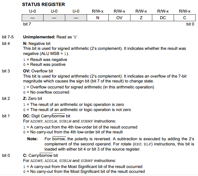
After some arithmetic we will get a result in the working register, in many occasions it may overflow, become negative or be zero. The status register is used to tell us what the result is.
The negative bit is used for "signed arithmetic" which means that if bit-7 is a zero then we're positive, if it's a one then we're negative. This allows us 127 to -128 instead of 0 to 255.
The overflow bit is again for signed arithmetic, this tells us if we exceed our -1 value and go back into positive (11111111 overflows to 00000000).
The zero bit will flag simply if our result is zero.
The digit carry is for if we exceed the low nibble, so for example moving from 00001111 to 00010000 will set this flag.
The carry bit is for unsigned arithmetic and will flag if we exceed our 8-bit register, the borrow bit is for using a subtract command.
The status register may seem a little confusing at first but it will become clear as I show a few examples, for most of my projects I will be using unsigned arithmetic as signed is dealing with negative numbers and that's not very often.
Mathematics
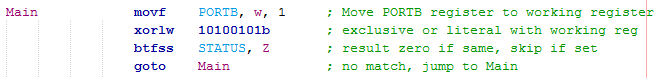
A lot of the processes will involve some kind of arithmetic, an example of this is to check that our input port matches a value we've set. This following example does the same as the "cpfseq" command, it's a longer way and is how it was done with the 16 series. Firstly PortB must be loaded into the working register from the FSR pointed by the BSR (move portB to w via BSR). Next is an instruction called "exclusive or literal" (XOR) by the instruction "xorlw" which if two bits match the result will be zero, if they all match then the result in the working register is zero. The status register is then checked to see if the zero bit has flagged, if so it means that all of our values have matched.
Addition
Another example may be that our input represents a value to be used elsewhere in the program, imagine a remote with the binary switches that have to be thrown in a certain way to equate to a certain frequency. Firstly we move the value of 100 to our working register, I then add PortB to the working register. The result in the working register is moved to a variable, the status register is checked to see if there was a carry, if so then a second variable would be incremented, if not then the increment command would be skipped.
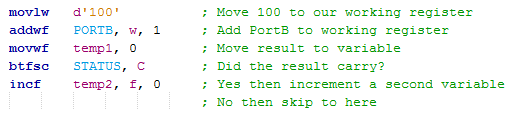
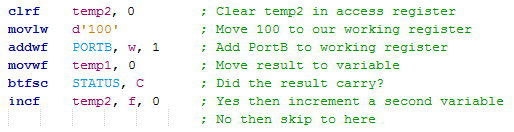
A little design consideration should be taken in the above example as if we were to run this program again and there was another carry then the result in temp2 would be even higher. It is best to clear a variable using the "clrf" command which clears a file register, I chose the access bank as all my variables are in there.
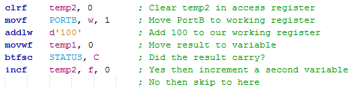
An alternative way is to move the port to the working register first and then add the literal value, it really doesn't matter which example you choose as they achieve exactly the same thing.
Subtraction
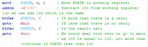
The subtract command is a little different as it will subtract the working register from either a literal or file register. Another option is to again use the "addlw" command but this time add a negative number, the compiler will work out the rest as we are secretly adding 156 to the register. So imagine 150 subtract 100 we get 50, or 150 add 156 we overflow and also get 50, our carry bit is set saying we don't need to borrow. Imagine 50 subtract 100 we get -50 which overflows to 206, or 50 add 156 we get 206, no carry occurred so our carry bit is not set and hence there is a borrow. You will notice a successful add will have no carry and a successful subtract will have a carry.
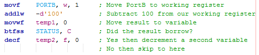
To subtract a number from a register you must first load the working register with the value you want to subtract, so for example I subtract 100 from PortB. Sometimes a problem is that we want to subtract a value from the working register, this can be done but it is much simpler to use a negative addition command such as "addlw" or "addwf".
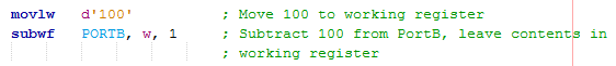
The following example will load the working register with our value form PortB, it will then be subtracted from 100.
![]()
Comparisons
Another huge chunk of microcontroller programming is the use of the equal to, above or below scenario. In the 18 series there are three main instructions for these situations however it is helpful to know that these are based on either the "xorlw", "addlw" or "addwf" commands. We have already discussed the "cpfseq" and "xorlw" commands for finding something equal to.
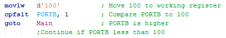
This first example is to deal with a less than, so firstly I can use the command "cpfslt" which means to compare "f" with the working register and skip if less than. This first example compares our PortB with 100 and skips if PortB is less than 100.
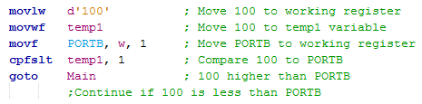
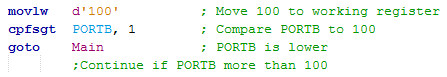
A little more code has to be introduced to do the opposite, this will skip if 100 is less than PortB.
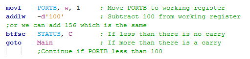
The alternative is to subtract the 100 from PortB which is the same as adding 156. So imagine that PortB is 99 then, 99 + 156 will be 255 and there will be no carry, 99 is less than 100 so we skip. Now imagine that PortB is 100 then, 100 + 156 will be 256 / 0 leading to a carry, in this case we could check the Z to see if we are equal to zero, so PortB equals 100. Finally imagine PortB is 101 then, 101 + 256 will be 257 / 1 leading to a carry, we are therefore more than 100 and therefore no skip.
To skip if PortB is more than 100 I could simply change the program to the following. I have added a little section in to see if we get an equal to result, since 100 is not more than 100 we could go back to main or the program could deal with this result in a different manor.
The piece of program that I would use is the following as we have a dedicated instruction to deal with the above.
Multiplication
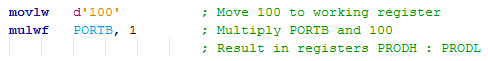
A great feature with the 18 series is the addition of a multiplication module. To use an algorithm would take around 70 instruction cycles to complete, this is the case for the 16 series however it can now be done in one instruction cycle. We simply multiply what is in the working register with a file register, the 16-bit result is placed in two registers "PRODH" and "PRODL". It really is that simple. If you're interested in how the algorithm works for the 70 instruction cycles then there is a mathematics section in my 16 series chapters.
Division
Division is always thought to be a difficult subject and can be quite complicated in microcontrollers, it requires an algorithm. I'm not going to thoroughly explain how the algorithm or the program works because at this stage it may be a little difficult to follow, this is good practice to research what each of these new instructions do. Here is a copy of the program - Program Text.
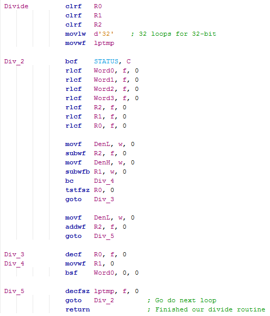
Firstly the program will require a total of three temporary variables and a fourth variable to let our program loop a total of 32 times. This division program is capable of 32 divide by 16 bit.
From Word3 down to Word0 (High to Low) is our input value, it will also be our output value at the end. DenH and DenL are our denominator variables, the number we want to divide by.
In basics the algorithm works on subtraction, for example 10 / 4 = 2.5, which is the same as 10 - (2.5 x 4). The algorithm works by subtracting the denominator from our temporary variables and then shifting all of the registers left, this repeats a total of 32 times.
It is quite hard to explain without a diagram but this is pretty much the standard procedure when dealing with division, it is unlikely you will find anything shorter than the example to the left.
The division process is rather slow, there are sometimes easier examples. One of these may be the division by 2, 4 or 8 as shown by the example below. To divide by a multiple of 2 you can simply shift the register to the right or to multiply by a multiple of 2 your can shift the register to the left. The commands to use are "rrcf" and "rlcf".
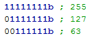
Another example may be to use multiplication and then a register shift. Lets for example say I want to divide 240 by 5, the answer would be 48. I could also multiply both sides by 51 to get 12240 divide by 255. If I place the 12240 in two registers I get 0010 1111 1101 0000, if I forget the lower register and go for 00101111 then the result would be 47. This may not be such an accurate method but it is a lot quicker than the division cycle and may be suitable for your application, that's if the denominator is a constant.
I hope I have done this chapter justice in explaining how we might deal with some inputs and the arithmetic involved. I think there has been enough talk up to now on the basics, the next chapter will introduce the character LCD as these are quite commonly used in projects.
Hello, if you have enjoyed reading this project, have taken an interest in another or want me to progress one further then please consider donating or even sponsoring a small amount every month, for more information on why you may like to help me out then follow the sponsor link to the left. Otherwise you can donate any amount with the link below, thank you!