18 Series - Chapter 6 - Character LCD
Quite commonly a character LCD is used in a project that only needs to display some basic alphanumerical data without requiring much memory to do so. A character LCD contains a certain number of segments depending on the chosen model, each segment can be told to display a particular preset character or a small number of user defined characters. The displays come in a wide variety of colours and sizes, for this chapter I will be using a 4 x 20 white backlit character display.
HD44780
Pretty much all of the character LCD's will be the HD44780 style of controller. The HD44780 was originally a chip by Hitachi that is a controller for the character display itself, now there are many replica's doing the same thing but even though they do not use the HD44780 chip they are regarded as this standard.
The HD44780 controller is a display multiplexing chip that can control up to 80 display segments, each segment is made up of 5x7 pixels. A character LCD will already come as a package with the chip integrated into it, what we get to interface with are a total of eleven control pins.
Firstly here is a diagram of a typical pinout for a display, it is for the one I'm using in this chapter.
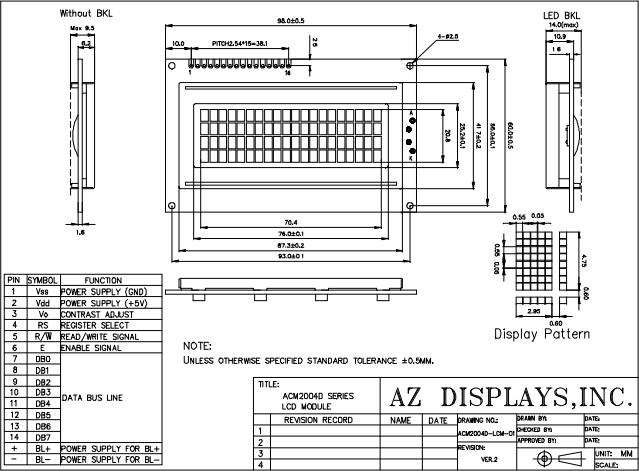
What is most important to us is our pin assignments.
The power supply pins are self explanatory, a maximum of 5V. The back light also requires 5V but needs a 7 ohm current limiting resistor, personally I use 22ohm and it's bright enough.
The contrast adjust determines how bright our pixels are, this should be biased via a potentiometer between +V and 0V. The voltage is around 0.63V to get a clear level of visibility.
The enable signal is our clock that allows data to move in and out.
The data bus is bi-directional, we can send data to the LCD or receive data from it.
Read / Write is to determine which direction our data bus is heading.
Register select is to switch between writing an instruction to the display or writing a character to it.
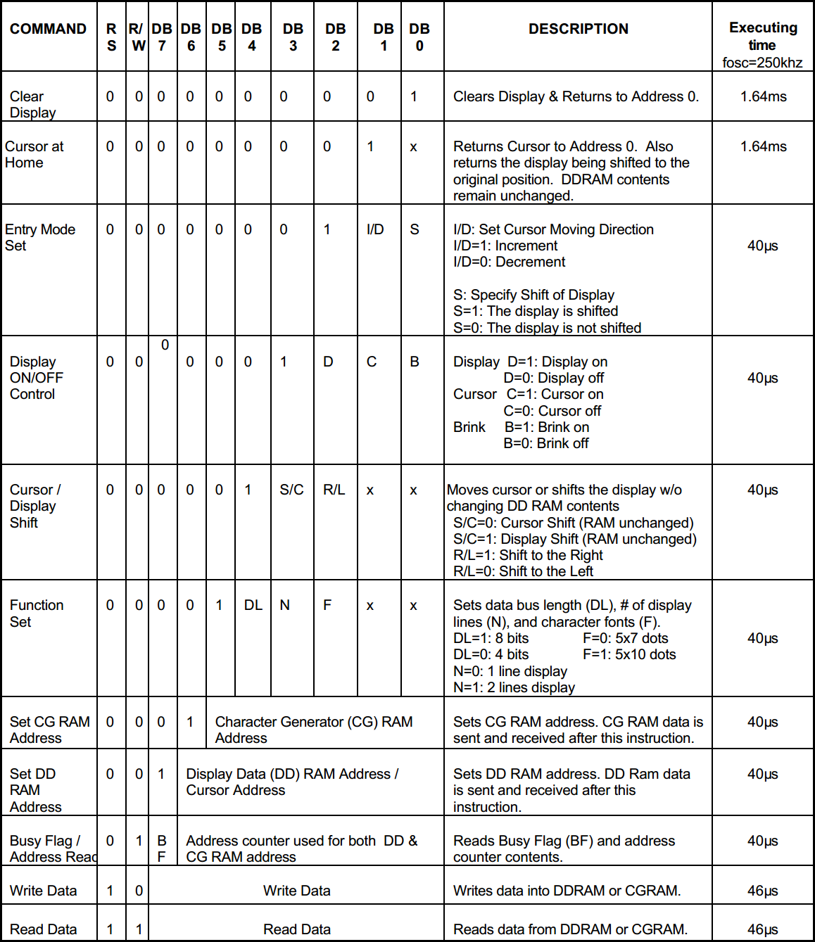
Towards the beginning of the datasheet will be a instruction list for the display, this is what we regard as our HD44780 set of instructions. Our set of instructions are used to turn on the LCD, set the cursor position, set how the display increments, the size of the display, the size of the characters and also the ability to write new characters. The important thing with the instruction list is it shows us what data should be sent to the pins, a clock of the enable pin will move the data.
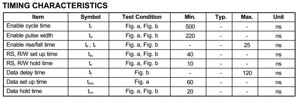
When data is to be written to the LCD it will take a certain amount of time to complete the action before the next byte of data can be sent. A delay can be used or the display can be read to see what it's status is, is it ready or busy. It is common practice with the character LCD to use a delay but the faster method would be to check the status, for some reason this LCD has issues with the read. Since I will be using the delay method you will need a timing diagram such as the one below.
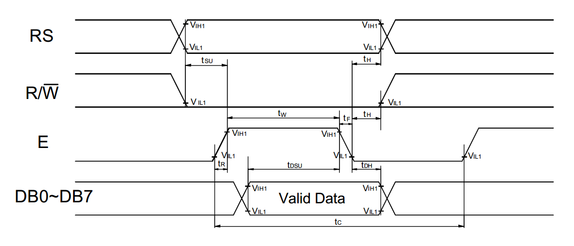
The reason we need such a diagram is because our microcontroller will run at a faster speed than the LCD. Since each instruction will take a total of 125ns to complete on the microcontroller it means that according to the diagram below I only need to use delays for the enable cycle. So simply I would raise the enable pin, pause two or three nop cycles, drop enable and pause another couple of nop cycles. It is always best to use longer delays that specified. Before the next lot of data is to be sent I would wait the instruction execution time, I may wait 10ms for the display clear and 100us for the rest of the instructions as an example.
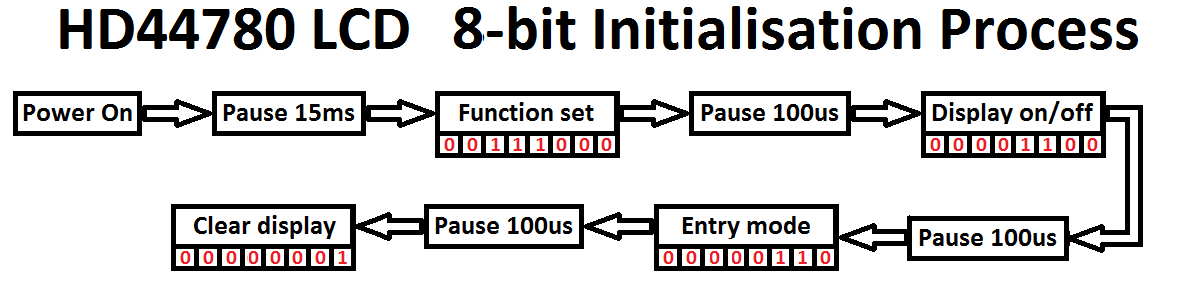
Initialisation
Like almost all hardware the character LCD needs some kind of an initialisation procedure, fortunately it is rather easy. There are two possibilities when sending data to the LCD, either 4-bit or 8-bit mode. The 4-bit mode uses just four data pins but still sends 8-bits of data, it is sent in two sections. If you want to use 4-bit mode then check out the chapter in the 16 series, 8-bit mode is fool proof and that's what I use in this chapter. All of the delays given in the diagram are exaggerated to ensure the data is processed properly, after the clear display a delay of around 1.6ms is specified in the instructions but I would at least double this.
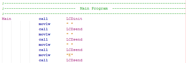
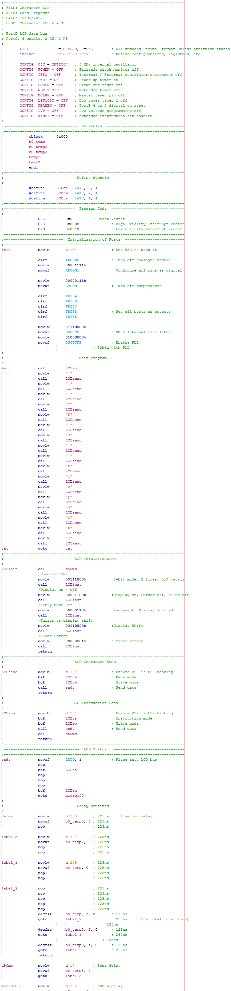
Here is an extract of program I use for the initialisation, it is initiated by a call.
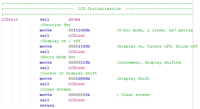
Firstly a delay of 50ms is implemented to allow the LCD's clock source to stabilise.
8-bit mode is set, 2 line mode and 5x7 matrix. Most LCD's will come as 5x7 matrix, 5x10 are very rare. The two lines all depend on how large the display is (40 characters per line).
Turn on display and turn off the cursor.
Increment and shift display to the right, both functions do this.
Finally clear the display.
It is wise to use two separate subroutines, one for data and the other for instructions. The instruction routine first loads the BSR with 15, where all of our FSR's are, this is just incase the program is expanded and the BSR is switched at some point. Both the RW and RS pins are cleared to set the LCD to write and instruction mode. A subroutine is called which sends the data and then a delay of 50ms before a return. Most of the instructions are done in 50us and the longest takes 2ms, a delay of 5ms would be more suitable, this program doesn't need to save time so 50ms is suitable, it saves me writing an additional delay cycle.
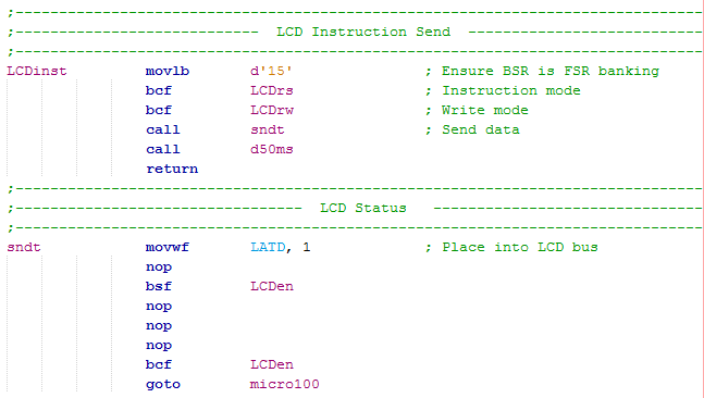
The send routine moves the data from the working register to the port connected to the data bus on the LCD. A pulse of the enable pin sends the data. This routine is used for both the data and the instructions. The "goto micro100" is a small 100us delay program, a goto is used as the subroutine has a "return" command at the end.
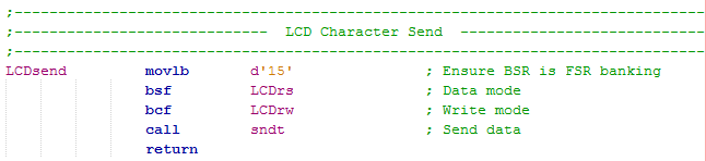
Data Send
The data to be sent uses the following program, RW is cleared to set write mode and RS is set to enter data mode. This time there is no 50ms delay as all data will only take around 40us to complete, in the send program is a little 100us delay.
A small section of the main program is as follows. By using the " " we can store a ASCII character in the working register (American Standard Code for Information Interchange). The ASCII character "A" for example can also be written as d'65', h'41' or 01000001b. All characters in computers will follow the ASCII standard, there is a table online if you require values of other characters, fortunately the compiler converts this for us by using the speech marks " ".
Full Program
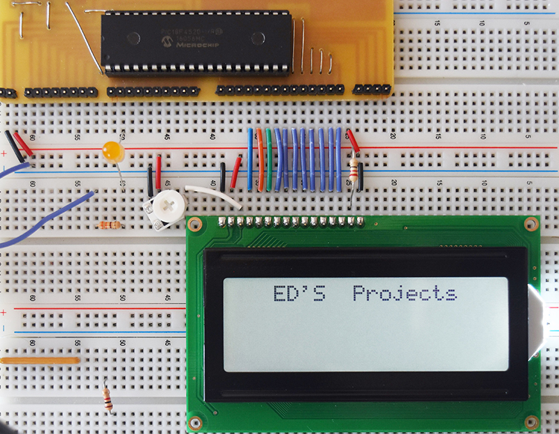
Here is my full program that initialises the LCD, clears it and then writes the message "ED's Projects". Here is a copy of the program - Program Text.
Here is the end result on the display.
Character Addressing
Clearing the display and writing each character again seems quite a wasteful way of writing data every time a small section needs to be changed. Imagine the LCD is for a temperature controller and the only part of the display that changes is the temperature itself, there is no reason to rewrite the rest. Each segment will have it's own particular address, we can point to this address and overwrite the contents. My LCD can display a total of 80 characters and is the largest a HD44780 controller can handle, it is known as a "2 line HD44780 display".
The two lines in the LCD are known as the DDRAM which is basically the cursor position as mentioned above, below is an example of these addresses in hex.
00 |
01 |
02 |
03 |
04 |
05 |
06 |
07 |
08 |
09 |
0A |
0B |
0C |
0D |
0E |
0F |
10 |
11 |
12 |
13 |
14 |
15 |
16 |
17 |
18 |
19 |
1A |
1B |
1C |
1D |
1E |
1F |
20 |
21 |
22 |
23 |
24 |
25 |
26 |
27 |
|---|---|---|---|---|---|---|---|---|---|---|---|---|---|---|---|---|---|---|---|---|---|---|---|---|---|---|---|---|---|---|---|---|---|---|---|---|---|---|---|
40 |
41 |
42 |
43 |
44 |
45 |
46 |
46 |
48 |
49 |
4A |
4B |
4C |
4D |
4E |
4F |
50 |
51 |
52 |
53 |
54 |
55 |
56 |
57 |
58 |
58 |
5A |
5B |
5C |
5D |
5E |
5F |
60 |
61 |
62 |
63 |
64 |
65 |
66 |
67 |
Or the table in decimal.
| 0 | 1 | 2 | 3 | 4 | 5 | 6 | 7 | 8 | 9 | 10 | 11 | 12 | 13 | 14 | 15 | 16 | 17 | 18 | 19 | 20 | 21 | 22 | 23 | 24 | 25 | 26 | 27 | 28 | 29 | 30 | 31 | 32 | 33 | 34 | 35 | 36 | 37 | 38 | 39 |
|---|---|---|---|---|---|---|---|---|---|---|---|---|---|---|---|---|---|---|---|---|---|---|---|---|---|---|---|---|---|---|---|---|---|---|---|---|---|---|---|
| 64 | 65 | 66 | 67 | 68 | 69 | 70 | 71 | 72 | 73 | 74 | 75 | 76 | 77 | 78 | 79 | 80 | 81 | 82 | 83 | 84 | 85 | 86 | 87 | 88 | 89 | 90 | 91 | 92 | 93 | 94 | 95 | 96 | 97 | 98 | 99 | 100 | 101 | 102 | 103 |
The LCD has to be placed into instruction mode and have value h80 or 128 decimal added to the above number to choose the cursor position. This is a useful way of reducing write time, it is a big help with data entry. You may find it particularly unusual that there is a gap in the address counter, what is more unusual is that line 1 in the address will equate to lines 1 and 3 on the display likewise line 2 in the address equates to lines 2 and 4 on the display. If you write a total of 80 character to the display the first 20 will appear on line 1, line 3, line 2 and then line 4.
If I wanted to write some characters to the display in the middle of line 2 then I would send the instruction 11000111b or 128 + 71 (199). Here is an example of code.
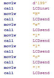
Here is the result.

Custom Characters
Another option in the LCD is to store up to eight custom characters which can been seen in the character set below, they are in the first column.
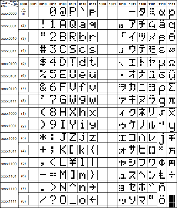
There are quite a number of characters that are standard to the display such as those to the left, these are known as CGROM and remain saved in the display when power is lost, this data can only be read.
As explained earlier if I wanted to write the character "A" to the LCD then I would write the following binary "01000001", decimal "65" or hex "41".
Another example is writing a number to the display such as zero, if zero in decimal was sent to the display then it would bring up some specialised character. Writing zero in ASCII which is normally written as "0" will in fact write the value "48" to the display, which in turn would present the character zero.
So what happens when you make some kind of a calculation in your program and you end up with a number such as 123. The number would have to be broken down into three digits, each digit would then be required to have the decimal number "48" added to convert it to ASCII.
What happens when you don't have the character that you require, you create one, up to eight can be stored in the display. The characters are stored in the first column known as CGRAM which will be lost when powered down.
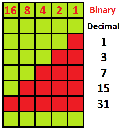
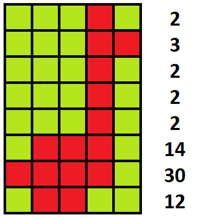
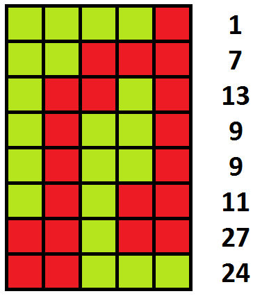
So how do you create a new character, firstly you need to know what your character needs to be. Even though the font in the function set is described as 5x7 the actual size of the segments are 5x8, the bottoms are missed off for the cursor. Firstly a matrix of the character needs to be created such as those below. As you can see you will end up with eight binary, decimal or hex values. I chose decimal as I find it easier to deal with.
Remember back to the function that sets the CGRAM address, this is used in conjunction with creating a character (CGRAM - character generation random access memory address). The size of the CGRAM is only 6-bit wide equating to 64 addresses, each address corresponds to a row of characters, 8 addresses make up one character and therefore there are eight characters total. When a character is created it is stored in the CGROM, where all of the other characters are stored.
| CGRAM address | CGROM address | ||
|---|---|---|---|
Decimal |
Hex
|
Decimal |
Hex
|
0 to 7 |
00 to 07
|
0 or 8 |
00 or 08
|
8 to 15 |
08 to 0F
|
1 or 9 |
01 or 09
|
16 to 23 |
10 to 17
|
2 or 10 |
02 or 0A
|
24 to 31 |
18 to 1F
|
3 or 11 |
03 or 0B
|
32 to 39 |
20 to 27
|
4 or 12 |
04 or 0C
|
40 to 47 |
28 to 2F
|
5 or 13 |
05 or 0D
|
48 to 55 |
30 to 37
|
6 or 14 |
06 or 0E
|
56 to 63 |
38 to 3F
|
7 or 15 |
07 or 0F
|
To create a character you must send the instruction d'64' plus our address as described above. For this example I have chosen the address to be zero, I send our 8 bytes of data and then end the process with a clear display instruction.
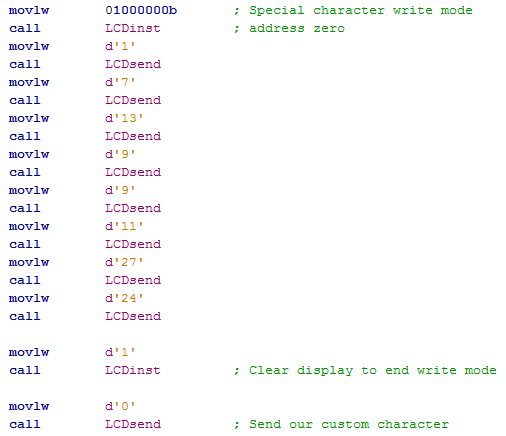
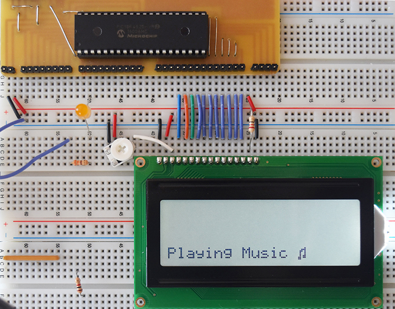
Here is the end result of the character along with some extra data to fit the genre of the symbol.
I think I have managed to cover all the important aspects of the character LCD, it is certainly worth getting used to how this display works because I will use it in a lot of the next chapters just because we can use it to view internal variable values. The next chapter will focus on another very important data input hardware, the numerical keypad. I will keep the next chapter a short one.
Hello, if you have enjoyed reading this project, have taken an interest in another or want me to progress one further then please consider donating or even sponsoring a small amount every month, for more information on why you may like to help me out then follow the sponsor link to the left. Otherwise you can donate any amount with the link below, thank you!