18 Series - Chapter 7 - Keypad
The keypad is a great tool for inputting alphanumerical data into a project. The keypad I have chosen for this project is a 4 x 4 alphanumerical kind but I will only be using the numerical aspect of the keypad. Take note that a keypad must be the matrix type, a 4 x 4 will have 8 pins, a pin for each column and each row. If you have a keypad that has a pin for every key then you can skip most of this page as the program will not apply.
Keypad Hardware
There are a few different styles of keypads to choose from, the majority of them will be split into rows and columns. Below is an example of the keypad I will use for this project, it is a 4x4.
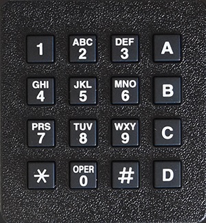

So how does this style of keypad work? Well for example we push the button one, it completes a circuit between row one and column one.
Imagine now that you connect all of column one to the positive rail, how do we know which key has been pressed, is it 1, 4, 7 or *?
To be able to determine which key is pressed we must only supply one column at a time, check all of the rows, power down the column, power the next column and so on.
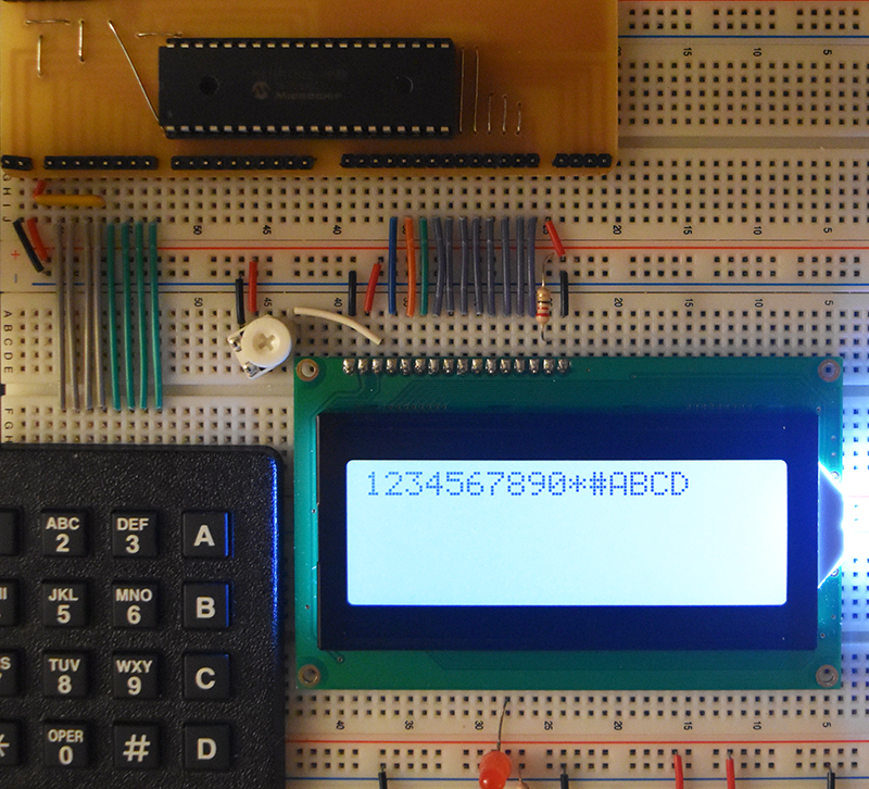
It is completely up to the user whether they decide to connect the columns as inputs or outputs and vice versa for the rows. I chose to connect the rows to inputs, you will need to use a pull-up resistor of around 4.7k on each input, the columns are then connected to outputs. I'm not going to spend time illustrating circuit diagrams as you should have at least a basic knowledge of circuit theory before reading these chapters. Below is my setup.
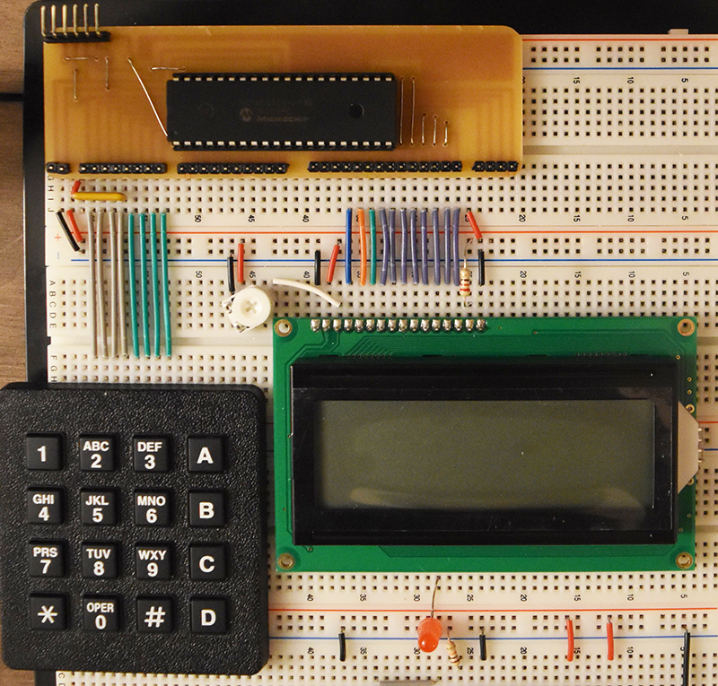
I prefer to use a 4.7k resistor network as a pull-up to keep the setup tidy.
Ignore the components below the LCD, they are from a previous project
Keypad Ports and Symbols
At the start of the program it is wise to define all of the pins as symbols as this will make the rest of the program easier to understand when reading.
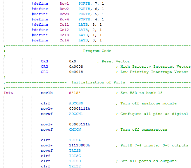
Remember that the inputs need to be defined as ports and the outputs need to be defined as latches, also remember that these are in the FSR in bank 15 and need to be pointed in that direction via the BSR.
The Tris register sets the direction of the pins, since the keypad is located on PortB it concludes that half are inputs and the other half are outputs.
Keypad Program
The first section of the program checks to see if a key has been pressed, the program continues to loop in this case but it could return if there are other external sources that need to be polled or other processes to cycle.
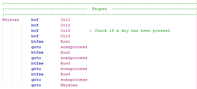
We clear all of the outputs, when a key is pressed it will pull the input pin down to zero, this indicates a button has been pressed.
If a key has been pressed then it will goto another section of program to decode which key that is.
The main section of program is pretty long but has simple function.
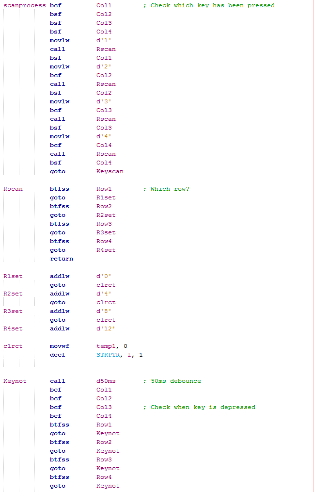
The scanning process will pull each of the outputs down before calling a subroutine to check if any rows have been pressed, a low will indicate a key has been pressed as they are pulled high.
After a column has been checked the pin is risen and then the next column is drawn low.
The working register is loaded with a value with regard to the column number, 1 to 4.
This section is called to after our column has been pulled low, if any of the inputs are low a key has been pressed and we jump to a section of program that deals with that row.
If no rows are detected then the program will return to try the next column.
When a row has been found the working register is then offset with another value, these values give us the numbers 1 to 16 representing the 16 keys.
Since we called a subprogram to scan the keypad and another to check the rows it concludes that we are in stack 2, we really don't want to return to the column check as we have found our key. The "STKPTR" stack pointer register needs to be decremented, by decrementing the stack pointer address we move the current program counter address to this location overwriting the "Rscan" call.
Afterwards a delay of 50ms is implemented to allow debounce on the key, all of the keys are checked to see if a key is still pressed, if so the program will continue to loop until the key has been depressed.
The Table Read
The table read command is used to help us read a section of program without having to jump anywhere in the main program. Previously in the 16 series of microcontroller I would have to modify the program counter to jump to a particular section of program to read some data and then return with that data, it wasn't difficult but did sometimes pose problems. Our table read uses an address pointer much like the PCL but doesn't require us to jump around, it also allows us to read only data whereas using the PCL could cause us to read an instruction instead.
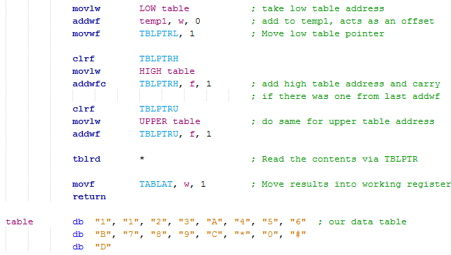
There are three register attached to the table pointer since our program addresses are 21-bit. Using the command "movlw LOW table" will move the lower 8-bits of the label "table" address to the working register, this is then added with our offset (the 1 to 16 from the keypad). The contents are moved to the lower table pointer.
Again the high address is moved to the working register, it is added along with a carry if there is one to the high table pointer.
The same is done for the upper table pointer.
There are a few different types of table read but the one with an "*" will read the contents and place them into the "TABLAT" register.
Our contents are read from the "TABLAT" register, the values represent ASCII, the value is returned and sent to the LCD.
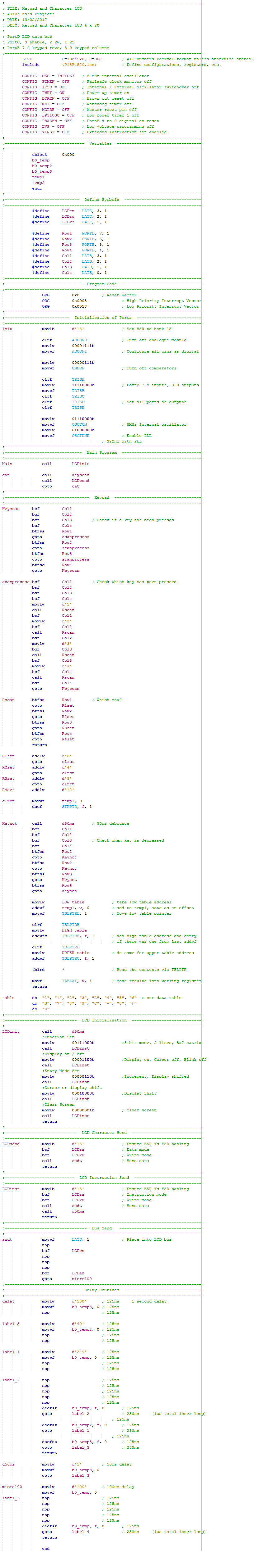
Full Program
Here is my full program that initialises the LCD, clears it and then scans the keypad for the user to input some data. Here is a copy of the program - Program Text.
Here is an example of the working program and the keypad characters on the LCD.
Once you have got the basic understanding of how a keypad is to be read it is easy to implement the program into other uses such as larger keypads, you could also implement it into a project with numerous buttons as this will reduce the number of pins required on the microcontroller (using a matrix button configuration). The next project will keep using the LCD and in the odd example use the keypad, the purpose of these chapters is to show you how to use the peripheral in question, sometimes the LCD and keypad can be a great aid with the process. The next chapter will concern EEPROM and FLASH memory.
Hello, if you have enjoyed reading this project, have taken an interest in another or want me to progress one further then please consider donating or even sponsoring a small amount every month, for more information on why you may like to help me out then follow the sponsor link to the left. Otherwise you can donate any amount with the link below, thank you!