18 Series - Chapter 9 - PCL and Stack
In a few of the previous chapters I have discussed both the PCL (program counter latch) and the stack. The purpose of this chapter is to show that we can modify the program counter to jump to different locations in the program, this was originally done in the 16 series to look up a value in a data table. The stack are the locations from which we jumped from to go do a subroutine, these locations can be edited so that the return is a different position in the program.
PCL
The PCL is the program counter latch which is our data memory pointer, or more simply it says which line we are at in the program. If I was to modify the PCL such as adding 10 to it I would jump forward 5 instructions, remember that each instruction is 16-bit / word long. There are a total of 5 registers associated with the program counter, these are;
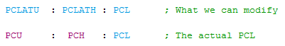
It may seem a little odd that we cannot directly modify the PCU or PCH but we can for the PCL. If you think about if we were to modify either the PCU, PCH, or PCL then a program jump would be immediate and only allow us to change one register. The reason for the PCLATU and PCLATH registers is that when these are written to nothing will happen until the PCL is modified, once the PCL is modified the contents of PCLATU will move to PCU and the contents of PCLATH will move the PCH. All of the program counter registers are modified at the same time giving us the program offset we requested.
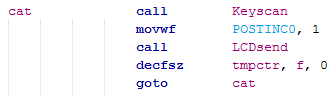
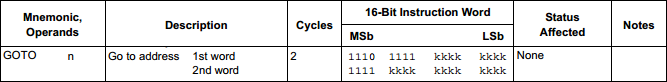
The first example I will show is the regular "goto" command and how it modifies the PCL. The following section of program will be used.
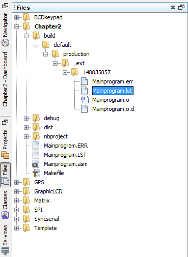
The first step is to find the list file that shows the program in Hex, follow the procedures here.
The list file shows us the locations that the HEX will be written to and the locations of the RAM. This shows use that the "cat" label is at 0x48 and that at the end of this little section we need to loop back to this location (0x48) via a "goto".
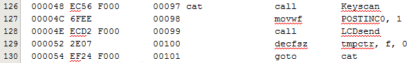
If you take a closer look at the instruction it's base will be 0xEF** F***. If you look at the last instruction in the above program you can see that the value is 0xEF24 F000 which means that we want a go to 0x24 which is half the "cat" label. For these commands the processor knows that it must double this value before it is placed in the program counter, this is actually just a case of shifting this value left one bit before placing it in the program counter, this is of no concern to us.
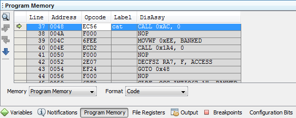
To see the program working I can run a simulation, so instead of selecting the PicKit 2 as the programmer I would select the simulator instead. To set the simulation running you must click "Debug Main Project" as shown below.

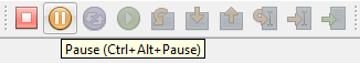
The program will begin the simulation for which you will need to select the "Pause" button.
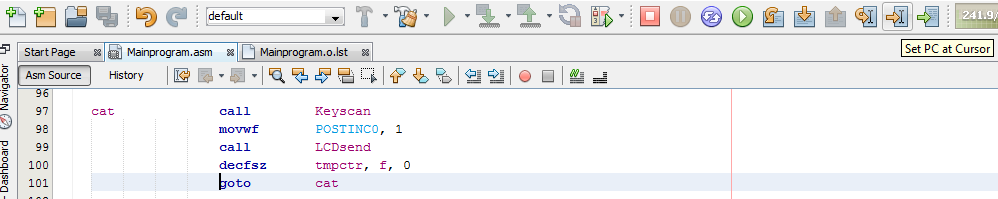
Then I set the cursor to the line I want to run and click "Set PC at Cursor".
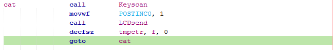
I will then get the following, the green line represents where the program is currently at.
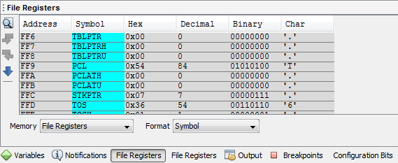
At the bottom of the page I can select the file registers and see what the contents of the PCL is, of course it should be at 0x54.
If I click "Step Into" then the program will increment one instruction which will set me to go to the label "cat".
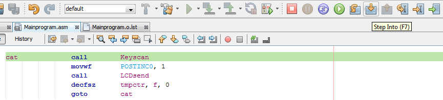
The contents of the PCL are now at 0x48.
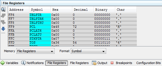
Using the debugging feature of the software is a very simple way to detect problems in a program and see if our SFR's contain the correct information. Another interesting feature is to select the program memory which will tell me all of the locations used, the operation codes and the assembly language used. You may also notice that some of the instructions will contain a "nop", this is because some are two instruction cycles long such as the "goto" or "call" commands, these are needed due to the long program counter addresses.
It's beneficial to know some of these features on the software and a must knowing how the microcontroller works. This second example is a computed goto to retrieve some information from a table, this was of course the only way of doing so for the 16 series, this can be done much more simply with the table pointer as we already know. For this example I will have a value named "offset" which I will use to jump to a specific point in a table in which I will return with some data.
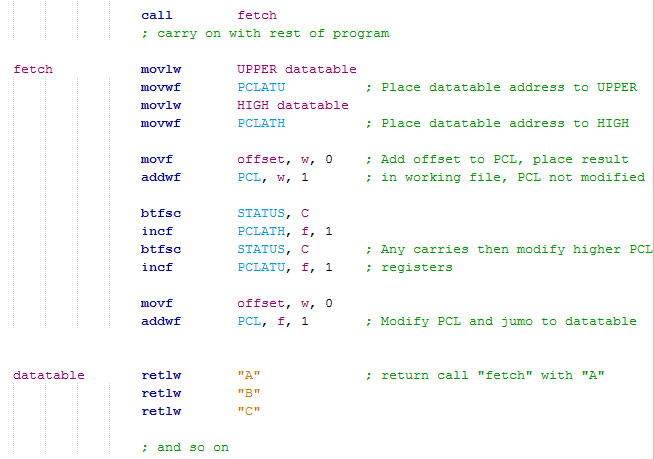
The program first begins by retrieving the address of "datatable" and placing it in PCLATH and PCLATU which will only move to the PCH and PCU when the PCL is modified.
We add our offset to the PCL but place the result in the working register, the PCL is not modified and nothing happens. The purpose is to see if our offset causes a carry to occur.
If a carry occurs then the PCLATH and PCLATU are incremented accordingly.
The offset is again added to the PCL but the value this time is placed in the PCL causing PCLATU to move to PCU and PCLATH to move to PCH.
The program counter has the address of the label "datatable" plus an offset which for this instance returns us with a value from the table, the offset determining which value. The "retlw" command returns from call with literal, we called the "fetch" program to begin with.
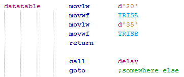
The example above shows us how we can retrieve a value from an address, the offset will determine which value this is. Since we are modifying the program counter we are jumping to a different place in the program much like a "goto" command except we have computed where, this means that the data table may not be data at all but another section of program. The following example could be change the configurations of some input pins or it could be used to jump to a specific delay, there really is no limit to the application.
Modifying the PCL is pretty clear as it's just like the cursor in the program, we can offset it to jump to specific places. There will be many more examples of the computed goto in future chapters and a lot of my projects.
The Stack
The stack is a total of 32, 24-bit registers that are to hold the program counter address. When a call is placed the current program counter address gets stored in the next stack, the first stack is the reset vector and cannot be written to, further nested subroutines will result in a higher stack. When a call is returned the current stack is read and placed in the program counter, the memory is then erased. There are registers and commands that allow us to modify the return addresses or even delete them altogether.
It's not actually that often that a stack will be modified, in fact I have only ever needed to do it once and that was for the keypad program. A scenario may be that we call up a program to check some data or ports, each one of these checks is another subroutine. If all is good then the program will return normally but we may hit the issue of that one of these subroutines triggers an event which requires me to return to the first initial call routine. The last call needs to be erased, the current stack value is the previous program counter call address, so basically we drop our current stack. The example below decrements the stack erasing the call, alternatively an instruction called "pop" will remove the current stack.
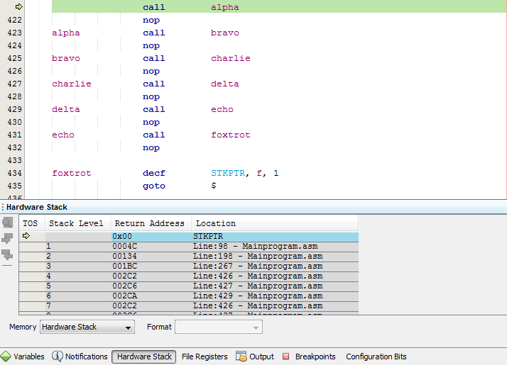
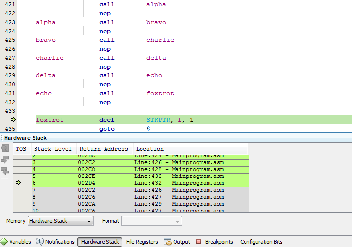
For this little section the stack will start at zero, like a program reset. Each time a call is issued the stack will jump up a place, so for example we are in stack 1 after jumping from line 421 in stack zero. Our current location is line 423, the current stack value is line 422 which is where the call will return, this is the line after the first call (we wouldn't want to return to line 421 and call again). I have added the "nop" commands in the program to make the return line clear.
After all of the calls the program is now in stack 6, each stack showing where the return line is.
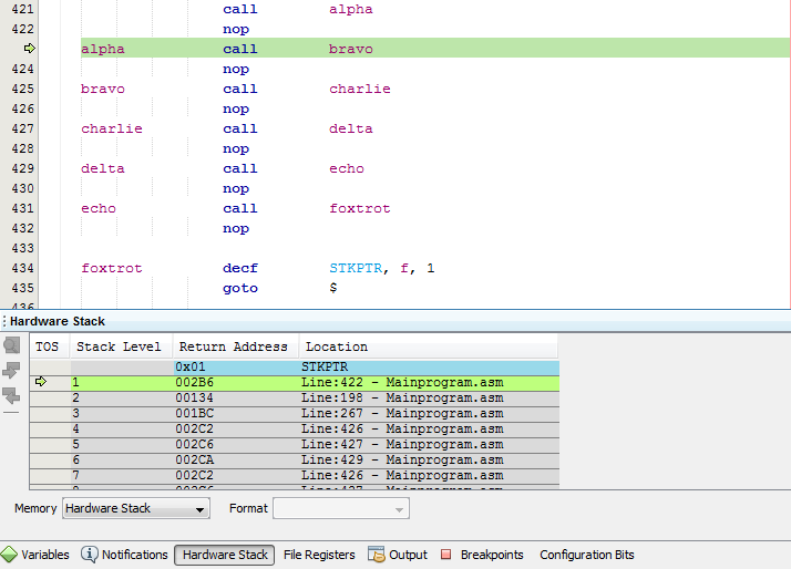
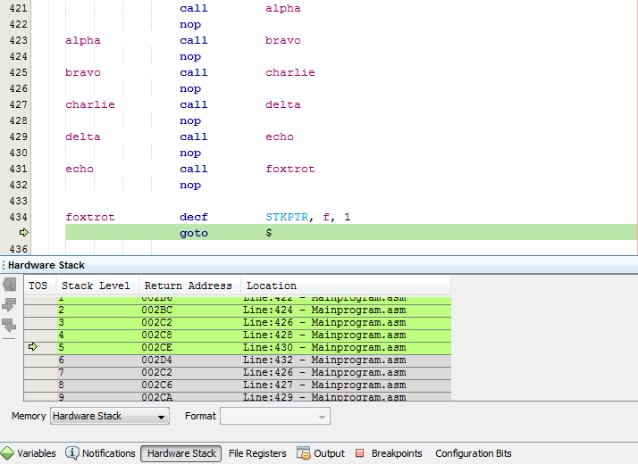
The stack register is decremented which basically erases the previous call command, so instead of returning to "echo" it would now return to "delta".
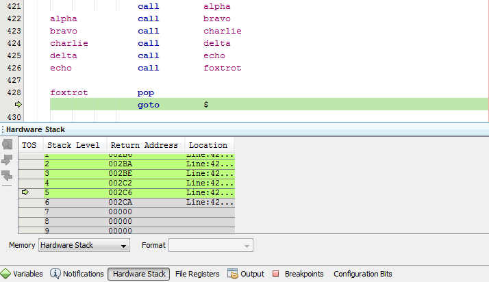
The alternative is the "pop" command which removes the current stack, basically a stack decrement.
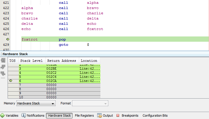
The stack after the "pop".
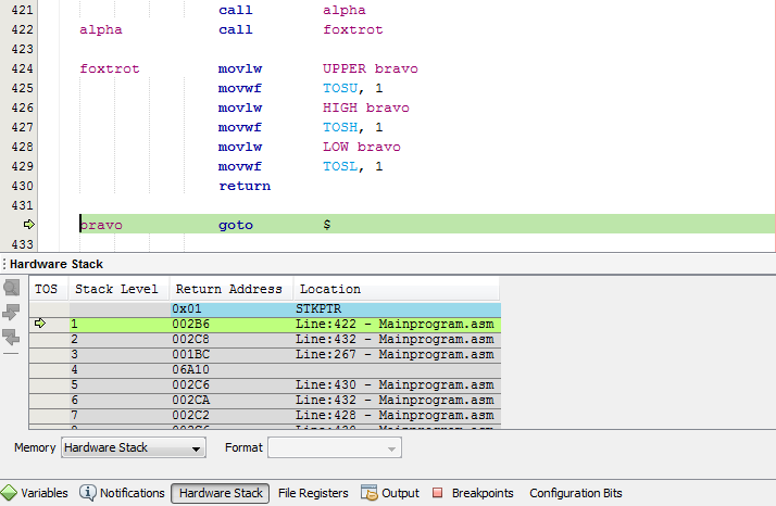
Now lets for example say I want to modify the return to a different area of the program. So according to the program below I will be at stack 2 at the label "foxtrot" in which I then load the address of label "bravo" into registers TOSU:TOSH:TOSL which is the return address, the return jumps me to "bravo".
There is nothing in stack zero because there is nothing to return to, so basically the current stack level is where we want to return. So say I'm at stack 1 and then call a subroutine taking me to stack 2, the previous program counter address will be placed in stack 2.
There are two commands that are attributed only to the stack register, these are "pop" and "push". There's not really much to say about these, the "pop" command remove the current stack and the "push" will add a stack with the current program counter location.
I think I have managed to cover most aspects of the PCL and the stack. I have also given some insight on how to view the program memory to see what things are doing and the simulation to increment through commands. The next chapter will introduce the ADC module that lets us read analogue.
Hello, if you have enjoyed reading this project, have taken an interest in another or want me to progress one further then please consider donating or even sponsoring a small amount every month, for more information on why you may like to help me out then follow the sponsor link to the left. Otherwise you can donate any amount with the link below, thank you!