Microcontrollers 10 - ADC - Analogue Digital Converter
Not all digital circuits deal with digital, most microcontrollers can infact convert an analogue input to digital data. This project is to use the last project like a data logger. The system will have three analogue inputs, when the correct code has been entered it will work as a datalogger saving the analogue inputs when prompted, such as temperatures. The values will be saved in the EEPROM, when the data has been acquired the datalogger can be locked again. The data cannot be viewed until the correct password has been entered. A project such as this could have the flash data and the EEPROM data locked in the configuration settings, this would make finding the data impossible without the password.
Firstly we need to know how to read analogue on the chip, these registers are something we normally disable at the start of a program. The first one to discuss is the "ADCON1" register as this will not need to be accessed again, this is normally put in with the initialisation at the start of the program.
VCFG0 - This is a reference point for the internal ADC, it is quite normal for the high reference point to be 5V, there is the option of an external reference point which removes the use of one of the pins (RA3). This bit is normally cleared.
VCFG1 - This is a reference point for the internal ADC, it is quite normal for the low reference point to be 0V, there is the option of an external reference point which removes the use of one of the pins (RA2). This bit is normally cleared.
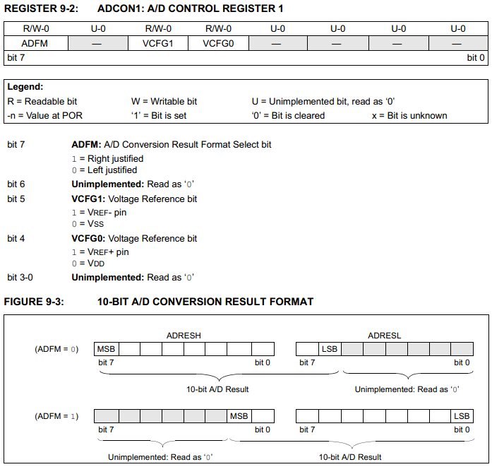
ADFM - There are two registers in which the 10-bit ADC result is stored, these are "ADRESL" and "ADRESH". This bit allows the data to be left or right justified, this may be down to personal preference but I would normally choose the data to be right justified, bit set to logic 1.
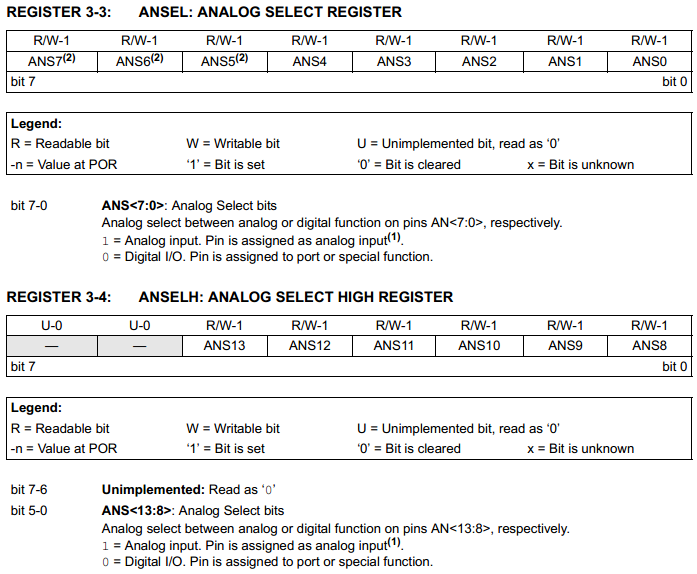
Secondly we need to configure our input pins as analogue and not digital as we originally did at the start of the program in the initialisation.
Quite simply instead of clearing the port, I would set the bits to logic 1 of the pins that I would like to use as ADC.
The port should also be set as an input using the "TRIS" file register, "TRISE" for my program. However if the port is left it will still work as an analogue input, care must be taken to not turn the outputs on.
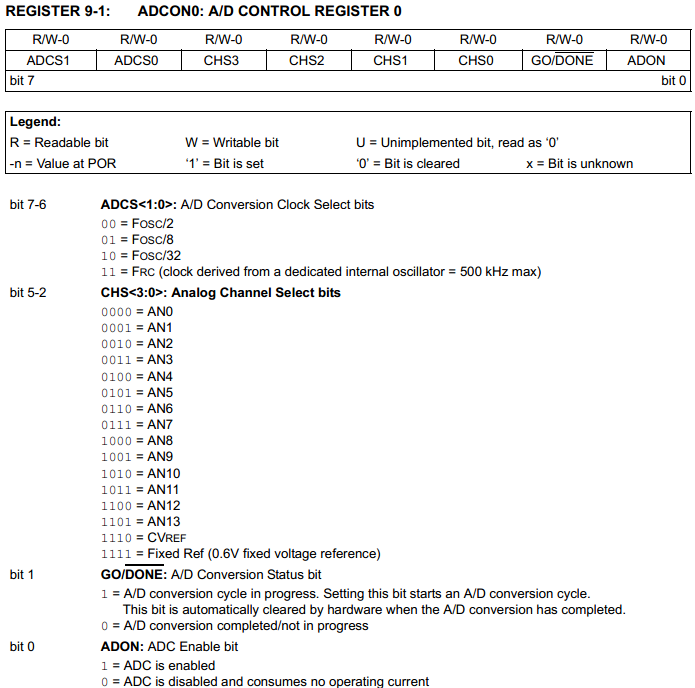
There is another setting for the ADC which chooses which pin to measure, the speed at which it does so and two control bits to enable and start the read process.
ADON - This turns the whole ADC unit on or off, this bit wants to be set to logic 1.
GO/DONE - When this bit is set to logic 1 it initiates the conversion of analogue to digital. When this bit returns to 0 it means that the conversion has been completed.
CHS - The channel select does as it says, you can only measure one ADC input at a time.
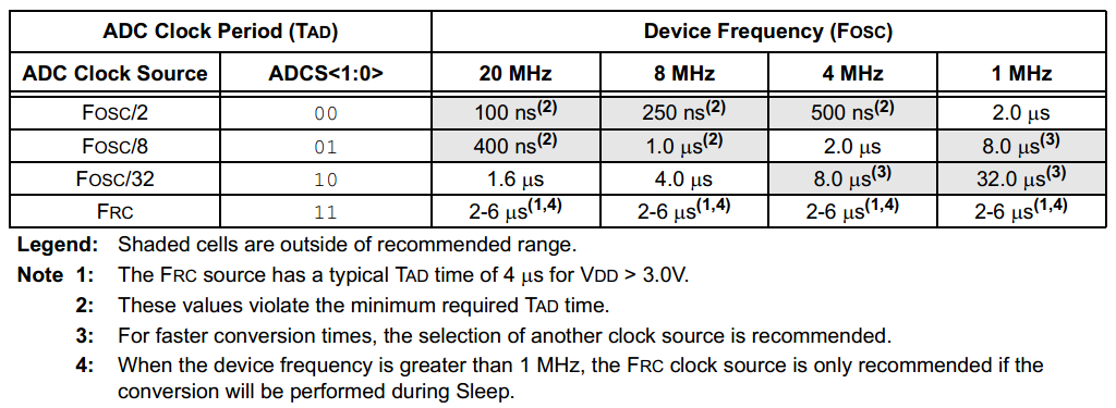
ADCS - This is the speed at which the conversion happens, the faster the conversion the less accurate the measurement will be. It also takes a total of 11 of these conversion clocks to read a byte.
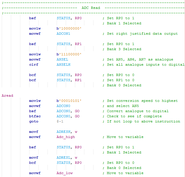
The following program is fairly simple, the first section sets AN5, AN6 and AN7 to analogue inputs. It then sets the data output to be right justified. This section of code should be placed in the initialisation section at the start of the program.
The second section selects the port bit to be measured along with the conversion speed.
The "GO" bit on the "ADCON0" register is set to logic 1 which sets the analogue to digital conversion process going.
The "GO" bit is checked, if it is still logic 1 then the conversion has not yet completed and will loop around to check again.
Once the conversion has been completed both of the registers need to be put into two variables.
The program returns from where it was called.
Something to be noted is the fact that there is a maximum operating speed for the analogue to digital conversion which can greatly slow down a program. Due to me running the microcontroller at 20MHz it means that I must set the "ADCS" bits as "10" in order for conversion to be accurate. A higher speed can be set but may result in false readings, the only way to speed up the process is by using an external converter.
That step is now complete so it is time to put the program together, from now on I'm not going to bother with circuit diagrams or a digital representation of the breadboard, the port definitions are in the program which explain where everything goes. I was going to create a program that would read three analogue inputs every minute, the difficulty is taking a measurement every minute and how accurate we want that time scale to be. While waiting between each reading the program also needs to be scanning the keypad input so it knows when to stop. There are three ways of doing this, one is by simply looping the program "x" number of times, this could be accurately done by toggling an output and using an oscilloscope to get that timing down to a minute. One is to use an accurate external timer, the program scans an input every cycle and takes a measurement when this input flags. The other option is to use something called a timer which can be used with or without an interrupt, as mentioned later.
So which is the best method, well all of them work to some degree but two do have their flaws. Looping the program several times can be quite an accurate method and is used quite often although very difficult to get it accurate, hence using an oscilloscope to help with timing. Using an external timer just adds an additional circuit and reduces the available pins, yes it would be easier and probably more accurate but it simply isn't done. Using a timer along with an interrupt is by far the best method and certainly the most accurate, this will be utilised in the next chapter. For now I'm just going to take one set of readings and place them into the EEPROM.
The program will work similar to that in the last, a password is entered to unlock the system, instead when the star key is pressed it will bring up another menu allowing the user to make a measurement, read the measurement, return to the previous menu or lock the system. Firstly I will discuss the part that reads the analogue.
Another problem that can occur with reading multiple analogue inputs is that if correct delays are not implemented it can cause false readings. The section of the chip that reads the analogue contains a capacitor, when the conversion is made the capacitor is disconnected and then the voltage across it is converted to digital. When we select the different analogue pins we are diverting the input to this capacitor, as we know capacitors need time to charge. There is a calculation to this time but a general rule is that 10us is sufficient for the capacitor to charge, this delay must be before the analogue is read.
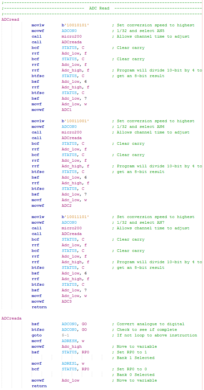
There are a total of three reads of the ADC as each pin must be dealt with separately.
The first pin is selected and set to the fastest conversion speed possible, (1/32 in my case).
A small pause is used to allow the capacitor inside of the conversion unit to settle to it's new value.
The read program is called up which moves the data into two variables, a high and a low.
When returned from the program the low variable is first shifted to the right two places which is the same as dividing the number by four, the bytes in the high variable are also shifted twice and placed in the most significant end of the low variable. The low variable is then placed in new variable, "ADC1".
Since we are only wanting the value in the lower variable we must ensure the carry is first cleared as we don't want to load the high bit from carry when the register is shifted.
The purpose of dividing by four is just to reduce the number into an 8-bit format which is a lot easier to deal with than using two variables.
Since there are three pins to read the process is repeated three times with three different variables for the results.
This section is the same as the example provided earlier, all it does is initiate the read process and place the values from the registers into two variables, a high and a low.
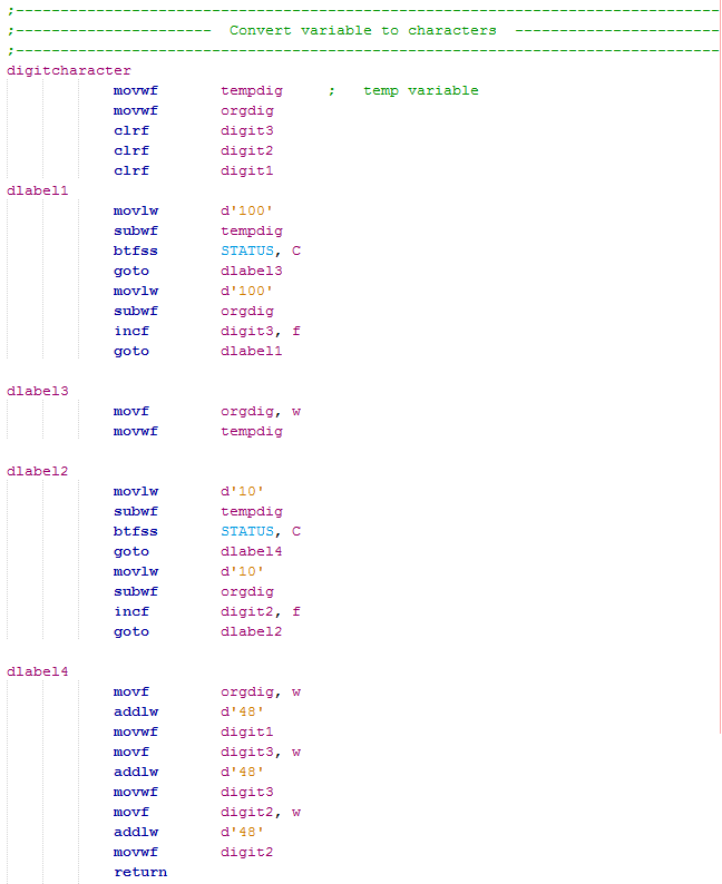
Another program I really need to talk about is one that will convert a decimal number into three separate numbers to display on the LCD. For example if I was to read the analogue value and end up with something like "123" then sending this to the LCD would output the character "{" which is not what we want.
So how is this split up into three digits, one way is to count the number of hundreds, tens and ones splitting these into three separate variables to be sent to the LCD.
So firstly a number is already placed in the working register, it is then placed into two variables, this is very important.
To count the number of hundreds in the variable you must take away 100 from that variable, using the "subwf" command will subtract the working file from a variable which is an odd way round. After the subtract the status register will flag if the sum has been converted successfully, if it goes into a minus the carry bit will go zero indicating a borrow has occurred, again a little confusing.
Since there is 100 in the variable to take it will skip and then minus 100 from the second variable along with incrementing a digit variable (hundreds digit), when it loops around again the flag will be zero and branch off to "dlabel3", the first variable is in the minus and no good, the second variable is still intact and replaces the first variable.
The process will repeat again until all of the tens have gone, what is left afterwards are the ones which can go straight into the first digit variable.
The digit variables then have 48 added to them which converts them to ASCII ready for the LCD. This process can be scaled up to deal with bigger numbers as shown in a future project, the chronograph.
Now it's time to deal with the main program, again here are the links to both the - Program Picture or the - Program Text.
There are a couple of extra points to note in the program. For one some of the messages have been sent as long strings instead of using a lookup table, these use very little extra memory and use a lot less instruction cycles, it's a lot easier to insert variables in these strings than it would if I were to use a lookup table. Another thing to note is the message that says that the analogue reading has been completed, there is a one second delay stuck in there, otherwise the message would flash very fast as the analogue conversion has been set to the fastest speed.
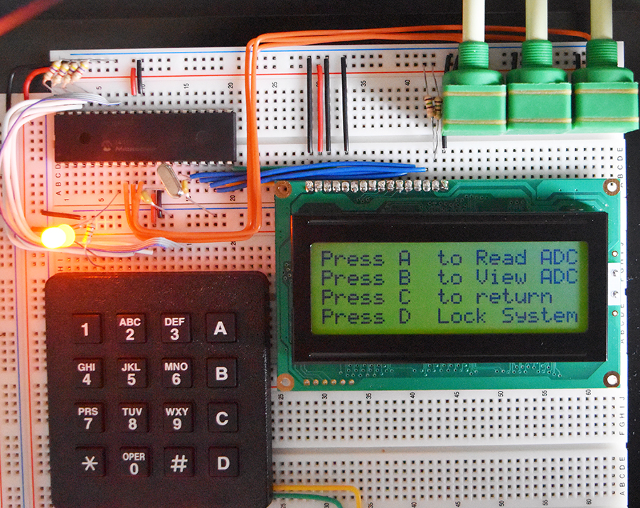
Below is my update circuit on breadboard, note the addition of the potentiometers to mimic a sensor input.
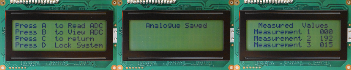
Here are the three new display messages on the LCD.
As you can see it is pretty easy to deal with reading analogue and it can be pretty fast too, but what about several readings. The next program will make a series of readings every second, a total of twenty readings and 60 results. The next chapter will concentrate on the interrupt and the timer which are both very important when accurate timing is needed, again the project will be a datalogger.
Hello, if you have enjoyed reading this project, have taken an interest in another or want me to progress one further then please consider donating or even sponsoring a small amount every month, for more information on why you may like to help me out then follow the sponsor link to the left. Otherwise you can donate any amount with the link below, thank you!