Microcontrollers 11 - Interrupts and Timers
This is only going to be a small section on interrupts as I tend not to use them much. The project will be a datalogger that will record twenty measurements from three analogue ports every second and save them in EEPROM to later be viewed on an LCD. So an interrupt can be internal or external, when an interrupt is to occur it will leave whatever it was doing and branch off elsewhere, the interrupt can be returned to where it left off similar to that of the call function. The issue with interrupts is that they can leave the program at any time, the problem is that the working register will likely be changed in the interrupts program. There are a few things that can be done, such as the working register to be saved in a variable when it enters the interrupt program and then placed back in at the end of a program or interrupts could be disabled when the working register cannot be tampered with, such as when writing EEPROM.
So why use an interrupt? well say for example your program goes into a delay subroutine and an external event occurs, scanning the input inside of the delay is not an option as the delay is universal in the program, it simply cannot have inputs placed into it. The other option would be to wait for the delay to be completed, this may be ok for a mechanical switch input but it does not allow for any precise timing. The other option is to set up an interrupt condition, when this condition is met it will immediately jump to the interrupt program and finally return to where it left when the interrupt program passage has been completed. Remember the program should start at 05, when an interrupt occurs the program will jump to address 04. When writing a program it is normal to have a goto instruction at the start to skip after the interrupt as you will see further on.
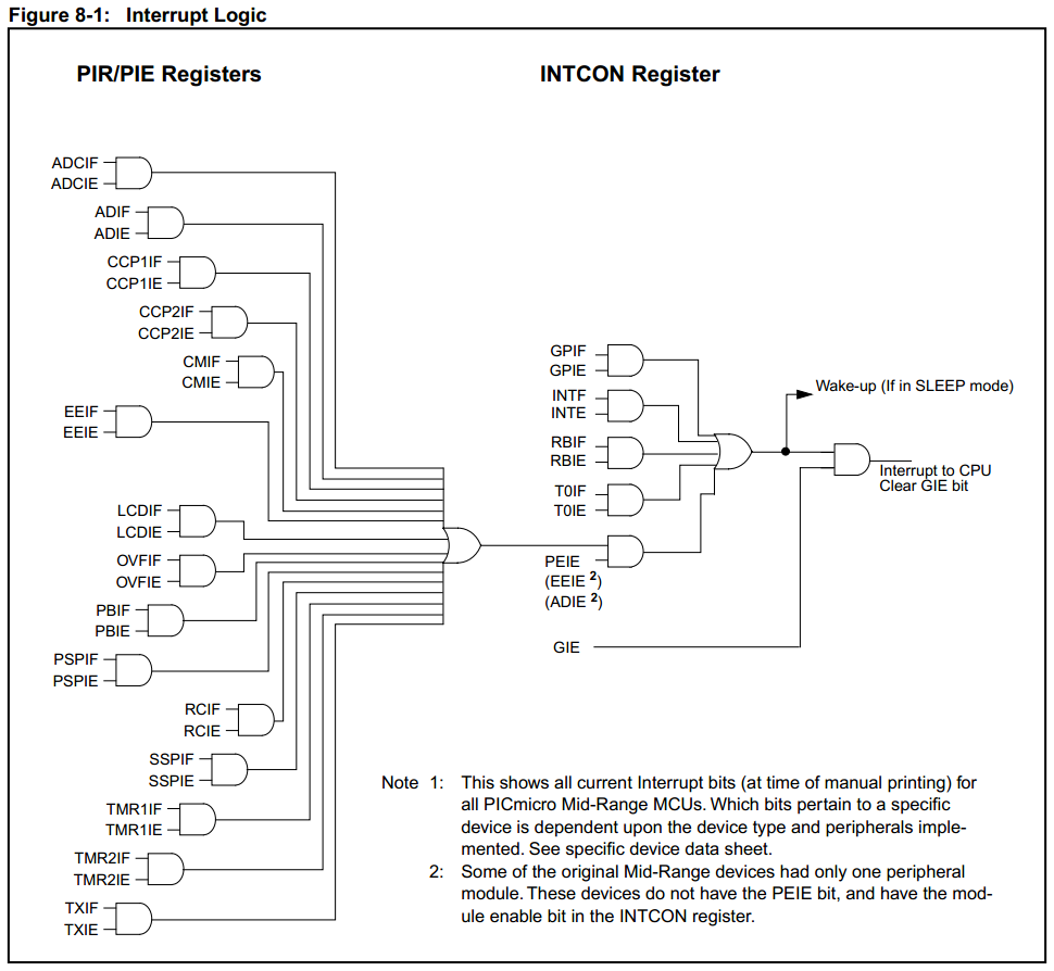
There are so many scenarios that can lead to an interrupt as shown in the below diagram. You'll notice that all of the individual interrupts have two inputs, one is the enable input and the other is the flag input. All of the required information can be found in the microcontroller's pdf of what registers to set, the best information source of how to understand interrupts is the following - Interrupts Guide
The first register to talk about is the "INTCON" register as this is where the interrupt function can be enabled / disabled.
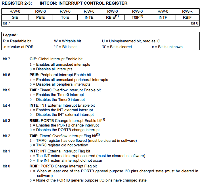
GIE - Global Interrupt Enable bit - This enables the whole of the interrupt function, soon as the interrupt is called this bit is automatically cleared to stop other interrupts from initiating, when returned this bit will enable again.
PEIE - Peripheral Interrupt Enable bit - This is to enable the majority of the interrupts as explained later.
T0IE - Timer0 Overflow Interrupt Enable bit - Exactly what it says.
INTE - External Interrupt Enable bit - There is only one external input pin that is used to initiate an interrupt.
RBIE - PortB Change Interrupt Enable bit - This is to enable an interrupt condition to occur if the state of PortB inputs RB4 - RB7 change.
T0IF - Timer0 Overflow Interrupt Flag bit - This bit will flag when Timer 0 overflows, it will only initiate an interrupt condition if T0IE is enabled.
INTF - External Interrupt Flag bit - When the external interrupt changes states, normally RB0, it will initiate the interrupt condition if INTE is enabled.
RBIF - PortB Change Interrupt Enable bit - If the inputs RB4 - RB7 change their input states then this flag will initiate the interrupt condition if RBIE is enabled.
As you can see it's fairly easy to see what's going on, one bit is to enable an interrupt and the other is to flag when an interrupt condition has been met. Like Timer0, Internal interrupt and PortB interrupt there are many more in the peripheral registers. There are four more registers, the PIE1, PIR1, PIE2 and PIR2. The PIE registers are to enable the interrupt and the PIR registers are to flag when a condition has been met.
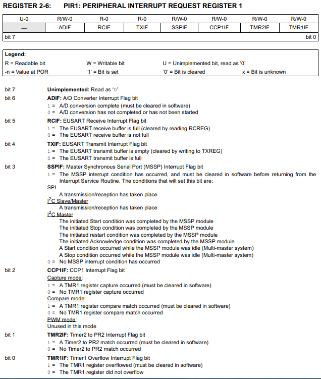
I have chosen to include the flag register and not the enable registers as the layouts of the bits are the same, the flag register also explains how an interrupt condition is met.
ADIF - A/D Converter Interrupt Flag bit - As you know in that last chapter the analogue conversion can take quite a number of clock cycles to complete itself, infact reading analogue is very slow for an accurate measurement. Instead of waiting for the conversion to complete the program can continue to do whatever it wants, when the conversion has been completed this bit will flag, the program could interrupt and deal with the captured information.
RCIF - EUSART Receive Interrupt Flag bit - I will go into more detail in the next chapter on what this is about but this is the single most important use of the interrupt, when serial data has been received the chip can deal with the information straight away so that it is ready to receive more data.
TXIF - EUSART Transmit Interrupt Flag bit - This will interrupt when serial data has been sent, this is for when the program needs to be doing two things at once, so serial data is sent, the program returns to do something else, the interrupt flags when the data has been sent so it can send some more.
The rest of these bit's will be explained later in this chapter, or in another.
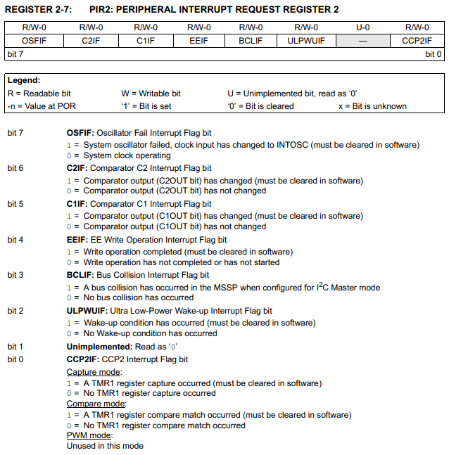
The rest of these interrupts are rarely used as comparators are generally used outside of the chip, an oscillator failure is extremely unlikely, the rest will be explained at a later date.
EEIF - EEPROM Write Operation Interrupt Flag bit - like the ADC the EEPROM can take a little time to complete writing, so when the two special numbers have been sent to the EECON2 register and the write sequence has started the program can return to whatever it was doing. Once the write procedure has been completed the interrupt flag will indicate it has done so, this is quite valuable as the write will take around 5ms.
I really don't have to explain any further about what an interrupt is, to be honest they are sometimes more trouble than they are worth and a program has to be carefully designed so that when a condition is met it doesn't cause any bugs in the program. There really only are three instances that I will use an interrupt, one is for an external input which needs accurate timing, the second is serial and the other is something called a timer. In this particular chip there are three timers, here is a quick summary of them all from the datasheet;
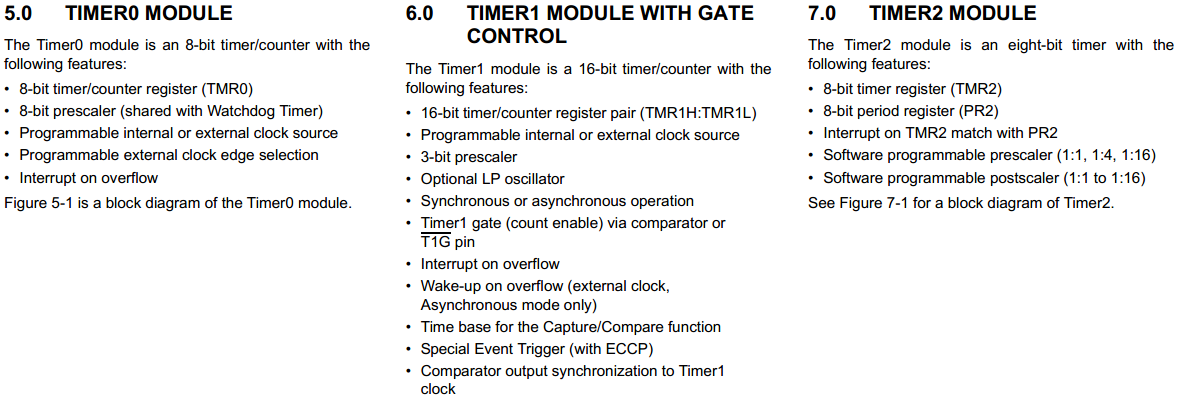
So what does a timer do, well it basically just counts / increments a register. The first timer is mainly associated with the watchdog timer, when the 8-bit timing register overflows it with either flag the watch-dog timer or an interrupt depending how the timer is configured. There is a prescaler which scales down the clock cycles to timer increments, for "timer0" this is a prescaler of between 2 to 256 clock cycles per register increment, however the watchdog has two prescalers, one is 1 to 128 and the other is 32 to 65536. Generally "timer0" is kept for the watchdog timer which when set will reset the chip every time it overflows unless cleared periodically.
"Timer1" is a little more special as it has two addresses which hold a value of up to 65536 and a prescaler of either 1, 2, 4 or 8. What makes the timer really special is that it allows for an external clock source, so for example if a very accurate time scale needs to be acquired and will not divide down to fit then the appropriate external crystal can be used. With this timer it is solely used for an interrupt which is triggered when the registers overflow. Now since the crystal will be 20MHz that will mean a clock of 5MHz and a period of 200ns which means that a very precise time measurement can be acquired. For example say I want to time 10ms, using the largest prescaler will take this up to 1600ns, it would take a further 6250 counts to make 10ms. Loading the two registers with 59286 would be the start of the timer, after 6250 increments the register would overflow causing an interrupt, the program can then be dealt with accordingly.
"Timer2" is a little different, this has two registers, one that increments and the other is a comparison. There is a prescaler (1, 4 or 16) and a post-scaler (1 to 16). The prescaler will divide down the clock and then increment the timers register, before the timer is started the comparison register is loaded with a number. When the timers register increments enough to match the comparison register it will reset the timing register and increment the post-scaler, when the post-scaler reaches the correct number it will flag the "timer2" interrupt.
So which one is the best for timing, well it all depends of the duration of the time and the accuracy needed. All of the timers do infact deal with a very short period of time when using the 5MHz clock frequency, infact when you take into consideration the size of their registers with respect to the prescalers and post-scalers they come out very similar, both the "timer0" and "timer2" come out to have a maximum of 65536 clocks whereas "timer1" comes out with a maximum of 524288 clocks. So which one would you choose, "timer0" is generally kept for the watchdog timer as "timer2" can be scaled more accurately. "Timer1" is the most special one as it allows for an external source, so really it doesn't matter what frequency I run the main microcontrollers program at.
Something else to take into consideration is that even though these timers are not quite capable of the 1 second timer that I require at my clock frequency it really doesn't matter as I can increment additional registers. I always choose "timer1" due to the size of it's register, now if I use the largest prescaler and increment 62500 times I will get a delay of 100ms, each time this interrupts I can increment another register, after 10 increments it will equal one second and then a measurement can be taken, the whole process will start again.
Here is "timer1" and the block diagram of how it works.
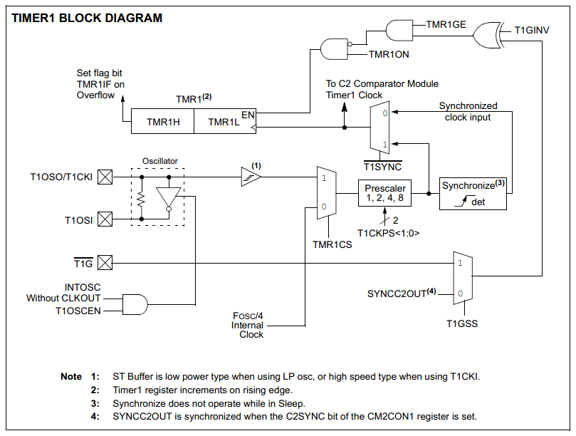
There are quite a few extra's to point out here as one of them is used in a chronograph project.
Firstly there are three external input pins, two of those are for the clock source if required and connect to RC0 and RC1. The other pin is to enable the timer to start or stop, T1G which is pin RB5. In this instance the program sets the registers to zero and sees what's in them after the timing period, if the period elapses then the interrupt flag is set to notify this condition.
Note also that there are three oscillator sources, an extra external one, the main one clocking the microcontroller (also external in my case) and an internal 32kHz one.
Another thing to note that the external oscillator should be no more than 5MHz as this is the maximum speed the chip can clock at, running any faster may damage the chip.
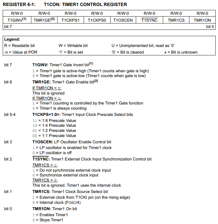
There is one main control register for this timer and once initialised there is only one bit that needs to be used.
T1GINV - Timer1 Gate Invert bit - When using an external pin to start the timer counter going this will allow the pin to be inverted, so either active-high or active-low can be chosen.
TMR1GE - Timer1 Gate Enable bit - This is to allow the capability of using the external input pin to start the timer counting, the bit to enable the counter still needs to be set too.
T1CKPS - Timer1 Input Clock Prescale Select bits - This is to choose how many times to divide the clock source.
T1OSCEN - LP Oscillator Enable Control bit - This is to enable the internal RC oscillator which is 32.768kHz
T1SYNC - Timer1 External Clock Input Sync Control bit - The external clock can be synchronised with the internal clock, it is wise to not synchronise when using an external source, set the bit to one.
TMR1CS - Timer1 Clock Source Select bit - This is to choose between the internal clock or the external, since I will be running the maximum 20MHz then there is no need to use an additional clock other than if I wanted a specific frequency.
TMR1ON - Timer1 On bit - This is the enable bit of the counter, it will keep counting until set to zero.
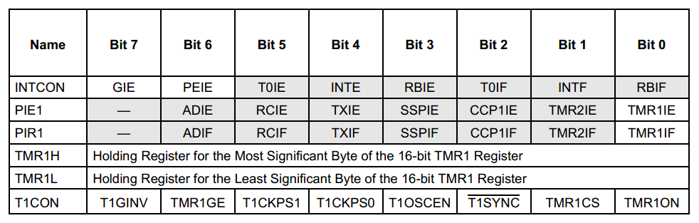
There are a total of six registers to worry about. Firstly the "INTCON", "PIE1" and "PIR" registers are to set up the interrupt, the first two of these registers will enable global interrupts "GIE", peripheral interrupts "PEIE" and then the "TMR1E" bit. Once set these can be left, when the interrupt condition is met it will jump to location 004 in the program where the "TMR1IF" bit will be cleared in the "PIR" register. Otherwise the remaining three registers are directly involved with the timer. The "TMR1H" and "TMR1L" registers are used to set the number of increments until an over flow, this is simply the number 65536 minus the number of increments needed. The last register "T1CON" can be placed in the initialisation process at the beginning of the program to setup the prescaler, clock source, etc... The only bit of the register that will need to be addressed again is the "TMR1ON" bit which sets the timer going.
My program will now take a series of twenty measurements of analogue with one second spacing's between each, each reading consists of three results, one from each analogue pin. The result of the analogue is saved in an EEPROM address. Every 100ms the program will interrupt, set the timer going again and increment a temporary register, when this register reaches ten it will take another measurement. While waiting the program will loop on itself waiting for each interrupt, each one second reading and for the program to complete itself. The program cannot be stopped in this nineteen second time period as I don't want to introduce any bugs to the program and neither do I want to spend unnecessary time adding to a program just for demonstration.
Between each interrupt the program must clear the interrupt bit, stop the timer, load the registers again and then start the timer. This means that every second a total of 12us per second will be wasted, I could remove this error by adding six to the timer registers although this may add confusion to whoever reads the program, plus this time is negligible. The program has an extra menu that allows the user to scroll through the results.
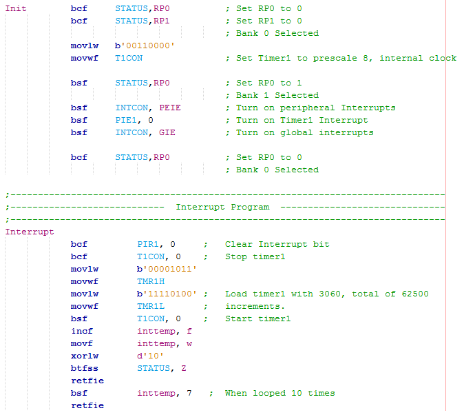
Firstly the interrupt program itself.
In the initialisation stage at the start of the program the timer control register has to be configured to prescale to 8.
Next bank 1 is selected to turn on the peripheral interrupts, then to enable the timer and then to finally enable the interrupt function.
In my program it will set the timer to start counting, when it reaches the end of the register an interrupt will flag causing it to jump to location 004 in the program, at this location is a "goto" command redirecting it to this section of code.
The interrupt bit is cleared, the timer stopped and then a value loaded into the two registers which will result in total of 62500 increments which is equal to 100ms.
The timer is started again, a temporary variable incremented and the interrupt is returned. The interrupt will call up another 10 times, when it does so it will branch to set a bit on a variable. When returned this bit will indicate a second has passed causing it to take another analogue measurement, the variable is cleared in the process.
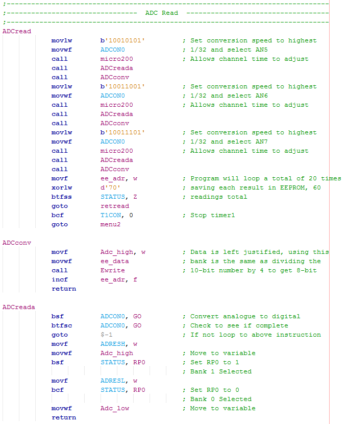
When the analogue is set to be read it follows a similar process to the project in the previous chapter.
The specific analogue channel is set along with it's conversion speed, a delay program is called to allow the internal capacitor to settle.
Another program is called which reads the analogue splitting it into a high and a low register.
A third program is to be called which sends the high data from the ADC variable to EEPROM, I chose to left justify the analogue results so I didn't have to rotate the registers.
After this program has been called twenty times it will stop the interrupt timer and return to the previous menu.
After the data has been written to the EEPROM, the data address is then incremented ready for the next result. The program will do a total of 20 reads causing it to increment from address 10 to address 70, in the section above it will detect this 70 stopping the interrupt timer and return the program.
The program will still allow the user to set a password, unlock and lock the system. There is still a second menu allowing the user to read the analogue, view the results or otherwise. The difference is that when the analogue is set to read it will save the value at zero seconds and then every second thereafter up to nineteen seconds, a total of twenty sets of 3 results, 60 total. When the user wants to view the values it will bring up a second menu telling the user what key to press to scroll up or down through the readings and the buttons to return.
Here are the links to both the - Program Picture or the - Program Text.
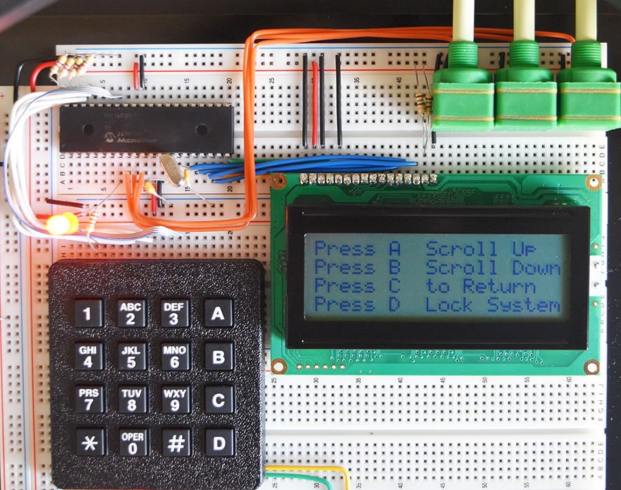
Here is the circuit on the breadboard, it is exactly the same as in the last chapter, note the third menu on the display.
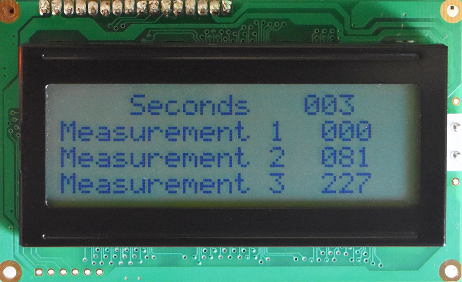
Here is an example of scrolling down to the third second to see it's result. Since this EEPROM is shared with the password if you scroll up too far you can view it, there is no point in blocking this feature for this demonstration.
Now you should have an understanding of how to read multiple analogue inputs and how they are to be saved to EEPROM. You should also be able to initialise an interrupt and know why one may be necessary. The next project will introduce serial communication as this is vital for most accessories or modules to interact with a microcontroller, such as the GPS module I use in a later project.
Hello, if you have enjoyed reading this project, have taken an interest in another or want me to progress one further then please consider donating or even sponsoring a small amount every month, for more information on why you may like to help me out then follow the sponsor link to the left. Otherwise you can donate any amount with the link below, thank you!