Microcontrollers 12 - Serial - EUSART
For this project I will locate the analogue reading to a separate chip, this chip will be known as the slave. The slave chip will receive some information from the master chip telling it the time interval for the measurements and also the number of measurements to be taken. The slave chip will take these series of measurements which will be sent to the master chip to be saved into the EEPROM. The information will be sent via serial communication. This project will utilise the currently existing setup with the keypad and LCD on the 16F887, this will be the master chip. The slave chip will be another 16F887 as the 16F628A does not support analogue, there will be a total of eight pins to be measured and a maximum of 240 singular measurements.
In digital electronics there is either parallel or serial data communication, parallel is a lot faster as there are more data lines whereas serial would be required to run 10 times faster if it were to run the same 8-bit amount of information. The great thing with serial is that just one data line can be used which saves on space and allows for the other pins on the chip to do something else or allows for a smaller chip. As you will notice in the microcontroller world the majority of the modules out there will be serial, for example the GPS module I use in a later project. Another example is data storage which is covered in the next chapter, using serial to save data on a separate EEPROM chip.
This chapter is valuable as it deals with both reading and sending serial data, it will also explain the use of the interrupt as mentioned in the previous chapter. There are two main different types of serial port to use; EUSART and MSSP. The EUSART (Enhanced Universal Synchronous Asynchronous Receiver Transmitter) deals with the most common type of serial known as asynchronous, SCI or RS232, it can also run as synchronous, it only requires the use of two pins. The MSSP (Master Synchronous Serial Port) can work at a far faster rate but it needs to synchronise with it's master or it's slave, this generally requires between two and three pins. MSSP (SPI) and I2C will be discussed in a future chapter as these are the industry standard methods for serial communication.
I will be using EUSART as it's so easy to deal with and in many applications is fast and accurate enough. Note that EUSART can run in synchronous mode and requires two pins, a clock and the data. Normally when dealing with serial it is almost always going to be asynchronous as nearly all microcontrollers have a stable clock source, some can also auto-detect the speed of serial.
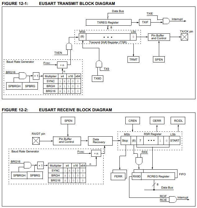
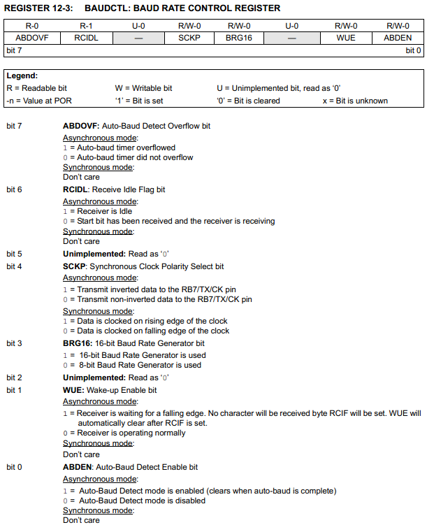
I have included two block diagrams to show how both the transmit and receive functions work, or how everything is linked together. Note that these modules can work independently, so you can send and receive at the same time - only with asynchronous.
It is quite simple to use and only requires a total of three registers for all of the functions plus an additional two to select the baud rate. One register is for the transmit, one for receive and the other to control it's baud. The other two depending if running 8-bit or 16-bit will determine what the baud rate is, if running 8-bit then only one register is used.
What is baud, a baud is a unit of data measurement, it is the number of bits per second. A common baud rate is 9600, so 9600 bits of data per second. Serial works in 10-bit, the first is the start bit, the next eight are the data bits and the last is the stop bit. 9600 baud would translate to 960 bytes of data per second.

The serial port is pulled high when initiated, the start bit is always a low bit and the end bit is always high. To the left is a screenshot of my oscilloscope, there are two bytes being sent.
Since the baud rate is 9600, each bit would have a period of 104us.
As you can see the first bit drops to zero which indicates a start bit, the next eight 104us period bits are the data and then the last 104us positive bit is the end.
The two strings are;
0101010001 and 0001100001
One thing to note with serial is that the low bit is sent first and the high bit last. So swapping the bits and removing the start and stop;
00010101 and 00001100 or 21 and 12 decimal
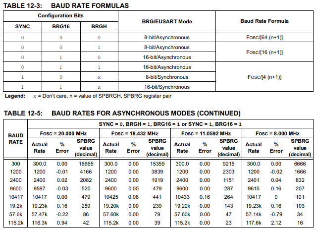
Firstly the baud rate control register has a few options to be set, it is normally done in the initialisation stage of the program as it doesn't really need to be touched again after that.
ABDOVF - Auto Baud Detect Overflow bit - The microcontroller has the ability to automatically detect the baud rate of an incoming signal, this occurs when a partial signal is sent. There is a timer that starts when the start bit is detected, if for some reason there is no stop bit or the serial is too slow then the timer will overflow and this bit will flag.
RCIDL - Receive Idle Flag bit - This bit indicates when serial signal is being received.
SCKP - Synchronous Clock Polarity Select bit - This all depends how the data is being sent, whether it's synchronous or asynchronous. Since I will be using asynchronous it is best to set this bit to 0, this tells it not to invert the serial output signal.
BRG16 - 16-bit Baud Rate Generator bit - This is one of the options to set the baud rate on the chip, I will explain later on in this chapter.
WUE - Wake-up Enable bit - This is for when the chip is in sleep mode, it will awake when serial data is received, it is also attached to the interrupt function on the serial receive, it is best to just leave this as logic 0.
ABDEN - This automatically detects an incoming signal and determines what it's baud rate is, this is if you have no idea what the incoming baud rate is. It is actually very reliable and it is advised to enable this bit especially if the incoming signals clock source can vary, temperature change, etc... My clocks are reliable so I choose not to do so.
Next I will deal the baud rate generator as this requires a total of four registers in order to select a rate. The user also needs to know what speed they want their baud to run at, quite often it is chosen at 9600.
If you look at the baud rate formula you will notice that with the addition of a +1 it doesn't make the clock frequency perfectly divisible. This means that your chosen baud rate may not be exact and will have a degree of error. There are a number of tables in the data sheet that show the baud rates with respect to the oscillator and the degree of error. There should be a maximum error of 5% between devices, it is advised to keep each device with no more than 2% error.
Since I will be running 20MHz at 9600 baud I will look for the settings with the least amount of error, as shown in the table to the left. The error is quite minimal and it tells me what the register needs to be configured as.
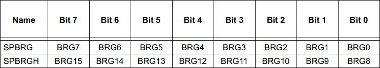
The SPBRG value is 520 so this value needs to be sent to the following registers, these are to set the baud rate value. The bit BRG16 in the baud control register also needs to be set, 16-bit mode on the baud generator.
As stated the SYNC bit needs to be set to zero and BRGH bit set to logic 1. To set these bits they are done in the TXSTA register which is also used to set up the transmit conditions.
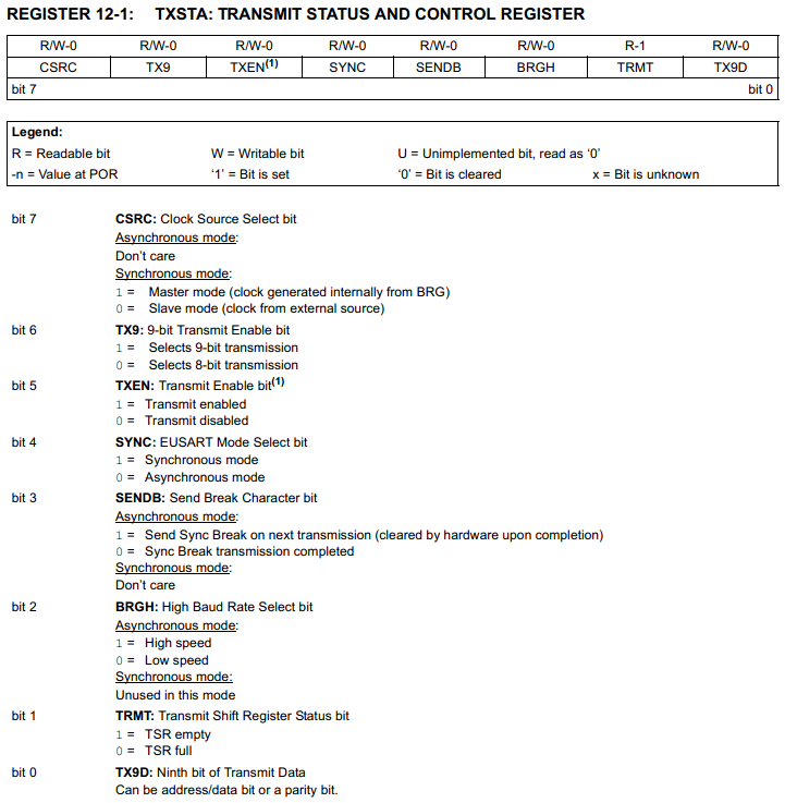 CSRC - Clock Source Select bit - Since I will be dealing with asynchronous it doesn't really matter what I set this bit as. Although if it was synchronous then this would determine weather this chip provides the clock source or another.
TX9 - 9-bit Transmit Enable bit - This allows an additional bit to be sent, this could be a carry bit from the chip it is communicating with. All this does is save time by sending one 9-bit string rather than two 8-bit strings, it is commonly implemented for addressing as explained later.
TXEN - Transmit Enable bit - When this bit is enabled it will allow the serial data to be sent.
SYNC - EUSART Mode Select bit - This will set the serial data to either synchronous or asynchronous mode, I will leave as logic 0.
SENDB - Send Break Character bit - This is just a blank space of information, it has a start bit, a 12-bit data word and an end bit. The break has no data purpose and is only to put a delay into the system, it is normally used in conjunction with sleep mode. It is also used in the data transfer of the RS232 serial data standard.
BRGH - High Baud Rate Select bit - Runs high or low speed, this is to set up the baud rate as mentioned earlier.
TRMT - Transmit Shift Register Status bit - This indicates when the transmission has been completed, this bit can be polled so the program knows when to send more data.
TX9D - Ninth bit of Data Transmit - This is the 9th bit that can be transmitted, normally left zero when unused. It can be used to indicate whether an address or data is being sent.
The registers are a little mixed up as the previous had controls for the baud rate and whether it was running synchronous or asynchronous. Likewise this register is not just for receiving data it is also associated with enabling the serial port on the chip. You will notice that this chip only has the capability for just one EUSART transmission and one capability for MSSP transmission. It is quite possible to write a simple program to transmit serial data, it is a little harder to write a program to receive data, this is known as bit-banging, the chip is not all that limited in capability.
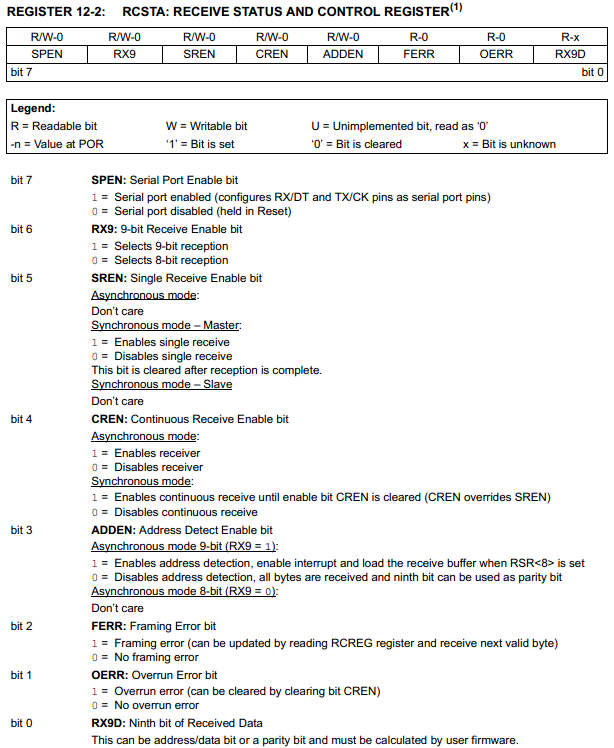
SPEN - Serial Port Enable bit - This is to enable the pins 25 and 26 to be used as the serial communication pins, receive and transmit in asynchronous or data and clock for synchronous.
RX9 - 9-bit Receive Enable bit - This is to allow the chip to receive 9-bit data, it is rarely used so best to leave logic zero, it can be used to indicate whether an address or data is being received.
SREN - Single Receive Enable bit - This is only for synchronous mode, when this is set it will clock the clock output until all data has completed being received through the data pin, so once complete the clock will stop and SREN bit will clear.
CREN - Continuous Receive Enable bit - This will enable the receiver in asynchronous mode and will clear itself when the data has been received. In synchronous mode it will keep the clock pin going until the bit has been cleared, this is not automatic. Using CREN in synchronous mode will automatically put SREN to logic zero.
ADDEN - Address Detect Enable bit - This is one useful purpose for receiving data in 9-bit mode, so if the RX9 bit is set it will tell chip an address location is being received, if zero it will just be data. This is very useful as it can tell the chip where it wants to write data and the second transmission what data. Personally I wouldn't do it this way and it's pretty uncommon to do so.
FERR - Framing Error bit - This is when the data has not been read correctly, bits appear to be missing or there are too many, it is normally caused by baud error.
OERR - Overrun Error bit - Too much data has been received either because it's being sent too fast or the received information has not been read in time.
RX9D - Ninth bit of Received Data - Exactly what it says.
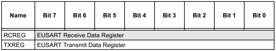
Finally there are two more registers in which the information is to be stored, one for transmit and the other for receive. If the transmit function has been enabled when data is loaded into the "TXREG" it will be sent immediately.
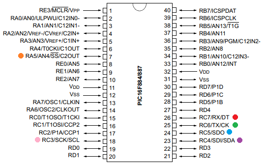
Below is a diagram showing the connections associated with serial, the red and green are solely for the EUSART port whereas the others are associated with the MSSP. Since I will be choosing to use asynchronous it means that the red pin will be used to receive data whereas the green pin is used to transmit data.
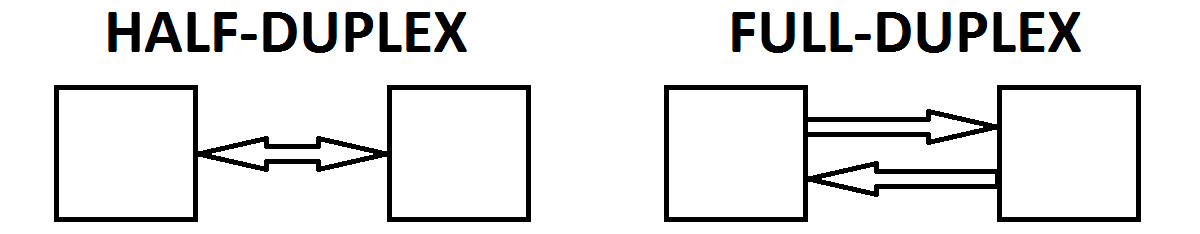
The last thing to discuss is full-duplex and half-duplex. Full-duplex allows data to be sent and received simultaneously, one data line is for receiving and the other is just for transmitting. Half-duplex uses one data line which is bi-directional, data can only be sent in one direction at a time. For the EUSART module the half-duplex is synchronous as one pin is for data and the other for the clock. The Full-duplex module is used for asynchronous as there are only two pins.
There is quite a lot to take in with serial but it is the universally used method for data transfer and makes use of the space on a microcontroller, it is possible to have 128 different modules on a single serial bus as explained later, not normally used with this type of serial but one called I2C.
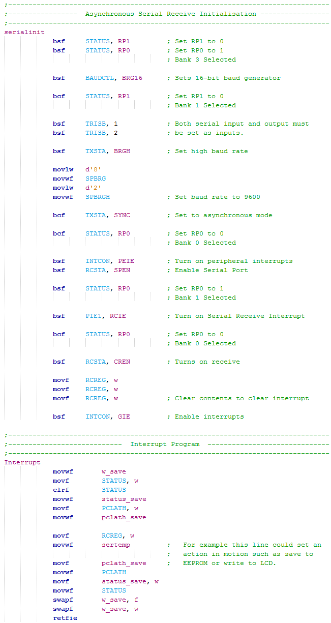
Firstly there is quite a chunk of initialisation process in order to set up asynchronous mode and the baud rate.
The first to select is the "BAUDCTL" which we use to set 16-bit mode. It is one of few registers in Bank 3. This register is not always present in all microcontrollers such as the 16F628A.
Both of the pins used for sending or receiving serial data must both be configured as inputs.
The baud rate is set high and then the two registers are loaded to set the rate, again some micrcontrollers only have one register.
Asynchronous mode is selected.
The interrupt is setup but not turned on yet along with enabling the serial port.
The receive function is enabled, the port is now ready to receive data.
The data register is read a total of three times which clears the interrupt flag register, the global interrupt is then enabled.
When data is received it will call an interrupt, the first step is to save the contents of the working register, the status and also the PCLATH just incase a page has been crossed.
The data is dealt with which is normally placing it in another location or doing something with it, this allows more data to be received. Note that there is something called the "FIFO" which is two levels deep, it allows up to three amounts of data to be received, two in the FIFO and one in the receive register.
The Interrupt routine is finished by replacing the PCLATH, the status and the working register.
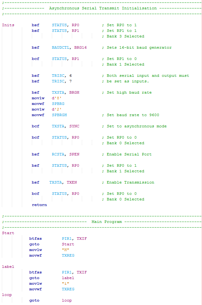
The serial transmit has a similar process.
The initialisation stage is exactly the same except there are no interrupts, they can be a little troublesome.
The difference is that the "TXEN" bit is enabled which allows serial to be sent.
The transmit interrupt is always flagged unless it's send registers are full. So enabling an interrupt is quite a pain in the butt as it flags soon as the interrupts are enabled.
The bit of the interrupt is checked instead, it will be flagged causing it to jump, the letter "H" is loaded to the working register and then loaded into "TXREG". Soon as the register is loaded it will send the data.
Since the transmit also has a 2-level FIFO it means that it is immediately ready to send more data. For example if you were to send three lots of data the interrupt flag would cease and not allow a branch until the data has been sent and there is room in the FIFO.
The problem with the last section of the above code is that I've found it can sometimes miss bits, the interrupt flag sets before the data has been sent, this however should not happen in theory.
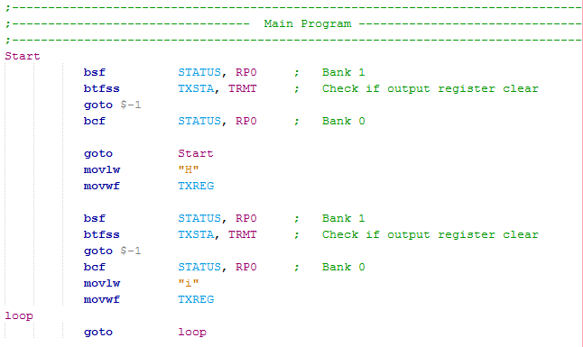
To the left is an all-round better solution as there is a bit in the "TXSTA" register that says whether the output register is clear or full.
If it's full it will simply loop back to check again, once clear it will then allow the program to jump forward and send another byte of data.
It is best to check this byte before sending as if it was after it would only unnecessarily delay the program by waiting for the send to complete itself.
My project will contain both the send and receive functions on both of the chips, since I will be running full-duplex it means I can set both send and receive as they work independently. The master chip will send a serial message telling it how many readings and the time interval between those readings, the slave chip will then transmit the required data back which is saved to the EEPROM. Neither of the programs use the serial interrupts as they are unnecessary, only the timer interrupt is used.
Receive - Program Picture or the - Program Text.
Transmit - Program Picture or the - Program Text.
Here is the new circuit on breadboard, eight potentiometers, one for each analogue channel.
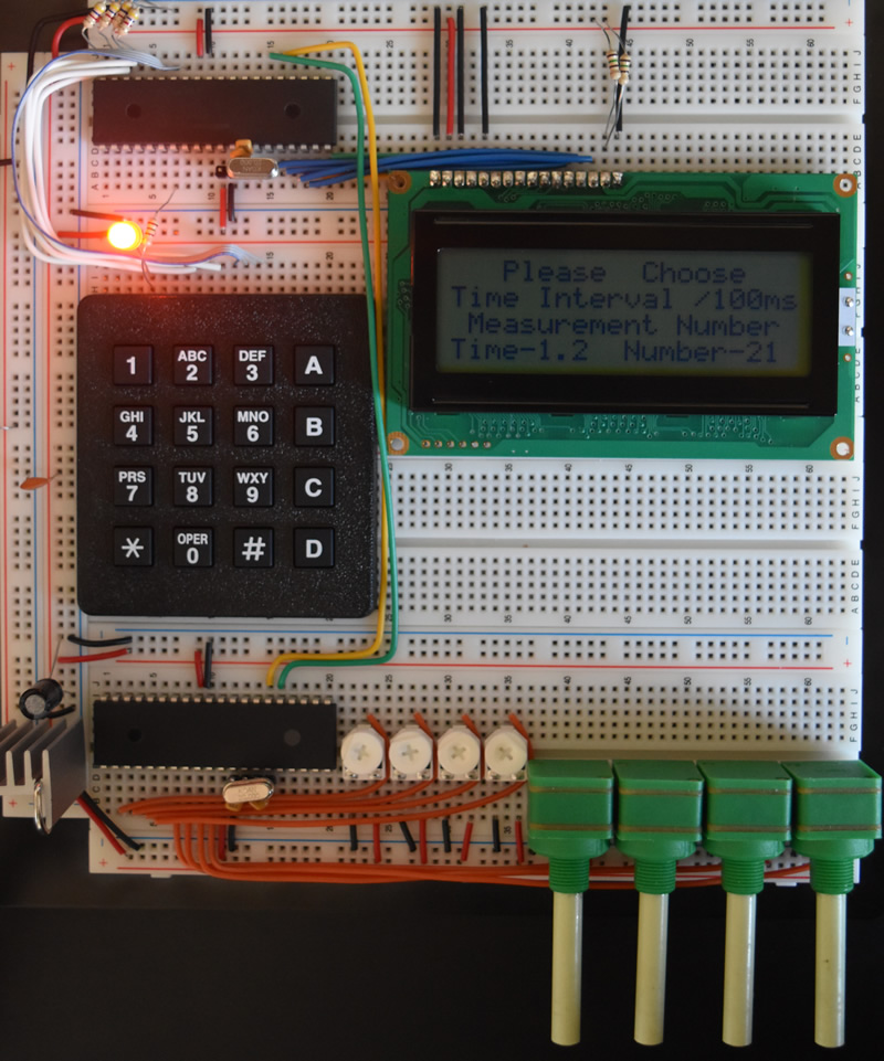
Remember back to the oscilloscope reading of the serial, one number was 12 and the other 21, they were from this example of program.
I have included a couple of smart features in the program. The time and number of measurements are multiplied together to ensure the time interval counter does not overflow. The number eight and the number of measurements are multiplied together to ensure the data acquired does not exceed the capacity of the EEPROM. The time interval will only increment up and down of the measured values.
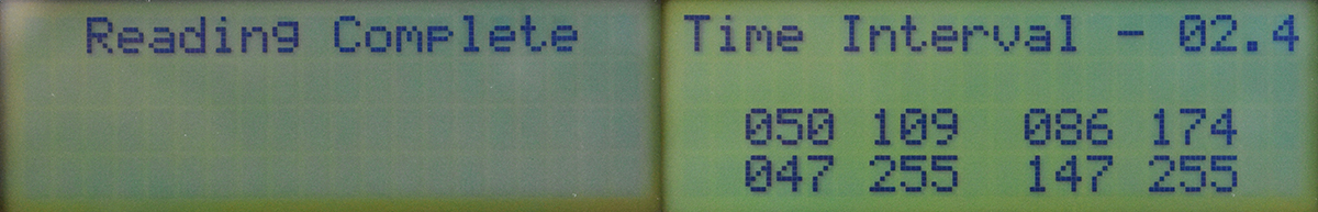
Each byte is around 1ms, therefore when the slave chip sends the eight bytes of data to the master chip the string should be around 8ms long, as you can see this is the case.

Ok so ESUART is pretty useful and has it's places, however there is still the synchronous side of it, SPI and I2C. The next chapter will show how to multiplex an LED display that is controlled by asynchronous serial.
Hello, if you have enjoyed reading this project, have taken an interest in another or want me to progress one further then please consider donating or even sponsoring a small amount every month, for more information on why you may like to help me out then follow the sponsor link to the left. Otherwise you can donate any amount with the link below, thank you!